Transcription
AN2719Application notePrecision improvement techniquesfor the A/D converter of the STM8 microcontrollerIntroductionThis application note describes a selection of hardware and software methods for improvingthe precision of the on-chip A/D converter of the STM8 microcontroller (STM8 ADC). It isdivided into three sections: The first section explains the internal design principle of the STM8 ADC. The next section lists the main types of error that occur in A/D converters and theirsources. The last section describes some hardware and software methods for minimizing theseerrors.Firmware examples (source codes) are provided with this application note showing how toimplement STM8 ADC routines for minimizing measurement errors.October 2008Rev 21/22www.st.com
ContentAN2719Content123STM8 ADC internal hardware . . . . . . . . . . . . . . . . . . . . . . . . . . . . . . . . . . 41.1SAR principle . . . . . . . . . . . . . . . . . . . . . . . . . . . . . . . . . . . . . . . . . . . . . . . 41.2ADC clock . . . . . . . . . . . . . . . . . . . . . . . . . . . . . . . . . . . . . . . . . . . . . . . . . . 71.3Reference voltage . . . . . . . . . . . . . . . . . . . . . . . . . . . . . . . . . . . . . . . . . . . 71.4Multiplexer . . . . . . . . . . . . . . . . . . . . . . . . . . . . . . . . . . . . . . . . . . . . . . . . . 7ADC errors . . . . . . . . . . . . . . . . . . . . . . . . . . . . . . . . . . . . . . . . . . . . . . . . . 82.1Introduction . . . . . . . . . . . . . . . . . . . . . . . . . . . . . . . . . . . . . . . . . . . . . . . . 82.2Linearity errors . . . . . . . . . . . . . . . . . . . . . . . . . . . . . . . . . . . . . . . . . . . . . . 82/22Differential nonlinearity . . . . . . . . . . . . . . . . . . . . . . . . . . . . . . . . . . . . . . 82.2.2Integral nonlinearity . . . . . . . . . . . . . . . . . . . . . . . . . . . . . . . . . . . . . . . . . 92.3Offset error . . . . . . . . . . . . . . . . . . . . . . . . . . . . . . . . . . . . . . . . . . . . . . . . . 92.4Gain error . . . . . . . . . . . . . . . . . . . . . . . . . . . . . . . . . . . . . . . . . . . . . . . . . . 92.5Hardware design errors . . . . . . . . . . . . . . . . . . . . . . . . . . . . . . . . . . . . . . 102.5.1External resistance design error . . . . . . . . . . . . . . . . . . . . . . . . . . . . . . 102.5.2Reference voltage source . . . . . . . . . . . . . . . . . . . . . . . . . . . . . . . . . . . 112.5.3Temperature influence . . . . . . . . . . . . . . . . . . . . . . . . . . . . . . . . . . . . . . 112.5.4AC performance . . . . . . . . . . . . . . . . . . . . . . . . . . . . . . . . . . . . . . . . . . . 11Methods for precision improvement . . . . . . . . . . . . . . . . . . . . . . . . . . . 123.1Introduction . . . . . . . . . . . . . . . . . . . . . . . . . . . . . . . . . . . . . . . . . . . . . . . 123.2Hardware methods . . . . . . . . . . . . . . . . . . . . . . . . . . . . . . . . . . . . . . . . . . 123.342.2.13.2.1Analog zooming . . . . . . . . . . . . . . . . . . . . . . . . . . . . . . . . . . . . . . . . . . . 123.2.2Adding white noise . . . . . . . . . . . . . . . . . . . . . . . . . . . . . . . . . . . . . . . . . 133.2.3Hardware design rules . . . . . . . . . . . . . . . . . . . . . . . . . . . . . . . . . . . . . . 14Software methods . . . . . . . . . . . . . . . . . . . . . . . . . . . . . . . . . . . . . . . . . . 153.3.1Averaging samples . . . . . . . . . . . . . . . . . . . . . . . . . . . . . . . . . . . . . . . . 153.3.2Digital signal filtering . . . . . . . . . . . . . . . . . . . . . . . . . . . . . . . . . . . . . . . 153.3.3FFT for AC measurement . . . . . . . . . . . . . . . . . . . . . . . . . . . . . . . . . . . 153.3.4ADC calibration . . . . . . . . . . . . . . . . . . . . . . . . . . . . . . . . . . . . . . . . . . . 16Design rules for minimizing errors . . . . . . . . . . . . . . . . . . . . . . . . . . . . 17
AN2719Content5Conclusion . . . . . . . . . . . . . . . . . . . . . . . . . . . . . . . . . . . . . . . . . . . . . . . . 186Appendix - source code examples . . . . . . . . . . . . . . . . . . . . . . . . . . . . 1976.1Project code example . . . . . . . . . . . . . . . . . . . . . . . . . . . . . . . . . . . . . . . . 196.2Source code description . . . . . . . . . . . . . . . . . . . . . . . . . . . . . . . . . . . . . . 196.2.1Program flow . . . . . . . . . . . . . . . . . . . . . . . . . . . . . . . . . . . . . . . . . . . . . 206.2.2Hardware and software requirements . . . . . . . . . . . . . . . . . . . . . . . . . . 20Revision history . . . . . . . . . . . . . . . . . . . . . . . . . . . . . . . . . . . . . . . . . . . 213/22
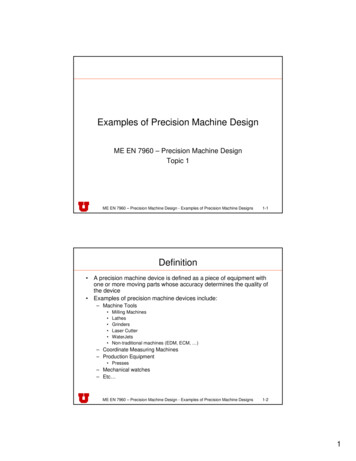
STM8 ADC internal hardware1AN2719STM8 ADC internal hardwareSTM8 family microcontrollers include an Analog to Digital Converter of the switchedcapacitor type. This ADC type uses the SAR (Successive Approximation Register) principle,by which the conversion is performed in several steps. The number of conversion steps isequal to the number of bits in the ADC converter.1.1SAR principleFigure 1 to Figure 6 show the first conversion steps.Figure 1.Basic schematic of switched-capacitor 64C/128C/128APR QDSbADCdataCLKADCclkCLRADCclkFigure 2.Sample C/64C/128C/128ASb2CVcomp 0VinEquivalent circuit:4/22A
AN2719STM8 ADC internal hardwareFigure 3.Hold C/64C/128C/128ASbVcomp - Vin2CAEquivalent circuit:Figure 4.Step 1 compare with 2C/64C/128C/128ASbVcomp - Vin Vref/2CVrefEquivalent circuit:CA5/22
STM8 ADC internal hardwareFigure 5.AN2719Step 2, if MSB 1 then compare with 3/4 /64C/128C/128ASbVcomp - Vin 3/4 VrefC/2VrefFigure 6.A3C/2Equivalent circuit:Step 2 if MSB 0 then compare with 1/4 /64C/128C/128ASbVcomp - Vin 1/4 Vref3C/2Equivalent circuit:6/22VrefC/2A
AN27191.2STM8 ADC internal hardwareADC clockThe ADC is driven by a clock derived from the MCU master clock through a programmabledivider. This allows you to select the ADC clock speed according to your applicationrequirements. The conversion and sampling speed depends on ADC clock. Eachconversion step (described in Figure 4 to Figure 6 ) is performed in one ADC clock cycle - so10-bit conversion takes 10 cycles. The sampling period is 3 clocks and the synchronisationperiod takes 1 clock. The total conversion time is actually 14 cycles.1.3Reference voltageThe reference voltage is either internally connected to analog power supply pins orconnected to external pins where you can connect a reference voltage source. Thisreference voltage connection option depends on the given STM8 package and STM8 devicetype. The reference voltage has big influence to ADC precision, therefore care must betaken with it in the application design (stability, noise, .).1.4MultiplexerThe ADC has an input multiplexer which is used to select one of the STM8 input pins as theanalog input to the ADC.7/22
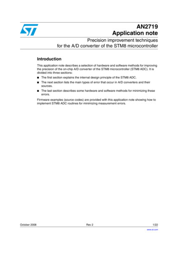
ADC errorsAN27192ADC errors2.1IntroductionThis chapter lists the main errors which have an effect on A/D conversion accuracy. Thesetypes of error occur in all A/D converters and conversion quality depends on eliminatingthem. You can find values for these errors specified in the ADC characteristics section of anySTM8 datasheet. The datasheets also include sections describing sources of error ormethods for minimizing them.2.2Linearity errors2.2.1Differential nonlinearityDifferential nonlinearity (DNL) shows how far a code is from a neighboring code. Thedistance is measured as a change in input voltage magnitude and then converted to LSBs.The best ADC performance is specified as "no missing codes". This means that if the inputvoltage is swept over its range, all output code combinations will appear at the converteroutput. A DNL error of 1LSB guarantees no missing codes. With a DNL equal to -1LSB,the ADC does not guarantee to have no missing codes. With a DNL greater than -1, thedevice has missing codes.Figure 7.DNL: no missing codesADC output[code]110101Real ADC100DNL - 0.5 LSBno missing code011010Ideal ADC001000Figure 8.Input voltage[V]DNL: missing codeADC output[code]110101Real ADC100011DNL - 1.5 LSBmissing code 0110100010008/22Ideal ADCInput voltage[V]
AN27192.2.2ADC errorsIntegral nonlinearityIntegral nonlinearity (INL) is defined as the integral of the DNL errors. So, good INLguarantees good DNL. The INL error shows how far from the ideal transfer function valuethe measured converter result is. For example, an INL error of /-2LSB in a 10-bit systemmeans the maximum nonlinearity error may be off by 2/1024 or 0.2%. Note that neither INLnor DNL errors can be calibrated or corrected easily.2.3Offset errorOffset and gain errors can easily be calibrated by the application firmware. First, apply zerovolts to the ADC input and perform a conversion, then the conversion result represents thezero offset error. Then perform a gain adjustment. A subsequent offset error calibration maybe required. A useful method for offset and gain calibration is the least square method(which calculates the smallest error in all the used range).2.4Gain errorGain error is defined as the full-scale error minus the offset error. Full-scale error ismeasured at the last ADC transition on the transfer-function curve and compared to theideal ADC transfer function.Gain error is easily corrected in firmware with this linear function:y (k1/k2).xwhere k1 is the slope of the ideal transfer function and k2 is the slope of the measuredtransfer function.Offset error and gain error can decrease dynamic range. For example this can be observed,if a full-scale input voltage is applied and the code obtained is 1010 instead of the ideal 1023(for a 10-bit converter), or if the full-scale code 1023 appears with an input voltage less thanfull-scale.Figure 9.Offset and gain errorADC output[code]110Gain errorReal ADCmax. code101100011Ideal ADC010001offset error000Input voltage[V]9/22
ADC errorsAN27192.5Hardware design errors2.5.1External resistance design errorThe input multiplexer has nonzero impedance (Rmpx max. 1kΩ). Sampling is done byswitch which has also nonzero impedance (Rsw max. 30kΩ). Both these impedances,together with the sampling capacitance (Csamp max. 3pF) and external signal sourceresistance (Rext), create a low pass filter. Therefore the external signal source impedance(Rext) must be designed so that this low pass filter cut-off frequency will be not too low inrelation to the ADC sampling time (Ts 3 ADC clocks).( R sw R mpx R ext ) C samp « T sFigure 10. Analog input circuitSTM8 ADCSWsampinputAINRextCsampIf the ADC converter has 10-bit precision (n 10) then the maximum precision is 1/2 LSBlevel (0.5/1024 from full range). So the acceptable error caused by charging Csamp throughall resistors is 0.5/1024 (during 3 cycles of fADC clock). Then the maximum resistor valueRmax Rext Rsw Rmpx is obtained from following equation:( Uc – Ui )error ---------------------- eUi3---------f ADC– --------------------------------R max C samp 2 1--------n3R max – --------1 2 f ADC C samp ln ---------- nfor worst case: fADC 2 MHz and required 10-bit resolution (n 10) the maximum serialresistor is:3R max – -------------------------------- 66kΩ6– 121 2( 2 10 ) ( 3 10 ) ln ------------- 1024and the maximum external resistor is:R ext R max – R sw – R mpx 66 – 30 – 1 35kΩThe external parasitic PCB and package capacitance must also be taken into account.Therefore the maximum resistance of external signal source Rext is lower, and in practiceRext 20 kΩ is suggested.10/22
AN27192.5.2ADC errorsReference voltage sourceOne of the biggest potential sources of errors in an ADC is the reference voltage. It isimportant to look at three reference voltage specifications: temperature drift, voltage noise,and load regulation (input resistance of reference input on STM8 ADC converter is 60 kΩ).2.5.3Temperature influenceTemperature has a big effect on ADC precision. Mainly two specifications are important:offset drift and gain drift. Those errors can be compensated in microcontroller firmware. Onemethod is to fully characterize the offset and gain drift and provide a lookup table in memoryto correct measurement due to temperature change. The ADC in each MCU device mustthen be compensated individually - therefore this calibration takes additional cost and time.The second method is to recalibrate the ADC when temperature change reaches givenvalues. The effect of temperature on ADC accuracy is usually not specified seperately formicrocontrollers because it is lower than other effects. It is included in the values for theother error types.2.5.4AC performanceUsually ADC performance is good only if input signals are from DC level up to Nyquistfrequency. This is because an ADC design contains not only resistors but also capacitors(and parasitic RLC elements). Therefore frequency response degrades ADC performance iffrequency increases. In case of AC measurement, the ADC frequency parameters must bestudied; mainly signal-to-noise ratio (SNR), total harmonic distortion (THD) and spuriousfree dynamic range (SFDR). Additional parameters can be signal-to-noise and distortionratio (SINAD) and effective number of bits (ENOB).11/22
Methods for precision improvement3Methods for precision improvement3.1IntroductionAN2719ADC converter precision is fixed by its principle, design and implementation but can be alsoimproved by several hardware and/or software methods. Hardware methods improve ADCresults by changing the environment around the ADC (PCB design, RC filters, .) to obtainmore accurate ADC output. Software methods try to improve the raw ADC results bypostprocessing methods. Some CPU power is required to perform these methods, whichcan be implemented in the microcontroller firmware.3.2Hardware methods 3.2.1Analog zooming (use appropriate VREF voltage and VREF offset):–select reference voltage between input signal ranges–gives full ADC range - min. voltage per bitWhite noise added to measured signal:–wobbling of input signal over several bits gives the opportunity to use averaging (ifinput signal is very stable)–white noise gives independence from sampling frequencyGood hardware design:–grounding–reference voltage filtering–supply filtering–preamplifier usage–frequency independence– Analog zoomingAnalog zooming is method which improves precision by proper selection of the referencevoltage. The reference voltage is selected in the expected range of the signal to bemeasured.If the measured signal has an offset, then the reference voltage should also have a similaroffset. If the measured signal has defined maximum amplitude, then the reference voltageshould also have a similar maximum value. By matching this reference voltage to themeasurement signal range we obtain the maximum possible resolution using the full A/Dconverter output range.In the STM8 ADC the reference voltage is connected to external pins VREF and VREF-.This makes it possible to match the reference voltage to the measured signal range.To VREF- pin you can connect the minimum measured voltage and to VREF pin youconnect the maximum measured voltage. Take care to respect the minimum and maximumallowed reference signal levels - these values are specified in the datasheet for the relatedSTM8 device type.12/22
AN27193.2.2Methods for precision improvementAdding white noiseThis method combines hardware and software techniques to improve precision. From asoftware point of view, this method uses averaging and from a hardware point of view, ituses signal modification/spreading.Averaging can be used in cases where the input signal is noisy (some signal change isnecessary in order to be able to calculate an average) and the requirement is to obtain themean value of a signal. A problem can appear when input signal is a very stable voltagewithout noise. In this case, when the input signal is measured, each sample is the same.This is because the input signal level is somewhere between two ADC word levels (e.g.between 0x14A and 0x14B). Therefore it is not possible to determine the input voltage levelmore precisely (e.g. if the level is near to 0x14A or near to 0x14B level). The solution is toadd noise to the input signal which pushes its level across 1-bit ADC level (so that the signallevel changes below 0x14A and above 0x14B level). This causes the ADC results to vary.Applying software averaging to the different ADC results, produces the mean value of theoriginal input signal. This method is also called oversampling and/or dithering.Adding a white noise signal gives 0.5LSB more each time you double the number ofsamples. By adding triangle noise, you get 1LSB, which is more efficient. The noise sourcecan be the microcontroller itself.This can be implemented using a noise generator with RC coupling of this noise to the inputsignal. Care must be taken to not modify the mean value of the original input signal - socapacitive coupling is used.A very simple implementation is to design the white noise source as a square (or triangle)source which is generated directly by the STM8 microcontroller (Figure 11).Figure 11. Simple white noise source using a microcontroller outputVddUouttR1OUTCR2MCUAINVinUinVint13/22
Methods for precision improvement3.2.3AN2719Hardware design rulesGood hardware design can remove or minimize many external influences on the measuredsignal and measuring device. Therefore good design is also a method of improvingprecision, or rather a method of minimizing additional errors caused by the externalhardware. The following lists the main rules for minimizing external influences.Grounding:Care must be taken in the design of the PCB grounding. Ground paths on a PCB havenonzero resistance (and impedance) therefore current flowing through these pathsgenerates a voltage drop. This voltage drop changes the voltages at points that areimportant for the ADC. For example it changes the reference voltage on the microcontrollerpins slightly or influences the input signal on the microcontroller analog input pins. Gooddesign minimizes this voltage drop. Methods of doing this are: minimizing the ground pathimpedance and minimizing the current through important ground paths (topology).To minimize ground impedance: use massive ground paths. To minimize current throughsensitive connections: use star topology, use independent PCB lines from input signal pinsto microcontroller analog inputs, use independent PCB lines from the reference voltagesource to microcontroller reference voltage inputs. Simply: supply current should not flowthrough signal ground - use signal ground and power ground in design.Voltage filtering:To minimize any external influences on the precise voltage levels used by the ADC, it isgood to use filters on these voltage sources. Good filters must be applied on the referencevoltage and on the supply voltage. Filter design depends on the noise amplitude present onthe voltage sources, the external noise disturbance and the required precision.Preamplifier usage:If the measured signal is too small (in comparison to the ADC range) then it is good to useexternal preamplifier. This amplifier can fit the input signal range to the ADC range and canalso insert offsets between input signal and ADC input. Care must be taken in thepreamplifier design in order not to generate additional errors (for example additional offset,amplifier gain stability, linearity, frequency response, . ).Frequency independence:In cases where an AC signal is measured, frequency is an important characteristic of theinput signal path. When measuring fast changes in the input signal then the frequencyresponse of the signal path must be flat, even at high frequencies. The parasitic resistanceand parasitic capacitance on PCB signal paths must be minimized. Otherwise, whenmeasuring DC signal levels, adding an RC filter to the input signal data path can improverobustness against external noise.14/22
AN27193.3Methods for precision improvementSoftware methods Averaging samples:– 3.3.1averaging decreases speed but can give improved accuracyDigital filtering (50/60 Hz suppression from DC value)–set proper sampling frequency (the trigger from Timer1 is useful in this case)–perform software post-processing on sampled data (comb filter)Fast Fourier Transform (FFT) for AC measurements:–to show harmonic parts in measured signal–slower, due to the use of more computation powerCalibration of ADC: offset, gain, bit weight calibration–decreases internal ADC errors–internal ADC structure must be knownAveraging samplesThe principle of this method is to increase ADC precision but decrease ADC conversionspeed. If the measured analog signal produces unstable ADC values, then the mean valueof the given input signal can be obtained by averaging a set of values. Variation can becaused by signal noise or noise generated by the microcontroller itself (high speed digitalsignals capacitively coupled to the analog input signal).Averaging is performed by choosing an appropriate number of samples to be averaged. Thisnumber depends on the required precision, minimum conversion speed and the level ofother ADC errorsl (if another error has a greater influence on ADC precision, then increasingthe number of averaging values has no effect on total measurement precision).The advantage of this method is improving precision without any hardware changes. Thedisadvantages are lower conversion speed and therefore also lower frequency response (itis equivalent to decreasing effective sampling frequency). Another disadvantage is the needfor an analog anti-aliasing filter.3.3.2Digital signal filteringThis is modern method which uses digital signal processing techniques. In principle,averaging is also a simple digital filter with a specific frequency response. But if the noisefrequency spectrum is known, a digital filter can be designed which minimizes noiseinfluence and maximizes ADC frequency response. For example, if the noise in themeasured signal is coming from the 50 Hz power lines, then an appropriate digital filter canmainly suppress the 50 Hz frequency and deliver a precise 10 Hz input signal response.The disadvantage of this method is that it needs sufficient microcontroller processing powerand resources: CPU speed, RAM/ROM memory usage.3.3.3FFT for AC measurementIn some specific cases the application needs to know the amplitude of an AC signal with agiven frequency. In this case the effective value of an AC signal can also be obtained byusing a relatively slow sampling speed (in comparison to the measured signal frequency).For example, when measuring an AC mains signal (which is near-to-sinusoidal and hasrelatively low harmonics content), it is sufficient to choose a sampling frequency 32 timesgreater than the mains frequency (50 Hz). In this case you can obtain harmonics up to the15/22
Methods for precision improvementAN271915th order. The amplitude of 15th harmonics in the main signal is very small (the next orderharmonics can be neglected). The calculated effective value of the mains signal can beobtained with high precision because the effective values of harmonics are added to thetotal AC harmonic value as:U ef 222U1 U2 UnSo if the 15th harmonics amplitude is only 1% (0.01) from 1st harmonics (50 Hz) then itscontribution to the total effective value will be only 0.01% (because of above equation square addition: 0.012 0.0001).The principle of this method is therefore to sample the AC signal with a known frequencyand then perform FFT postprocessing on the data of each measured period. Because thenumber of sampling points per measured signal period is small (32 points for example) thenthe performance needed for FFT processing is not so high (only 32-point FFT for example).If there is no requirement for real-time processing, for example, with a stable input signalshape, and measuring only one period per second, as in the case of the mains signal, thenFFT can be calculated even by an 8-bit microcontroller.Advantages: this method is good for AC measurement of a stable input signal. Thedisadvantage is the requirement for precise signal sampling. The frequency of the measuredsignal must be known and the ADC sampling frequency must be set exactly as a 2nmultiplier of the measured frequency. The input signal frequency can be measured byanother method. The ADC sampling frequency can be tuned by programming the prescalerand MCU master clock or interpolation can used to insert sample points at the requiredfrequency if sampling is performed with an inaccurate clock.3.3.4ADC calibrationThis method requires knowledge of internal ADC structure and how the ADC converter isimplemented inside the microcontroller. This knowledge is necessary in order to design aphysical/mathematical model of the ADC implementation. In case of an unknown ADCimplementation we can use standard models - linear or polynomic.A proper physical model (which is usually a schematic diagram) can be used as the base fordescribing it mathematically. From the mathematical model each element in the model canbe obtained by set of equations (for example, resistor values which represent bit weights).To solve these equations is necessary to perform a set of practical measurements andobtain a set of solvable equations (for example, measurement: input signal versus theproper ADC digital output words).From the measured values and mathematical computation of the model, all known values ofmodel elements (resistors, voltages, capacitors,.) can be put into the schematic diagram.So instead of the ADC converter schematic with the designed values you obtain an ADCconverter schematic with the real values for a given microcontroller.Computed model parameters can be stored in the microcontroller memory after calibrationand used in postprocessing to correct ADC values.16/22
AN27194Design rules for minimizing errorsDesign rules for minimizing errorsADC precision can only be significantly improved if external influences on the measurementare minimized. Therefore any precision improvement method also includes rules for correctdesign.Main design rules for minimizing design errors: Grounding of analog/digital power:– star topologyVDDA, VSSA filtering:–RC, LC filtering–avoid noise from noisy digital powerVREF selection - offset, value, precision:–reference voltage source precision and stability matched to application precisionrequirements and ADC capability–reference voltage source value and precision in line with the expected measuredrangeSource impedance vs. input impedance knowledge:–use input buffers for measured signal (if source impedance is too high)–impedance in relation with required conversion speedExternal preamplifier usage:–for low (and also high) level signals–amplifier speed and precision properties–amplifier dependency on frequency Select appropriate ADC mode, speed, trigger Software methods: averaging, FFT, 17/22
Conclusion5AN2719ConclusionThe Analog to Digital Converter (ADC) in the STM8 microcontroller family is a standard ADCconverter which can have common errors. To minimize errors and improve precision, themain methods and application design rules have been described. You can apply thesemethods to your application.The choice of method depends on the application requirements and is always a compromisebetween speed/precision, enough computation power and design topology. Publishedmethods lead to precision improvement but strongly depend on the ADC basic properties.18/22
AN2719Appendix - source code examples6Appendix - source code examples6.1Project code exampleA firmware package is linked with this document. It contains source codes in C-languagewhich give examples of some of the precision improvement methods described in thisapplication note. This complete project is designed for the ST Visual Develop (STVD)development environment and Cosmic compiler and using the STM8 evaluation board. Withthese examples you can see how the method is implemented in practice and you can test itby comparing ADC precision with the improvement method and without it.Package name: STM8 ADC improvement.zipProject name: STM8 ADC improvement.stw6.2Source code descriptionThe example consists of a complete STVD project. This project contains source codes infiles:main.cmain program file (MCU initialization, main program loop)ADCAveraging.ctesting - each file for given method (uses STM8 DCWhiteNoise.cFFT.cFilter50Hz.cmono lcd.cdriver for writing to LCD display (on STM8 evaluation board)stm8 interrupt vector.ccontains interrupt table address definitionADCAveraging.hheaders for ADC precision improvements CWhiteNoise.hFFT.hFilter50Hz.hglobaldefFFT.hmono lcd.hlist of LCD functionsstm8 conf.hconfiguration of STM8 library19/22
Appendix - source code examples6.2.1AN2719Program flowIn the main.c file is the main program loop - in function main(). At the beginning is the basicMCU initialization: GPIO pins (LED diodes, buttons), CPU clock, interrupts. Then the maintesting loop begins - it consists of the ADC initialization and series of steps (methods).Each test step contains a write to the LCD display to display information about the runningtest and then contains the test routine itself. The test routines are provided in listed files each file for each method. To continue from one test to the next, the user must press abutton (joystick select button on evaluation board). After all tests are done, then the ADC isreconfigured to higher speed and the test loop runs again.Tests a
Precision improvement techniques for the A/D converter of the STM8 microcontroller Introduction This application note describes a selection of hardware and software methods for improving the precision of the on-chip A/D converter of the STM8 micro