Transcription
Precision CoolingFor Business-Critical Continuity Liebert Challenger 3000/Liebert Challenger ITR with Liebert iCOM ControlOperation & Maintenance Manual - 50 & 60Hz
TABLE OF CONTENTSIMPORTANT SAFETY INSTRUCTIONS . . . . . . . . . . . . . . . . . . . . . . . . . . . . . . . . INSIDE FRONT COVERSAVE THESE INSTRUCTIONS . . . . . . . . . . . . . . . . . . . . . . . . . . . . . . . . . . . . . . . . . . . . . . . . .11.0INTRODUCTION . . . . . . . . . . . . . . . . . . . . . . . . . . . . . . . . . . . . . . . . . . . . . . . . . . . . . . . . . .31.1System Descriptions . . . . . . . . . . . . . . . . . . . . . . . . . . . . . . . . . . . . . . . . . . . . . . . . . . . . . . . . . . 31.1.11.1.21.1.3Compressorized Systems . . . . . . . . . . . . . . . . . . . . . . . . . . . . . . . . . . . . . . . . . . . . . . . . . . . . . . . 3GLYCOOL (Chilled Glycol Cooling) Systems. . . . . . . . . . . . . . . . . . . . . . . . . . . . . . . . . . . . . . 3Chilled Water Systems. . . . . . . . . . . . . . . . . . . . . . . . . . . . . . . . . . . . . . . . . . . . . . . . . . . . . . . . . 32.0STARTUP . . . . . . . . . . . . . . . . . . . . . . . . . . . . . . . . . . . . . . . . . . . . . . . . . . . . . . . . . . . . . .42.1Startup Procedure . . . . . . . . . . . . . . . . . . . . . . . . . . . . . . . . . . . . . . . . . . . . . . . . . . . . . . . . . . . 43.0OPERATION WITH LIEBERT ICOM CONTROL . . . . . . . . . . . . . . . . . . . . . . . . . . . . . . . . . . .63.1Features . . . . . . . . . . . . . . . . . . . . . . . . . . . . . . . . . . . . . . . . . . . . . . . . . . . . . . . . . . . . . . . . . . . 64.0LIEBERT ICOM DISPLAY COMPONENTS AND FUNCTIONS . . . . . . . . . . . . . . . . . . . . . . . . . . .74.1Navigating Through the Liebert iCOM Display . . . . . . . . . . . . . . . . . . . . . . . . . . . . . . . . . . . . 94.1.14.1.24.1.34.1.4Control Interface—Three Main Menus . . . . . . . . . . . . . . . . . . . . . . . . . . . . . . . . . . . . . . . . . . .Accessing Menus and Settings. . . . . . . . . . . . . . . . . . . . . . . . . . . . . . . . . . . . . . . . . . . . . . . . . .Entering the Password . . . . . . . . . . . . . . . . . . . . . . . . . . . . . . . . . . . . . . . . . . . . . . . . . . . . . . . .Accessing Submenus . . . . . . . . . . . . . . . . . . . . . . . . . . . . . . . . . . . . . . . . . . . . . . . . . . . . . . . . .101011124.2Changing Operational Settings . . . . . . . . . . . . . . . . . . . . . . . . . . . . . . . . . . . . . . . . . . . . . . . . 144.3Changing Liebert iCOM’s Display Settings . . . . . . . . . . . . . . . . . . . . . . . . . . . . . . . . . . . . . . 154.4Graphical Data Record. . . . . . . . . . . . . . . . . . . . . . . . . . . . . . . . . . . . . . . . . . . . . . . . . . . . . . . 164.5Liebert iCOM Service Menu Icons and Legend . . . . . . . . . . . . . . . . . . . . . . . . . . . . . . . . . . . 164.6Wiring for Unit-to-Unit Communications—U2U . . . . . . . . . . . . . . . . . . . . . . . . . . . . . . . . . . 174.6.14.6.2Liebert iCOM U2U Ethernet Network . . . . . . . . . . . . . . . . . . . . . . . . . . . . . . . . . . . . . . . . . . . 17Wiring a Liebert iCOM U2U Network . . . . . . . . . . . . . . . . . . . . . . . . . . . . . . . . . . . . . . . . . . . 184.7Entering Network Setup Information . . . . . . . . . . . . . . . . . . . . . . . . . . . . . . . . . . . . . . . . . . . 254.8Viewing Multiple Units with a Networked Large Display. . . . . . . . . . . . . . . . . . . . . . . . . . . 265.0OPERATION . . . . . . . . . . . . . . . . . . . . . . . . . . . . . . . . . . . . . . . . . . . . . . . . . . . . . . . . . . .275.1Single Unit Functions . . . . . . . . . . . . . . . . . . . . . . . . . . . . . . . . . . . . . . . . . . . . . . . . . . . . . . . 275.1.15.1.25.1.35.2Control Types . . . . . . . . . . . . . . . . . . . . . . . . . . . . . . . . . . . . . . . . . . . . . . . . . . . . . . . . . . . . . . 305.2.15.2.25.2.36.0Unit/Fan Control . . . . . . . . . . . . . . . . . . . . . . . . . . . . . . . . . . . . . . . . . . . . . . . . . . . . . . . . . . . . 27General Compressor Requirements. . . . . . . . . . . . . . . . . . . . . . . . . . . . . . . . . . . . . . . . . . . . . . 28Compressor Timing . . . . . . . . . . . . . . . . . . . . . . . . . . . . . . . . . . . . . . . . . . . . . . . . . . . . . . . . . . 29Proportional Control. . . . . . . . . . . . . . . . . . . . . . . . . . . . . . . . . . . . . . . . . . . . . . . . . . . . . . . . . . 30PI Control . . . . . . . . . . . . . . . . . . . . . . . . . . . . . . . . . . . . . . . . . . . . . . . . . . . . . . . . . . . . . . . . . . 30Intelligent Control (Chilled Water Only) . . . . . . . . . . . . . . . . . . . . . . . . . . . . . . . . . . . . . . . . . 31ALARM DESCRIPTIONS . . . . . . . . . . . . . . . . . . . . . . . . . . . . . . . . . . . . . . . . . . . . . . . . . . . 32i
6.1Standard Alarms . . . . . . . . . . . . . . . . . . . . . . . . . . . . . . . . . . . . . . . . . . . . . . . . . . . . . . . . . . . .106.1.116.1.126.1.136.1.146.1.156.2Change Filter . . . . . . . . . . . . . . . . . . . . . . . . . . . . . . . . . . . . . . . . . . . . . . . . . . . . . . . . . . . . . . .Compressor Overload . . . . . . . . . . . . . . . . . . . . . . . . . . . . . . . . . . . . . . . . . . . . . . . . . . . . . . . . .High Head Pressure . . . . . . . . . . . . . . . . . . . . . . . . . . . . . . . . . . . . . . . . . . . . . . . . . . . . . . . . . .High Humidity . . . . . . . . . . . . . . . . . . . . . . . . . . . . . . . . . . . . . . . . . . . . . . . . . . . . . . . . . . . . . .High Humidity and Low Humidity (Simultaneously) . . . . . . . . . . . . . . . . . . . . . . . . . . . . . . .High Temperature . . . . . . . . . . . . . . . . . . . . . . . . . . . . . . . . . . . . . . . . . . . . . . . . . . . . . . . . . . .High Temperature and Low Temperature (Simultaneously) . . . . . . . . . . . . . . . . . . . . . . . . .Humidifier Problem . . . . . . . . . . . . . . . . . . . . . . . . . . . . . . . . . . . . . . . . . . . . . . . . . . . . . . . . . .Loss of Air Flow . . . . . . . . . . . . . . . . . . . . . . . . . . . . . . . . . . . . . . . . . . . . . . . . . . . . . . . . . . . . .Loss of Power . . . . . . . . . . . . . . . . . . . . . . . . . . . . . . . . . . . . . . . . . . . . . . . . . . . . . . . . . . . . . . .Low Humidity . . . . . . . . . . . . . . . . . . . . . . . . . . . . . . . . . . . . . . . . . . . . . . . . . . . . . . . . . . . . . . .Low Suction Pressure. . . . . . . . . . . . . . . . . . . . . . . . . . . . . . . . . . . . . . . . . . . . . . . . . . . . . . . . .Low Temperature . . . . . . . . . . . . . . . . . . . . . . . . . . . . . . . . . . . . . . . . . . . . . . . . . . . . . . . . . . . .Main Fan Overload. . . . . . . . . . . . . . . . . . . . . . . . . . . . . . . . . . . . . . . . . . . . . . . . . . . . . . . . . . .Short Cycle . . . . . . . . . . . . . . . . . . . . . . . . . . . . . . . . . . . . . . . . . . . . . . . . . . . . . . . . . . . . . . . . .323233333333333334343434343434Optional Alarms . . . . . . . . . . . . . . . . . . . . . . . . . . . . . . . . . . . . . . . . . . . . . . . . . . . . . . . . . . . . 356.2.16.2.26.2.36.2.46.2.5Loss of Water Flow . . . . . . . . . . . . . . . . . . . . . . . . . . . . . . . . . . . . . . . . . . . . . . . . . . . . . . . . . . .Smoke Detected . . . . . . . . . . . . . . . . . . . . . . . . . . . . . . . . . . . . . . . . . . . . . . . . . . . . . . . . . . . . .Standby GC Pump On . . . . . . . . . . . . . . . . . . . . . . . . . . . . . . . . . . . . . . . . . . . . . . . . . . . . . . . .Standby Unit On. . . . . . . . . . . . . . . . . . . . . . . . . . . . . . . . . . . . . . . . . . . . . . . . . . . . . . . . . . . . .Water Under Floor . . . . . . . . . . . . . . . . . . . . . . . . . . . . . . . . . . . . . . . . . . . . . . . . . . . . . . . . . . .35353535356.3Set Alarms—User Menus. . . . . . . . . . . . . . . . . . . . . . . . . . . . . . . . . . . . . . . . . . . . . . . . . . . . . 357.0COMPONENT OPERATION AND MAINTENANCE . . . . . . . . . . . . . . . . . . . . . . . . . . . . . . . . . . 367.1System Testing . . . . . . . . . . . . . . . . . . . . . . . . . . . . . . . . . . . . . . . . . . . . . . . . . . . . . . . . . . . . . 367.1.1Environmental Control Functions . . . . . . . . . . . . . . . . . . . . . . . . . . . . . . . . . . . . . . . . . . . . . . . 367.2Filters . . . . . . . . . . . . . . . . . . . . . . . . . . . . . . . . . . . . . . . . . . . . . . . . . . . . . . . . . . . . . . . . . . . . 387.3Blower Package . . . . . . . . . . . . . . . . . . . . . . . . . . . . . . . . . . . . . . . . . . . . . . . . . . . . . . . . . . . . 397.3.17.3.27.3.37.4Refrigeration System . . . . . . . . . . . . . . . . . . . . . . . . . . . . . . . . . . . . . . . . . . . . . . . . . . . . . . . . .107.4.117.5Suction Pressure. . . . . . . . . . . . . . . . . . . . . . . . . . . . . . . . . . . . . . . . . . . . . . . . . . . . . . . . . . . . .Discharge Pressure. . . . . . . . . . . . . . . . . . . . . . . . . . . . . . . . . . . . . . . . . . . . . . . . . . . . . . . . . . .Superheat . . . . . . . . . . . . . . . . . . . . . . . . . . . . . . . . . . . . . . . . . . . . . . . . . . . . . . . . . . . . . . . . . .Thermostatic Expansion Valve . . . . . . . . . . . . . . . . . . . . . . . . . . . . . . . . . . . . . . . . . . . . . . . . .Hot Gas Bypass Valve—Not Available on Digital Scroll Units . . . . . . . . . . . . . . . . . . . . . . . .Air-Cooled Condenser. . . . . . . . . . . . . . . . . . . . . . . . . . . . . . . . . . . . . . . . . . . . . . . . . . . . . . . . .Water/Glycol-Cooled Condensers. . . . . . . . . . . . . . . . . . . . . . . . . . . . . . . . . . . . . . . . . . . . . . . .Motorized Ball Valve—Digital Scroll Compressor . . . . . . . . . . . . . . . . . . . . . . . . . . . . . . . . . .Regulating Valve—Scroll Compressor . . . . . . . . . . . . . . . . . . . . . . . . . . . . . . . . . . . . . . . . . . .Drycooler Settings . . . . . . . . . . . . . . . . . . . . . . . . . . . . . . . . . . . . . . . . . . . . . . . . . . . . . . . . . . .Compressor Oil . . . . . . . . . . . . . . . . . . . . . . . . . . . . . . . . . . . . . . . . . . . . . . . . . . . . . . . . . . . . . .4040404141424343444646Compressor Replacement. . . . . . . . . . . . . . . . . . . . . . . . . . . . . . . . . . . . . . . . . . . . . . . . . . . . . 477.5.17.5.27.5.37.6Fan Impellers and Bearings. . . . . . . . . . . . . . . . . . . . . . . . . . . . . . . . . . . . . . . . . . . . . . . . . . . . 39Belt . . . . . . . . . . . . . . . . . . . . . . . . . . . . . . . . . . . . . . . . . . . . . . . . . . . . . . . . . . . . . . . . . . . . . . . 39Air Distribution . . . . . . . . . . . . . . . . . . . . . . . . . . . . . . . . . . . . . . . . . . . . . . . . . . . . . . . . . . . . . 39Compressor Functional Check . . . . . . . . . . . . . . . . . . . . . . . . . . . . . . . . . . . . . . . . . . . . . . . . . . 47Standard Scroll Compressor Replacement . . . . . . . . . . . . . . . . . . . . . . . . . . . . . . . . . . . . . . . . 48Digital Scroll Compressor Replacement Procedure . . . . . . . . . . . . . . . . . . . . . . . . . . . . . . . . . 49Facility Fluid and Piping Maintenance for Water and Glycol Systems . . . . . . . . . . . . . . . . 49ii
7.7Humidifier. . . . . . . . . . . . . . . . . . . . . . . . . . . . . . . . . . . . . . . . . . . . . . . . . . . . . . . . . . . . . . . . . 507.7.17.7.2Infrared Humidifier . . . . . . . . . . . . . . . . . . . . . . . . . . . . . . . . . . . . . . . . . . . . . . . . . . . . . . . . . . 50Steam Generating Humidifier . . . . . . . . . . . . . . . . . . . . . . . . . . . . . . . . . . . . . . . . . . . . . . . . . . 518.0TROUBLESHOOTING . . . . . . . . . . . . . . . . . . . . . . . . . . . . . . . . . . . . . . . . . . . . . . . . . . . . . 559.0MONTHLY MAINTENANCE INSPECTION CHECKLIST . . . . . . . . . . . . . . . . . . . . . . . . . . . . . . . 6110.0SEMIANNUAL MAINTENANCE INSPECTION CHECKLIST . . . . . . . . . . . . . . . . . . . . . . . . . . . . 62FIGURESFigure 1Figure 2Figure 3Figure 4Figure 5Figure 6Figure 7Figure 8Figure 9Figure 10Figure 11Figure 12Figure 13Figure 14Figure 15Figure 16Figure 17Figure 18Figure 19Figure 20Figure 21Figure 22Figure 23Figure 24Figure 25Figure 26Figure 27Liebert iCOM components . . . . . . . . . . . . . . . . . . . . . . . . . . . . . . . . . . . . . . . . . . . . . . . . . . . . . . . . . 6Liebert iCOM display components . . . . . . . . . . . . . . . . . . . . . . . . . . . . . . . . . . . . . . . . . . . . . . . . . . . 7Liebert iCOM default screen symbols . . . . . . . . . . . . . . . . . . . . . . . . . . . . . . . . . . . . . . . . . . . . . . . . 8Liebert iCOM default home screen—Graphical view . . . . . . . . . . . . . . . . . . . . . . . . . . . . . . . . . . . . 9Liebert iCOM default home screen—Simple view . . . . . . . . . . . . . . . . . . . . . . . . . . . . . . . . . . . . . . 9Entering the password . . . . . . . . . . . . . . . . . . . . . . . . . . . . . . . . . . . . . . . . . . . . . . . . . . . . . . . . . . . 11Menu tree—Large and small displays, stand-alone or networked. . . . . . . . . . . . . . . . . . . . . . . . . 13Liebert iCOM User Menu icons . . . . . . . . . . . . . . . . . . . . . . . . . . . . . . . . . . . . . . . . . . . . . . . . . . . . 14Display setup screen . . . . . . . . . . . . . . . . . . . . . . . . . . . . . . . . . . . . . . . . . . . . . . . . . . . . . . . . . . . . . 15Temperature graph . . . . . . . . . . . . . . . . . . . . . . . . . . . . . . . . . . . . . . . . . . . . . . . . . . . . . . . . . . . . . . 16Liebert iCOM Service Menu icons . . . . . . . . . . . . . . . . . . . . . . . . . . . . . . . . . . . . . . . . . . . . . . . . . . 16U2U network setup diagram . . . . . . . . . . . . . . . . . . . . . . . . . . . . . . . . . . . . . . . . . . . . . . . . . . . . . . 19Liebert iCOM wiring—Unit as shipped . . . . . . . . . . . . . . . . . . . . . . . . . . . . . . . . . . . . . . . . . . . . . . 21Wiring a small display for U2U network operation . . . . . . . . . . . . . . . . . . . . . . . . . . . . . . . . . . . . 22Wiring a large display for U2U network operation. . . . . . . . . . . . . . . . . . . . . . . . . . . . . . . . . . . . . 23Liebert iCOM input-output control board . . . . . . . . . . . . . . . . . . . . . . . . . . . . . . . . . . . . . . . . . . . . 24Control board U2U network setup screen . . . . . . . . . . . . . . . . . . . . . . . . . . . . . . . . . . . . . . . . . . . . 25Liebert iCOM display U2U network setup screen . . . . . . . . . . . . . . . . . . . . . . . . . . . . . . . . . . . . . 25Menu tree—Large display, networked. . . . . . . . . . . . . . . . . . . . . . . . . . . . . . . . . . . . . . . . . . . . . . . 26Start-stop priority switches . . . . . . . . . . . . . . . . . . . . . . . . . . . . . . . . . . . . . . . . . . . . . . . . . . . . . . . 27Liebert leak detection units . . . . . . . . . . . . . . . . . . . . . . . . . . . . . . . . . . . . . . . . . . . . . . . . . . . . . . . 37Recommended liquid sensor locations . . . . . . . . . . . . . . . . . . . . . . . . . . . . . . . . . . . . . . . . . . . . . . . 37Outdoor fan/condenser configuration. . . . . . . . . . . . . . . . . . . . . . . . . . . . . . . . . . . . . . . . . . . . . . . . 42Johnson Controls valve adjustment. . . . . . . . . . . . . . . . . . . . . . . . . . . . . . . . . . . . . . . . . . . . . . . . . 44Metrex valve adjustment . . . . . . . . . . . . . . . . . . . . . . . . . . . . . . . . . . . . . . . . . . . . . . . . . . . . . . . . . 45Infrared humidifier lamps . . . . . . . . . . . . . . . . . . . . . . . . . . . . . . . . . . . . . . . . . . . . . . . . . . . . . . . . 50Steam generating humidifier . . . . . . . . . . . . . . . . . . . . . . . . . . . . . . . . . . . . . . . . . . . . . . . . . . . . . . 51iii
TABLESTable 1Table 2Table 3Table 4Table 5Table 6Table 7Table 8Table 9Table 10Table 11Table 12Table 13Table 14Table 15Table 16Table 17Table 18Table 19Keyboard icons and functions. . . . . . . . . . . . . . . . . . . . . . . . . . . . . . . . . . . . . . . . . . . . . . . . . . . . . . . 8Sample Liebert iCOM network configurations . . . . . . . . . . . . . . . . . . . . . . . . . . . . . . . . . . . . . . . . 17Set alarms—User Menus . . . . . . . . . . . . . . . . . . . . . . . . . . . . . . . . . . . . . . . . . . . . . . . . . . . . . . . . . 35Zone leak detection kit installation scenarios . . . . . . . . . . . . . . . . . . . . . . . . . . . . . . . . . . . . . . . . . 38Recommended free area ft2 (m2) for grilles or perforated panels at output velocities of 550and 600 fpm (2.8 and 3.1 m/s) . . . . . . . . . . . . . . . . . . . . . . . . . . . . . . . . . . . . . . . . . . . . . . . . . . . . . 39Suction pressures - R407c. . . . . . . . . . . . . . . . . . . . . . . . . . . . . . . . . . . . . . . . . . . . . . . . . . . . . . . . . 40Discharge pressures . . . . . . . . . . . . . . . . . . . . . . . . . . . . . . . . . . . . . . . . . . . . . . . . . . . . . . . . . . . . . 40Water/glycol system conditions requiring optional settings for aquastats . . . . . . . . . . . . . . . . . . 46Aquastat settings—two-fan through four-fan drycoolers . . . . . . . . . . . . . . . . . . . . . . . . . . . . . . . . 46Compressor oil types . . . . . . . . . . . . . . . . . . . . . . . . . . . . . . . . . . . . . . . . . . . . . . . . . . . . . . . . . . . . . 46Humidifier canister part numbers . . . . . . . . . . . . . . . . . . . . . . . . . . . . . . . . . . . . . . . . . . . . . . . . . . 53Blower troubleshooting . . . . . . . . . . . . . . . . . . . . . . . . . . . . . . . . . . . . . . . . . . . . . . . . . . . . . . . . . . . 55Chilled water troubleshooting . . . . . . . . . . . . . . . . . . . . . . . . . . . . . . . . . . . . . . . . . . . . . . . . . . . . . 55Compressor and refrigeration system troubleshooting. . . . . . . . . . . . . . . . . . . . . . . . . . . . . . . . . . 56Dehumidification troubleshooting . . . . . . . . . . . . . . . . . . . . . . . . . . . . . . . . . . . . . . . . . . . . . . . . . . 58Glycol pump troubleshooting . . . . . . . . . . . . . . . . . . . . . . . . . . . . . . . . . . . . . . . . . . . . . . . . . . . . . . 58Infrared humidifier troubleshooting . . . . . . . . . . . . . . . . . . . . . . . . . . . . . . . . . . . . . . . . . . . . . . . . 58Steam generating humidifier troubleshooting . . . . . . . . . . . . . . . . . . . . . . . . . . . . . . . . . . . . . . . . 59Reheat troubleshooting. . . . . . . . . . . . . . . . . . . . . . . . . . . . . . . . . . . . . . . . . . . . . . . . . . . . . . . . . . . 60iv
IMPORTANT SAFETY INSTRUCTIONSSAVE THESE INSTRUCTIONSThis manual contains important safety instructions that should be followed during the installationand maintenance of the Liebert Challenger 3000/Liebert Challenger ITR with Liebert iCOM. Readthis manual thoroughly before attempting to install or operate this unit.Only qualified personnel should move, install or service this equipment.Adhere to all warnings, cautions and installation, operating and safety instructions on the unit and inthis manual. Follow all operating and user instructions.! WARNINGRisk of electric shock. Can cause injury or death.Disconnect local and remote power supplies before working within.Before proceeding with installation, read all instructions, verify that all the parts are includedand check the nameplate to be sure the voltage matches available utility power.The Liebert iCOM microprocessor does not isolate power from the unit, even in the “Unit Off”mode. Some internal components require and receive power even during the “Unit Off” modeof Liebert iCOM control.The factory-supplied optional disconnect switch is inside the unit. The line side of this switchcontains live high-voltage.The only way to ensure that there is NO voltage inside the unit is to install and open a remotedisconnect switch. Refer to unit electrical schematic.Follow all local codes.! WARNINGRisk of explosive discharge from high-pressure refrigerant. Can cause injury or death.This unit contains fluids and gases under high pressure. Relieve pressure before working withpiping.! WARNINGRisk of refrigerant system rupture or explosion from overpressurization. Can causeequipment damage, injury or death.Local building or plumbing codes may require that a fusible plug or other type of pressurerelief device be installed in the system.For systems requiring EU CE compliance (50Hz), the system installer must provide andinstall a discharge pressure relief valve rated for a maximum of 500psig (34bar) in the highside refrigerant circuit. Do not install a shutoff valve between the compressor and the fieldinstalled relief valve. The pressure relief valve must be CE certified to the EU PressureEquipment Directive by an EU “Notified Body.”NOTEThe Liebert indoor cooling unit has a factory-installed high pressure safety switch in the highside refrigerant circuit. A pressure relief valve is provided with Liebert Lee-Temp condensers.Consult your local building code to determine if the Liebert Fan Speed Control and VFDcondensers will require field-provided pressure-relief devices. A fusible plug kit for Liebert FSCand VFD condensers is available for field installation.1
! WARNINGRisk of high-speed moving parts. Can cause injury or death.Disconnect all local and remote electric power supplies before working in the unit.Do not operate upflow units without installing a plenum, ductwork or guard over the bloweropening(s) on the top of the unit cabinet.Ductwork must be connected to the blower(s), or a plenum must be installed on the blowerdeck for protection from rotating blower wheel(s) on upflow units.! CAUTIONRisk of contact with hot surfaces. Can cause injury.The compressors, refrigerant discharge lines, humidifiers and reheats are extremely hotduring unit operation. Allow sufficient time for them to cool before working within the unitcabinet. Use extreme caution and wear protective gloves and arm protection when working onor near hot compressors, discharge lines, humidifiers and reheats.NOTICERisk of leaking water. Can cause equipment and building damage.This unit requires a water drain connection. It may also require an external water supply tooperate.Improper installation, application and service practice can result in water leaking from theunit. Water leaks can cause severe property damage and loss of critical data centerequipment.Do not locate unit directly above any equipment that could sustain water damage.Emerson recommends installing leak detection equipment for unit and supply lines.2
Introduction1.0INTRODUCTION1.1System DescriptionsThe Liebert Challenger 3000 and Liebert Challenger ITR Precision Cooling systems are availablein several configurations.1.1.1Compressorized SystemsNOTECompressorized systems may be a self-contained system, with the compressor in the LiebertChallenger 3000/Liebert Challenger ITR unit, or a split system, with the compressor in aseparate condensing unit.These systems may be air-cooled, water-cooled or glycol-cooled, depending on the heat rejectionmethod selected.Cooling—One stage standard; variable capacity with digital scroll, optional.Heating—Two stages of electric reheat standard; SCR controlled electric reheat, hot water reheat,hot gas reheat on water- and glycol-cooled systems optional.Humidification—Infrared standard; steam generating optional.Dehumidification—Hot gas bypass locked out standard1.1.2GLYCOOL (Chilled Glycol Cooling) SystemsGLYCOOL systems have all of the features of a compressorized water or glycol system, plus a secondcooling coil that is connected into the water circuit. When fluid temperature is sufficiently low (belowroom temperature), cooling is provided by circulating the fluid through the second cooling coil (flow iscontrolled by a motorized valve.) This is then the primary cooling source, and it greatly reduces thecompressor operation.Cooling—Modulated cooling valve opens proportionally to match room needs (primary), one or twostages of mechanical refrigeration (secondary)Heating—Two stages of electric reheat standard; hot water reheat optionalHumidification—Infrared standard; steam generating optionalDehumidification—Hot gas bypass locked out standard1.1.3Chilled Water SystemsThese systems utilize a central chiller and control cooling by modulating a control valve in the chilledwater line.Cooling—Proportional in response to room needsHeating—Two stages of electric reheat standard; hot water reheat optionalHumidification—Infrared standard; steam generating optionalDehumidification—Chilled water valve opens proportionally in response to room needs3
Startup2.0STARTUPBefore beginning startup, make certain that unit was installed according to the instructions in theinstallation manual, SL-11962. Verify that the fan shipping bolt has been removed, the check valvehas been installed (on air-cooled units), and that the scroll compressor is rotating in the properdirection. All exterior panels must be in place with the front panel open.Locate the startup form supplied with your unit documents. Complete the form during startup andmail it to Liebert when startup is completed. Contact your Liebert supplier if you have any questionsor problems during unit installation, startup or operation.! WARNINGRisk of electric shock. Can cause injury or death.Potentially lethal voltages exist within this equipment during operation. Observe all cautionsand warnings on unit and in this manual.The Liebert iCOM microprocessor does not isolate power from the unit, even in the “Unit Off”mode. The only way to ensure that there is NO voltage inside the unit is to install and open aremote disconnect switch. Refer to unit electrical schematic.2.1Startup Procedure1. Disconnect all power to the environmental control unit.2. Tighten all electrical wiring connections that may have loosened during shipping (on electric paneland at all major components, such as compressor, reheats, humidifier and motor).Retighten accordingto values listed on component by component manufacturer.3. Remove all line voltage fuses except the main fan fuses at the far right of the electric panel and theControl Voltage fuses at the far left of the electric panel. For units supplied with circuit breakers,open the circuit breakers instead of removing fuses.4. Turn on power and check line voltage on main unit disconnect switch. Line voltage must be within10% of nameplate voltage.5. Turn On main unit disconnect switch and check secondary voltage at transformer T1. Voltage at T1must be 24 VAC 2.5 VAC (check at TB1-1 and TB1-8). T1 voltage must not exceed 28 VAC. Changeprimary tap if necessary.6. Push the On button. Blower will start.7. If you do not want your unit to operate at factory default settings, set temperature and humiditysetpoints, alarms, and other control functions. Refer to 3.0 - Operation with Liebert iCOM Control or 5.0 - Operation.8. Stop the unit by depressing the On/Off button on the front display. Turn Off main unit disconnect andmain breaker.9. Replace all fuses (or reset circuit breakers) that were removed in Step 3.10. Restore power to unit; turn On the main unit disconnect switch.11. Push the On button—putting the unit into operation.12. Check the current draw on all line voltage components and match with serial tag.13. Verify that the scroll compressor is rotating in the proper direction.NOTICERisk of improper scroll compressor installation. Could cause poor performance andcompressor damage.Three-phase power must be connected to the unit line voltage terminals in the propersequence so that the scroll compressor rotates in the proper direction. Rotation in the wrongdirection will result in poor performance and compressor damage. Use a phase sequence andmotor rotation sensor to ensure that the three-phase power is correctly connected and that thecompressor is rotating properly.4
Startup14.15.16.17.18.Check for unusual noises and vibration.Check all refrigerant and fluid lines for leaks.Test all functions of your unit for proper operation.Close high voltage dead front cover and latch.Close front accent panel and latch.Return completed startup form to:Liebert CorporationWarranty Registration1050 Dearborn DriveP.O. Box 29186Columbus, OH 432295
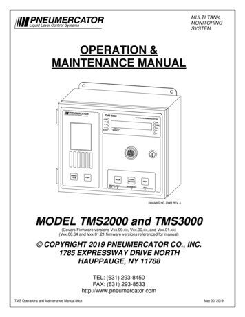
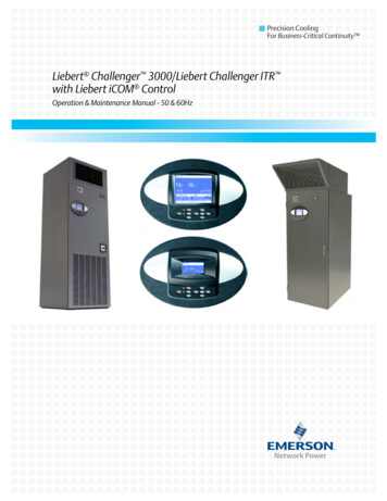
Operation with Liebert iCOM Control3.0OPERATION WITH LIEBERT ICOM CONTROLThe Liebert iCOM control offers the highest capabilities in unit control, communication andmonitoring of Liebert mission-critical cooling units.Liebert iCOM may be used to combine multiple cooling units into a team that operates as a singleentity, enhancing the already-high performance and efficiency of Liebert’s units.3.1FeaturesLarge and Small DisplaysThe Liebert iCOM control is available with either a large or small liquid crystal display. The Liebert iCOM with small display has a 128 x 64 dot matrix screen that shows text andicons. This display is capable of controlling only the unit it is directly connected to. The Liebert iCOM with large display has a 320 x 240 dot matrix screen that shows text andicons of 32 connected units (see Figure 4). This display can be used to control a single cooling unitor any cooling unit within a connected group over a network.Liebert iCOM’s menu-driven display is used for all programming functions. The Status menu showsthe temperature of the return or supply air and the and humidity of the return air.Figure 1Liebert iCOM componentsWall Mount Large DisplayUnit Panel MountSmall Display and BezelUnit Panel Mount Large Displayand BezelLiebert iCOM Input/Output BoardLiebert vNSA Network Switch6
Liebert iCOM Display Components and Functions4.0LIEBERT ICOM DISPLAY COMPONENTS AND FUNCTIONSThe small and the large display
Precision Cooling For Business-Critical Continuity Liebert Challenger 3000/Liebert Challenger ITR with Liebert iCOM Control Operation & Maintenance Manual - 50 & 60Hz