Transcription
18Ultrasonics: A Technique ofMaterial CharacterizationDharmendra Kumar Pandey1 and Shri Pandey21Department2Departmentof Physics, P.P.N. (P.G.) college, Kanpur-208 001, U.P.,of Physics, University of Allahabad, Allahabad- 211 002, U.P.,India1. IntroductionThe material science and characterization is a field concerned with inventing new materialsand improving previously known materials by developing a deeper understanding ofproperties under different physical conditions. The properties of materials depend upontheir composition, structure, synthesis and processing. Many properties of materials dependstrongly on the structure, even if the composition of the material remains same. This is whythe structure-property or microstructure property relationships in materials are extremelyimportant.On the basis of different physical properties, the materials are classified mainly into fivecategories: (a) metals and alloys, (b) semi-metals and semiconductors, (c) ceramics, glassesand glass-ceramics, (d) polymers, and (e) composite materials. Functional classification ofmaterials includes aerospace, biomedical, electronic, energy and environmental, magnetic,and optical (photonic) materials. The structural classification of materials are of two types as(a) crystalline (single crystal and polycrystalline), and (b) amorphous.The selection of a material and the potential to be manufactured economically and safelyinto useful product is a complicated process. It requires the complete knowledge ofconstituent material not only after production but also in processing. Increased competitionand need of higher productivity and better products from material producing industries arecreating more stringent requirements for process and quality control. This demands thecharacterization of materials. The topic material characterization essentially includes theevaluation of elastic behaviour, material microstructure and morphological features,associated mechanical properties etc. The destructive, semi-destructive and non-destructivetesting (DT & NDT) techniques are available for the complete characterization. Thesecharacterization techniques are the basic tool for the quality control and quality assurance ofthe material or component or product.Ultrasonics, which is a sub category of acoustics deals with acoustics beyond the audio limit.The application of ultrasonics falls into two categories as high frequency- low intensity andlow frequency – high intensity. The low intensity application carries the purpose of simplytransmitting energy through the medium in order to obtain the information about themedium or to convey information through the medium. High intensity applicationdeliberately affects the propagation medium or its contents. So, the low intensity and highSource: Acoustic Waves, Book edited by: Don W. Dissanayake,ISBN 978-953-307-111-4, pp. 466, September 2010, Sciyo, Croatia, downloaded from SCIYO.COMwww.intechopen.com
398Acoustic Wavesintensity application of ultrasonic wave belongs in non-destructive and destructivetechniques of characterization respectively.The quantities, ultrasonic velocity and attenuation are the important parameters, which arerequired for the ultrasonic non-destructive technique of material characterization. Theultrasonic velocity is related to the elastic constants and density of material. Hence, it givesthe information about the mechanical, anisotropic and elastic properties of medium throughit passes. It is also important in low temperature physics because it is involved in theevaluation of Debye average velocity and Debye temperature. Ultrasonic velocity innanofluid depends on the concentration of nano-particles of material dispersed in polymermatrix, thus it is not only important at bulk scale but also at nanoscale. When the ultrasonicwave propagates through the medium, its some part of energy is attenuated through thedifferent mechanism like thermal loss, scattering, absorption, electron-phonon interaction,phonon-phonon interaction, and magnon-phonon interaction etc., called as ultrasonicattenuation. The coefficient of ultrasonic attenuation correlates several physical propertieslike elastic constants, guruneisen parameter, thermal conductivity, thermal relaxation time,acoustic coupling constant, thermal energy density, specific heat, particle size, density,Debye average velocity, and concentration etc. Thus, the material can be characterized withthe knowledge of ultrasonic parameters under different physical conditions.Normally, the ultrasonic NDT of material characterization are used for the determination of(a) elastic constants (Shear modulus, Bulk modulus, Young modulus and lame modulus), (b)microstructure (grain size, texture, density etc.), (c) discontinuity (porosity, creep damage,fatigue damage etc.), and mechanical properties (tensile strength, shear strength, hardnessetc.). The new work in this field also provides the characterization of advanced and smartmaterials like GMR etc. Now a day, the synthesis and characterization of nanomaterials andnanofluids are also in touch of ultrasonic NDT&E.In this chapter, ultrasonic material property characterization has been considered. Initially,it covers information about the ultrasonic wave, its mode of propagation and characteristicproperties. After this, a brief study of ultrasonic velocity and attenuation in solid has beendiscussed, which covers the theoretical evaluation and experimental measurements of theseultrasonic parameters. Later on, the characterization of different material (metals, alloys,platinum group metals, nanomaterials, nanofluid, semiconductor etc) has been discussed onthe basis of these ultrasonic quantities and related parameters.2. Ultrasonic waveAs a sub category of acoustics, ultrasonics deals with the acoustics above the human hearingrange (the audio frequency limit) of 20 kHz. Unlike audible sound waves, the ultrasonicwaves are not sensed by human ear due to the limitations on the reception of vibrations ofhigh frequency and energies by the membrane. Ultrasonic wave exhibits all thecharacteristic properties of sound. Ultrasonic vibrations travel in the form of wave, similarto the way light travels. However, unlike light waves, which can travel in vacuum,ultrasonic wave requires elastic medium such as a liquid or a solid. The wavelength of thiswave changes from one medium to another medium due to the elastic properties andinduced particle vibrations in the medium. This wave can be reflected off with very smallsurfaces due to having much shorter wavelength. It is the property that makes ultrasounduseful for the non-destructive characterization/testing of materials. The knowledge ofgeneration/detection of ultrasonic wave and its characteristics is important for its preciseand suitable application.www.intechopen.com
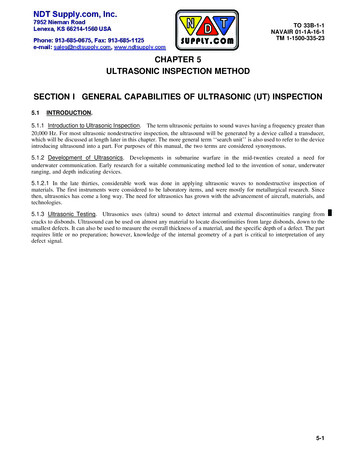
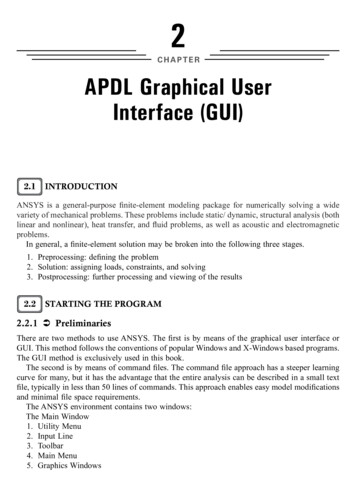
Ultrasonics: A Technique of Material Characterization3992.1 Sources of ultrasonic waveThe ultrasonic wave (UW) can be generated with the mechanical, electrostatic,electrodynamic, electromagnetic, magnetostrictive effect, piezoelectric effect, and lasermethods.Mechanical method or Galton Whistle method is an initial method for the generation ofultrasonic wave. This uses mechanical shock or friction for the generation of wave infrequency range of 100 kHz to 1 MHz. A high frequency of ultrasonic wave (10 to 200 MHz)can be generated using electrostatic method. The magneto inductive effect is used inelectrodynamic method for the production of ultrasound. The mechanical deformation inferromagnetic material in presence of magnetic field is called as magnetostriction. Thisphenomenon is most pronounced in metals such as nickel, iron, cobalt and their alloys.Magnetostriction effect is used for generation of ultrasonic wave in magnetostrictive effectmethod. Most common method for generation of ultrasound is the Piezoelectric effectmethod. In this method, inverse Piezoelectric effect is used for generation of UW. When alaser light incident on the surface of suitable material, its some portion of energy is absorbedat the surface with in the skin depth and rest get reflected. The absorbed energy producestangential stress and then bulk strain through transient surface heating; as a result UW isproduced in concerned medium.2.2 Transducers for ultrasonic waveThe device that converts one form of energy to another form is called as transducer. Anultrasonic transducer converts electrical energy to mechanical energy, in the form of sound,and vice versa. The main components are the active element, backing, and wear plate(Fig.1).Fig. 1. Basic figure of an ultrasonic transducera.The Active ElementThe active element, which is piezo or ferroelectric material, converts electrical energy such asan excitation pulse from a flaw detector into ultrasonic energy. The most commonly usedmaterials are polarized ceramics which can be cut in a variety of manners to produce differentwww.intechopen.com
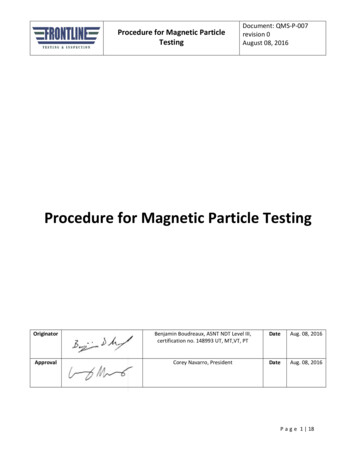
400Acoustic Waveswave modes. New materials such as piezo polymers and composites are also being employedfor applications where they provide benefit to transducer and system performance.b.BackingThe backing is usually a highly attenuative, high density material that is used to control thevibration of the transducer by absorbing the energy radiating from the back face of the activeelement. When the acoustic impedance of the backing matches with the acoustic impedance ofthe active element, the result will be a heavily damped transducer that displays good rangeresolution but may be lower in signal amplitude. If there is a mismatch in acoustic impedancebetween the element and the backing, more sound energy will be reflected forward into thetest material. The end result is a transducer that is lower in resolution due to a longerwaveform duration, but may be higher in signal amplitude or greater in sensitivity.c.Wear PlateThe basic purpose of the transducer wear plate is to protect the transducer element from thetesting environment. In the case of contact transducers, the wear plate must be a durableand corrosion resistant material in order to withstand the wear caused by use on materialssuch as steel. For immersion, angle beam, and delay line transducers, the wear plate has theadditional purpose of serving as an acoustic transformer between the high acousticimpedance of the active element and the water.Now a days, following type of transducers are in use for different applications.1. Normal beam or single element or delay line transducer2. Dual element transducer3. Angle beam transducer4. Immersion transducer5. Mechanical focous transducer6. Electronic time delay focouing or array transducer7. Capacitive transducerIn most of applications piezoelectric transducers are used for generating and receiving theultrasonic waves.2.3 Characteristics of ultrasonic waveFor the appropriate choice of ultrasonic wave with suitable frequency and intensity, theknowledge of some essential parameters related to transducer is important. Thecharacteristic parameters of ultrasonic wave are:1. Sound Field (Near field and far field): The sound field of a transducer is divided in twotwo zones; the near field region or Fresnel zone and far field region or Fraunhofer zone.In the near field region the ultrasonic beam converges and in the far field it diverges.The near field is the region directly in front of transducer where echo amplitudes goesthrough a series of maxima and minima and ends at the last maximum, at the distanceN ( N D 2 / 4C D 2 / 4 ; N: near field distance, D: Element diameter, : frequency, c:material sound velocity, and : wavelength) from the transducer (Fig.2). The intensityvariation along and across the axial distance up to near field region is approximatelyconstant and after which it decreases. The beam boundary defines the limits of thebeam to the point where the disturbance ceases to exist or falls below the thresholdvalue. The beam intensity at the boundary is reduces to one half (6dB) of the intensityat the beam axis (Fig.2).www.intechopen.com
Ultrasonics: A Technique of Material Characterization401(a)(b)IntensityNDistance from the transducer(c)Fig. 2. (a) sound field of transducer, (b) amplitude verses frequency of UW, (c) intensity ofUW verses axial distance from transducer.www.intechopen.com
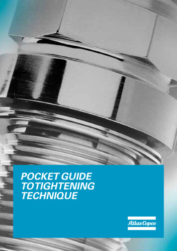
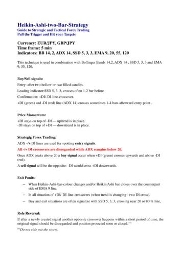
4022.3.Acoustic WavesFocal zone: The starting and ending points of the focal zone on axis of transducer arelocated where pulse echo signal amplitude drops to -6dB of the amplitude at the focalpoint. If ZB and ZE are the beginning and end of the focal zone from the transducer then,then focal zone will be difference of them. The length of focal zone (FZ) is equalto NS F2 [2 /(1 0.5SF )] ; where SF: Normalized focal length F/N, F: focal length, N: nearfield distance.Beam diameter: It is a parameter, which defines the transducers sensitivity. Smaller thebeam diameter, the greater amount of energy is reflected by the flaw. At -6dB drop ofintensity, the beam diameter (BD) at the focus is equal to 0.2568DSF or 1.02FC/ D. Forthe flat transducer, normalized focal length have value one. The Fig.3 represents theclear picture of focal zone and beam diameter.Fig. 3. Focal zone of transducer and beam diameter4.Beam spread or half angle: The spreading of ultrasonic beam always take place as thewave travel from the transducer. In the near field, the beam has a complex shape thatnarrows, while in the far field it diverges. The divergence angle or beam spread angle( θ ) is equal to sin 1 (Kλ / D) or sin 1 (KC /ν D) . Where K is a constant which dependson shape of transducer, edge of beam and method used to determine the beam spread.Itis clear that beam spread from a transducer can be reduced by selecting a transducerwith higher frequency or larger element diameter or both. Fig.4 shows a simplisticunderstanding of beam spread angle.Fig. 4. Ultrasonic beam divergence and angle of divergence2.4 Detection of ultrasonic waveThere are various methods for the detection of UW. The methods are based on the principleof piezoelectric, electrostatic and magnetostriction effects. The classical methods likemechanical and optical methods are also used for the detection of UW. Normally the devicesbased on piezoelectric effect are used commercially for the detection of UW, these devicescomes in electrical method of detection.The prime division of detection in electrical method are the Interferometer or continuouswave (CW) and Pulse technique (PT) methods. In CW method, the UW generated by thewww.intechopen.com
Ultrasonics: A Technique of Material Characterization403source is passed through the concerned medium/specimen, which is reflected from thereflecting plate. The reflecting plate is adjusted towards the source such that the current inthe oscillator of the source changes periodically in maxima or minima. The maximum incurrent corresponds to the half of wavelength interval due to the formation of standingwave between source and plate. This method is preferred in low frequency region for themeasurements of ultrasonic parameters in liquids.The Pulse technique is utilized for detection or measurement of transit time in both liquidsand solids. It uses piezoelectric transducer with and without delay lines for the productionand detection of UW. In this method short duration electric pulses generates the UW withthe broadband piezoelectric transducer. The generated longitudinal or shear wave aretransmitted to the specimen. The reflected wave or echo by the medium are detected by thetransducer on the principle of direct piezoelectric effect and echo pattern is obtained. Usingthis pattern, the exact transit time needed for a signal to travel between the front and backsurface of the specimen or concerned medium is determined, that is used for determinationof ultrasonic velocity and attenuation. The different pulse techniques for precisemeasurements or detection of UW are Sing around, Pulse superposition, Pulse echo overlap,Cross-correlation, Phase slope and Pulse transmission method. Hydrophones are alsopiezoelectric transducer that generates electrical signal when subjected to pressure changeor UW under water. It can detect UW in air, but will be less sensitive due to its design ashaving a good acoustic impedance match with water.3. Material characterization techniques (NDT & DT)The two major classification of material characterization technique are non-destructivetesting (NDT) and destructive testing (DT). Under destructive technique (such as: tensiletesting, creep testing, impact testing, torsion testing, hardness testing etc.) ofcharacterization the tested material or product can not be used again. The destruction of testobject usually makes this type of test more costly. Non-destructive testing technique is aspecific procedure whereby the service ability of materials or components is not impaired bytesting process. The various methods like visual testing, liquid penetrant testing, magneticparticle testing, eddy current testing, radiographic testing, ultrasonic testing, leak testing,thermography and neutron radiography are the NDT technique of material characterization.Among the various non-destructive testing and evalution (NDT&E) plays a key role inmaterial characterization.Ultrasonic properties provide important diagnostic formicrostructural properties as well as deformation processes in a material, controllingmaterial behaviour based on the physical mechanism to predict future performance of thematerials.4. Classification of ultrasonic application and testingThe ultrasonic testing involves both the low intensity and high intensity ultrasonic wave forthe characterization, that belongs in non-destructive and destructive techniques ofcharacterization respectively. Uses of high intensity and low frequency ultrasonic waveincludes medical therapy and surgery, atomization of liquids, machining of materials,cleaning and wielding of plastics and metals, disruption of biological cells, andhomogenization of materials. The low intensity and high frequency ultrasonic waves areapplied for medical diagnosis, acoustical holography, material characterization etc. The lowwww.intechopen.com
404Acoustic Wavesintensity ultrasoud measurements provides a good diagnosis of material property andprocess control in industrial apllication (Alers, 1965; Green,1973; Lowrance, 1975; Renolds,1978; Teagle, 1983; Smith, 1987; Varry, 1987; Thompson,1996; Jayakumar, 1998; Kumar, 2001;Raj, 2003; Roth, 2003; Blodgett, 2005).5. Ultrasonic NDT as a material characterizationThere are four mode of propagation by which an ultrasonic wave can propagate in amedium, as: longitudinal or compressnal wave, transverse or shear wave, surface orRayleigh wave and plate or lamb wave. The most common methods of ultrasonicexamination utilize the longitudinal waves or shear waves.Ultrasonic velocity or attenuation are the parameters that correlate to structuralinhomogenities or flaw size atomistic (interstitials), elastic parameters, precipitates,dislocations, ordering of molecules in liquid crystals, phase transformations, porosity andcracks, concentration of different components of alloys or mixed crystal system, vacancies inlattice sites, size of the nanoparticles in nano-structured materials, electrical resistivity,specific heat, thermal conductivity and other thermophysical properties of the materialsdepending upon the different physical conditions like temperature, pressure,crystallographic orientation, magnetization etc. Thus, ultrasonic study of a materialprovides information about elastic constants, microstructure, discountinuty, and mechanicalproperties under different condition.5.1 Ultrasonic velocityOn the basis of mode of propagation there are four types of ultrasonic velocities, aslongitudinal, shear, surface and lamb wave velocity. Longitudinal and shear wave velocitiesare more important for the material characterization because they are well related to elasticconstants and density. However, it is independent of frequency of wave and dimension ofthe given material. The mechanical behaviour and anisotropic properties of the material canbe well defined on the knowledge of ultrasonic velocity. The mathematical formulationsand measurement techniques for ultrasonic velocity are detailed in following heads.5.1 A Ultrasonic velocity, related parameters and its theoretical evaluationThe mechanical properties of the solids differ from those of fluids in two important respects.Firstly, greater binding forces exist between their constituent atoms so that they supportshear stress. Secondly, anisotropy may occur, especially in single crystal, in which the atomsform regular lattice. The velocity of ultrasonic wave of any kind can be determined from theelastic moduli (Y: Young’s modulus, G: modulus of rigidity, and σ: poisson’s ratio) anddensity (d) of the material. The logngitudinal and shear wave velocities (VL and VS) can bedetermined with following expressions. Y (1 σ )VL d(1 σ )(1 2σ ) 1/2 Yand VS 2 d(1 σ ) 1/2 G d 1/2In terms of lame’s moduli ( and ) , the ultrasonic velocities can be expressed as;www.intechopen.com(1)
405Ultrasonics: A Technique of Material Characterization λ 2μ VL d 1/2 μ and VS d 1/2(2)The stress strain relationships for anisotropic crystals vary with the direction. Thus velocityof ultrasonic wave varies with the direction of propagation of wave and mode ofpolarization. There are three type of ultrasonic velocity (one longitudinal and two shearwave) for each direction of propagation of wave in cubic (Mason, 1958; Singhal 2003) andhexagonal structured materials (Mason,1969; Alers,1958; Rosen,1970; Yadawa,2009). Theexpressions for the velocities are given in Table (1) and Table (2). In Tables 1-2, the V1 islongitudinal and V2 & V3 are the shear wave velocities of ultrasonic wave. The C11, C12, C44,C33 and C66 are the second order elastic constants.The Debye theory of specific heat has proven its usefulness because it is a single –parametertheory which describes the observation remarkebly well. Its one parameter, Debyetemperature (TD) need not to be determined by any heat capacity measurements but can becalculated from the elastic moduli. Once this parameter has been determined from the elasticmoduli, the Debye theory specifies the lattice contribution to the specific heat only to anaccuracy of about 10 or 20% over most of temperature range. Because of this, the theoraticalmodel assumes the solid to be an elastic continuum in which all sound waves travel at thesame velocity independent of their wavelength. This model is satisfactory only in the limit oflong wavelengths or low temperatures. The expression for the TD can be given as:TD VD (6 π 2 n a )1/3KB(3)Here, is quantum of action and is equal to Planck’s constant divided by 2π ; KB isBoltzmann Constant; na is atom concentration. This Debye average velocity is importantDirection ofpropagation100110111Direction ofpolarization100Type r111Long.Any directionin 111 planeShearVelocityexpression(C11 / d )1/2(C 44 / d )1/2(C 44 / d )1/2((C11 C12 2C 44 ) / 2 d )1/2(C 44 / d )1/2((C11 C12 ) / 2 d )1/2((C11 2C12 4C 44 ) / 3d )1/2((C11 C12 C 44 ) / 3d )1/2Table 1. Ultrasonic velocities for cubic structured materialswww.intechopen.comVelocitynotationV1 VLV2 VS1V3 VS2V1 VLV2 VS1V3 VS2V1 VLV2 V3VS1 VS2
406Acoustic WavesDirection ofpropagation001(Alonguniqueaxis or z-axis)100 (or any otherdirectionperpendicular to001)At angle θ withthe unique axis ofthe crystalDirection ofpolarization001TypeofwaveLong.(C33 / d )VelocityexpressionShear(C 44 / d )1/2100Long.(C11 / 2 d )1/2001Shear010ShearLong.V1 VL1/2Anydirection in001 planeV2 V3VS1 VS2V1 VL(C 44 / d )1/2((C11 C12 ) / 2 d )1/2[{C 33Cos 2θ C 11Sin2θ C 44 {[C 11Sin θ C 33Cos θ C 442VelocitynotationV2 VS1V3 VS2V1 VL2(Cos 2θ Sin2θ )]2 4 Cos 2θSin2θ (C 13 C 44 )2 } 1/2 }/2d]1/2Shear[{C 33Cos 2θ C 11Sin2θ C 44 {[C 11Sin2θ C 33Cos 2θ C 44V2 VS1(Cos 2θ Sin2θ )]2 4 Cos 2θSin2θ (C 13 C 44 )2 } 1/2 }/2d]1/2Shear[{C 44Cos 2θ C 66Sin2θ } / d]1/2V3 VS2Table 2. Ultrasonic velocities for hexagonal structured materialsparameter in the low temperature physics because it is related to elastic constants throughultrasonic velocities. The Debye average velocity (VD) in the materials is calculated using thefollowing equation (Oligschleger, 1996). 1 3 1 dΩ VD 3 3 i 1 Vi 4π -1/3(4)Here the integration is over all directions and summation is over the type of ultrasonicvelocities. Along the [100], [111] (for cubic crystal) and [001] (for hexagonal structuredcrystals) direction of propagation of wave, the equation (4) reduces as: 1 12VD 3 3 3 V1 V2 -1/3(4a)and along the [110] (for cubic) and any angle with the unique axis of hexagonal structuredcrystal, direction of propagation, the equation (4) reduces as:www.intechopen.com
407Ultrasonics: A Technique of Material Characterization 1 111 VD 3 3 3 3 V1 V2 V3 -1/3(4b)On the knowlewdge of elastic constants, the theoretical evaluation of ultrasonic velocity andDebye average velocity in cubic and hexagonal structured materials can be done with help ofexpressions written in Table (1), Table (2) and equations (4a)-(4b). There are several theories(Ghate,1965; Mori,1978; Rao,1974; Yadav AK, 2008) for the calculation of elastic constants. Theelastic constants depend on the lattice parameters of structured materials. The elastic constantsand elastic moduli can be calculated with the knowledge of lattice parameters.5.1 B Measurement techniques of ultrasonic velocityThe study of the propagation of ultrasonic waves in materials determines the elasticconstants, which provides better understanding of the behaviour of the engineeringmaterials. The elastic constants of material are related with the fundamental solid statephenomenon such as specific heat, Debye temperature and Grüneisen parameters. Theelastic constants in the materials can be determined by measuring the velocity oflongitudinal and shear waves. Elastic constants are related to interatomic forces, coordination changes etc., and also with the impact shock, fracture, porosity, crystal growthand microstructural factors (grain shape, grain boundaries, texture and precipitates etc.). So,the study of ultrasonic velocity is useful not only for characterization of the structuredmaterials, engineering materials, porous materials, composites, glasses, glass ceramics butalso bioactive glasses, nanomaterials, nanofluids etc.Interferometer or continuous wave method and pulse technique are the general electricalmethod for the measurement of ultrasonic velocity. In CW method, the wavelength of wavein the test material is measured, which in turn provides the ultrasonic velocity withrelation V ν λ . While in the Pulse technique, transit time (t: the time needed for a signal totravel between the front and back surface of the specimen or concerned medium) ismeasured with the help of echo pattern. If x is thickness of the material then ultrasonicvelocity becomes equal to 2x/t.For precise measurement, the Pulse technique has been improved in the form of followingtechniques (Papadakis, 1976, Raj, 2004).a. Sing aroundb. Pulse superposition methodc. Pulse echo overlap methodd. Cross-correlation method ande. Phase slop methodf. Pulse transmission methodThe pulse echo-overlap, pulse transmission and pulse superposition techniques are widelyused techniques due to their absolute accuracy and precision respectively. Now a day,computer controlled devices of pulse echo overlap and pulse superposition techniques arebeing used. Resonance ultrasound spectroscopy and Laser interferometry are the recenttechniques for the measurement of ultrasonic velocity in thin film, crystal, textured alloy etc.5.1 C Application of ultrasonic velocityUltrasonic velocity has a wide range of application in the field of material characterization.Yet it is useful for the characterization or study of all the three phase of matter but here wewww.intechopen.com
408Acoustic Wavesconcentrate only its application to solid materials. It is used in the study of followingproperties of materials.1. Elastic constants: The elastic moduli of a material are important for the understanding ofmechanical behaviour. If VL and VS are the measured ultrasonic velocities of longitudinaland shear wave then longitudinal modulus (L), Shear modulus (G), Bulk modulus (B),Poisson’s ratio (σ),Young modulus (Y) and lame’s modulus ( and ) can be obtained withthe following expression. L VL2 dμ GB L (4 / 3)GL 2Gσ 2(L G )Y (1 σ )2G VS2 dλ (VL2 2V S2 )d(5)We can also find the stiffness constants or second and forth order elastic constants with thevelocity. Using Table (1)-(2), one can find the second order elastic constants along differentcrystallographic direction for cubic and hexagonal structured materials. If we haveultrasonic velocity under different physical condition like temperature, pressure,composition of materials etc. then we can predict the mechanical behaviour of material indifferent physical condition. The anisotropy of material can be explained with theknowledge of anisotropy factor A [2C44/(C11-C12)]. Knowledge of pressure derivatives ofthe elastic constants of a structured material can be used for the evaluation of Grüneisenparameter ( γ ). The Grüneisen parameter is used to describe anharmonic properties ofsolids. The quasi harmonic model is usually the starting point for the evaluation of modegammas γ i which is defined as γ i [ d (ln ωi ) / d (ln V )] , where ωi is a normal modefrequency of crystal lattice and V is the volume of the crystal. The values of γ i for lowfrequency acoustic modes in a given material can be obtained with the pressure derivates ofelastic constants of that material. Finally the Grüneisen parameter is obtained with theaverage of γ i a
18 Ultrasonics: A Technique of Material Characterization Dharmendra Kumar Pandey 1 and Shri Pandey 2 1Department of Physics, P.P.N. (P.G.) college, Kanpur-208 001, U.P., 2Department of Physics, University of A llahabad, Allahabad- 211 002, U.P., India 1. Introduction The material science and character