Transcription
Aerospace Sheetmetal DesignVersion 5 Release 14Aerospace Sheetmetal DesignOverviewConventionsWhat's New?Getting StartedEntering the Aerospace SheetMetal Design WorkbenchDefining the Aerospace SheetMetal ParametersCreating a Web from a SketchCreating a Surfacic Flange on a WebCreating a Cutout with a SketchExtracting Drawings from the Aerospace SheetMetal Design PartUser TasksManaging the Default ParametersEditing the Sheet and Tool ParametersComputing the Bend AllowanceDefining the CompensationsCreating a WebCreating a Surfacic FlangeCreating a JoggleCreating Swept WallsCreating a FlangeCreating a HemCreating a Tear DropCreating a User FlangeUnfoldingFolded/Unfolded View AccessConcurrent AccessCreating a CutOutCreating a HoleCreating Stamping FeaturesCreating a Flanged HoleCreating a BeadCreating a Circular StampCreating a Surface StampCreating a Flanged CutoutCreating a Stiffening RibCreating a Curve StampCreating User-Defined Stamping FeaturesCreating a Punch with a DieCreating a Punch with Opening FacesPage 1
Aerospace Sheetmetal DesignVersion 5 Release 14Editing User-Defined StampsCreating a Local Corner ReliefCreating ConstraintsMapping ElementsCreating CornersCreating ChamfersPatterningCreating Rectangular PatternsCreating Circular PatternsCreating User-Defined PatternsReference ElementsCreating PointsCreating LinesCreating PlanesDisplaying Characteristic CurvesLooking For Aerospace SheetMetal FeaturesBrowsing the Sheetmetal CatalogIntegration With Part DesignWorkbench DescriptionMenu BarAerospace SheetMetal ToolbarStampings ToolbarConstraints ToolbarReference Elements ToolbarSpecification TreeCustomizingAerospace Sheet Metal DesignCustomizing Standards Files to Define Design TablesCustomizing Standards Files to Define Methods for CompensationsGlossaryIndexPage 2
Version 5 Release 14Aerospace Sheetmetal DesignPage 3OverviewWelcome to the Aerospace SheetMetal Design User's Guide. This guide is intended for users who need tobecome quickly familiar with the Aerospace SheetMetal Design Version 5 product.This overview provides the following information: Aerospace SheetMetal Design in a Nutshell Before Reading this Guide Getting the Most Out of this Guide Accessing Sample Documents Conventions Used in this GuideAerospace SheetMetal Design in a NutshellThe Aerospace Sheetmetal Design workbench provides an associative feature-based modeling, making itpossible to design sheetmetal parts in concurrent engineering between an unfolded or folded partrepresentation.Aerospace Sheetmetal allows you to define a part using predefined features. Both folded geometry andflattened geometry can be computed from the feature specifications.The Aerospace SheetMetal Design User's Guide has been designed to show you how to design aerospace sheetmetal parts of varying levels of complexity.Before Reading this GuideBefore reading this guide, you should be familiar with basic Version 5 concepts such as documentwindows, standard and view toolbars. Therefore, we recommend that you read the Infrastructure User'sGuide that describes generic capabilities common to all Version 5 products. It also describes the generallayout of V5 and the interoperability between workbenches.You may also like to read the following complementary product guides, for which the appropriate license isrequired: Part Design User's Guide: explains how to design precise 3D mechanical parts. Generative Drafting User's Guide: explains how to generate drawings from 3D parts and assemblydefinitions.
Aerospace Sheetmetal DesignVersion 5 Release 14Page 4Getting the Most out of This GuideTo get the most out of this guide, we suggest that you start reading and performing the step-by-stepGetting Started tutorial.Once you have finished, you should move on to the next sections, which explain how to handle moredetailed capabilities of the product.The Workbench Description section, which describes the Aerospace SheetMetal Design workbench will alsocertainly prove useful.Accessing Sample DocumentsTo perform the scenarios, you will be using sample documents contained in the online\aslug\samplesfolder. When samples belong to capabilities common to different SheetMetal products, those samples willbe found in the online\cfysa\samples\SheetMetal folder. For more information about this, refer toAccessing Sample Documents in the Infrastructure User's Guide.
Version 5 Release 14Aerospace Sheetmetal DesignConventionsCertain conventions are used in CATIA, ENOVIA & DELMIA documentation to help you recognize andunderstand important concepts and specifications.Graphic ConventionsThe three categories of graphic conventions used are as follows: Graphic conventions structuring the tasks Graphic conventions indicating the configuration required Graphic conventions used in the table of contentsGraphic Conventions Structuring the TasksGraphic conventions structuring the tasks are denoted as follows:This icon.Identifies.estimated time to accomplish a taska target of a taskthe prerequisitesthe start of the scenarioa tipa warninginformationbasic conceptsmethodologyreference informationinformation regarding settings, customization, etc.the end of a taskPage 5
Aerospace Sheetmetal DesignVersion 5 Release 14functionalities that are new or enhanced with this releaseallows you to switch back to the full-window viewing modeGraphic Conventions Indicating the Configuration RequiredGraphic conventions indicating the configuration required are denoted as follows:This icon.Indicates functions that are.specific to the P1 configurationspecific to the P2 configurationspecific to the P3 configurationGraphic Conventions Used in the Table of ContentsGraphic conventions used in the table of contents are denoted as follows:This icon.Gives access to.Site MapSplit View modeWhat's New?OverviewGetting StartedBasic TasksUser Tasks or the Advanced TasksWorkbench Page 6
Aerospace Sheetmetal DesignVersion 5 Release 14Page 7IndexText ConventionsThe following text conventions are used: The titles of CATIA, ENOVIA and DELMIA documents appear in this manner throughout the text. File - New identifies the commands to be used. Enhancements are identified by a blue-colored background on the text.How to Use the MouseThe use of the mouse differs according to the type of action you need to perform.Use thismouse button. Whenever you read. Select (menus, commands, geometry in graphics area, .)Click (icons, dialog box buttons, tabs, selection of a location in the document window,.) Double-click Shift-click Ctrl-click Check (check boxes) Drag Drag and drop (icons onto objects, objects onto objects) Drag Move Right-click (to select contextual menu)
Version 5 Release 14Aerospace Sheetmetal DesignPage 8What's New?New FunctionalitiesHybrid DesignYou can now create wireframe and surfacic features within the same solid body which impacts thebehavior of webs, surfacic flanges and corner reliefs.User-stampYou can now create user-stamps.Enhanced FunctionalitiesJoggle on WebYou can now create joggles on a web.Runout parametersYou can now define precisely the runout parameters of the joggles.CutoutsAdditional possibilities are now available when creating a cutout: you can choose a direction for thecutout that is different from, or equal to, the normal direction. Additionally, the extrusion can now be oflesser length than the thickness. You can also now specify several supports for the cutout, instead ofjust one previously.Flange patternYou can now create a pattern from a flange on rectangular, circular or user-defined patterns.Document chooser integration.You can now customize the document environment (Tools/Options/General/Document tab) in order toselect documents or paths using various interfaces (folder, Enovia, and so on). The interface can becustomized for a folder or DLName path selection interface.
Version 5 Release 14Aerospace Sheetmetal DesignPage 9Getting StartedBefore getting into the detailed instructions for using Version 5 CATIA - Aerospace Sheet Metal Design, thefollowing tutorial provides a step-by-step scenario demonstrating how to use key functionalities.The main tasks proposed in this section are:Entering the Aerospace SheetMetal Design WorkbenchDefining the Aerospace SheetMetal ParametersCreating a Web from a SketchCreating a Surfacic Flange on a WebCreating a CutoutExtracting Drawings from the Aerospace SheetMetal Design PartAll together, these tasks should take about 20 minutes to complete.
Aerospace Sheetmetal DesignVersion 5 Release 14Page 10Entering the Aerospace SheetMetal DesignWorkbenchThe Aerospace Sheet Metal Design functions are available when you are in the Part environment. Severalfunctions are integrated from the Part Design workbench.This task shows how to enter the workbench.Choose the Mechanical Design - Aerospace Sheet Metal Design item from the Start menu.The Aerospace Sheet Metal toolbar is displayed and ready to use.
Aerospace Sheetmetal DesignVersion 5 Release 14Page 11You may add the Aerospace Sheet Metal Design workbench to your Favorites, using the Tools - Customize item. For more information, refer to the Infrastructure User's Guide.If you wish to use the whole screen space for the geometry, remove the specification tree clicking off theView - Specifications menu item or pressing F3.
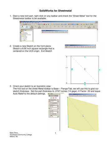
Aerospace Sheetmetal DesignVersion 5 Release 14Page 12Defining the Aerospace SheetMetal ParametersThis task shows you how to configure the Aerospace SheetMetal parameters.1. Click the Sheet Metal Parameters icon.The Sheet Metal Parameters dialog box is displayed.2. Change the Thickness if needed.3. Change the Minimum Bend Radius if needed. The Minimum Bend radius defines the minimuminternal radius allowing the creation of a bend.4. Click OK to validate the parameters and close the dialog box. The Sheet Metal Parametersfeature is added in the specification tree.The other two tabs are not used in this scenario.
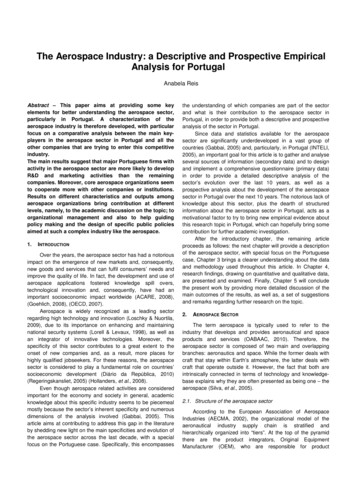
Version 5 Release 14Aerospace Sheetmetal DesignPage 13Creating a Web from a SketchThis section explains how to create a web.The web is the main feature of an Aerospace Sheetmetal Design part: there is always one (and onlyone) web.1. Click the Sketcher icon.2. Select the xy plane.3. Click the Rectangle iconin the Profile toolbar to create the profile of the web.4. Click to create the first point and drag the cursor.5. Click to create the second point: the rectangle profile is displayed.6. Click the Exit workbench7. Click the Web iconto return to the 3D world.The Web definition dialog box is displayed.
Aerospace Sheetmetal DesignVersion 5 Release 148. Select the sketch you just created as the support of the web.A preview of the web appears.9. Click OK to create the web.Here is the web.Page 14
Aerospace Sheetmetal DesignYou can click the Sketcher iconVersion 5 Release 14to edit the sketch.Page 15
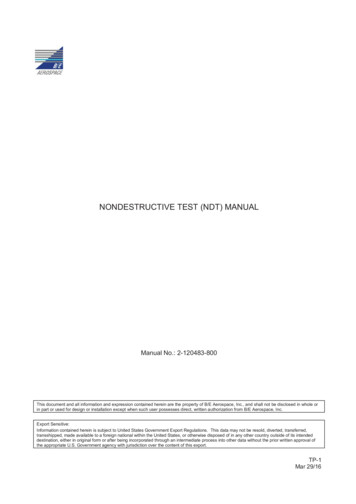
Aerospace Sheetmetal DesignVersion 5 Release 14Page 16Creating a Surfacic Flange on a WebThis section explains how to create a surfacic flange on a web, that is a feature which enables to stiffenthe part.The web is still open from the previous task.1. Click the Surfacic flange icon.The Surfacic Flange definition dialog box is displayed.2. Choose the web as the Base Feature.3. Choose the yz plane as support.
Aerospace Sheetmetal DesignVersion 5 Release 144. Click Preview to see the surfacic flange.5. Click OK to create the surfacic flange.Here is the surfacic flange.Page 17
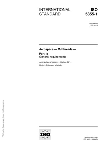
Version 5 Release 14Aerospace Sheetmetal DesignPage 18Creating a Cutout with a SketchIn this task, you will learn how to: open a sketch on an existing face define a profile on the face in order to create a cutout.You can create a cutout defined either by a sketch or an open geometry.The surfacic flange is still open from the previous task.1. Select the surface from the geometry area to define the working plane.2. Click the Sketcher icon.3. Click the Elongated Hole iconto create the contour.To access the oblong profile, click the black triangle on the Rectangle icon. It displays a secondarytoolbar.4. Click to create the first point and drag the cursor.5. Click to create the second point. The first semi-axis of the profile is created.6. Drag the cursor and click to create the third point. The second semi-axis is created and theoblong profile is displayed.
Version 5 Release 14Aerospace Sheetmetal Design7. Click the CutOut icon7. Select the sketch.Page 19
Aerospace Sheetmetal DesignVersion 5 Release 14Page 20The CutOut Definition dialog box is displayed and a cutout is previewed with default parameters.The vectors show the side and the direction of the cutout.8. Select the Dimension type to define the limit of your cutout.9. Click OK. Here is your cutout.
Version 5 Release 14Aerospace Sheetmetal DesignExtracting Drawings from theAerospace SheetMetal Design PartThis task shows how to create the Aerospace SheetMetal Design Part views in the Generative Drafting workbench.The Sheet Metal part is displayed.1. Clickor select File - New.2. Select the Drawing type and click OK.The Generative Drafting workbench is launched.The New Drawing dialog box opens.3. Click OK.For more information about this workbench, refer to Generative Drafting User's Guide.4. The drawing sheet appears.5. Tile the windows horizontally using the Window - Tile Horizontally menu item.6. Select the Unfolded View iconin the Projections toolbar from Generative Drafting Workbench.Page 21
Aerospace Sheetmetal DesignVersion 5 Release 14This icon is added to the Projections toolbar provided the Sheet Metal workbench is present.7. Choose the xy plane in the Sheet Metal specification tree.The unfolded view is displayed with the bends axes and limits.Eventually, the Drafting sheet looks like this:Page 22
Aerospace Sheetmetal DesignVersion 5 Release 14User TasksManaging the Default ParametersCreating a WebCreating a Surfacic FlangeCreating a JoggleCreating Swept WallsUnfoldingCreating a CutOutCreating a HoleCreating Stamping FeaturesCreating User-Defined Stamping FeaturesCreating a Local Corner ReliefCreating ConstraintsMapping ElementsCreating CornersCreating ChamfersPatterningReference ElementsDisplaying Characteristic CurvesLooking For Aerospace SheetMetal FeaturesBrowsing the Sheetmetal CatalogIntegration With Part DesignPage 23
Aerospace Sheetmetal DesignVersion 5 Release 14Page 24Managing the Default ParametersThis section explains and illustrates how to use or modify various kinds of features.The table below lists the information you will find.Using Aerospace Sheetmetal Design assumes that you are in a CATPart document.Edit the parameters: select the Parameters tab and define the element thickness and bend radiusvalues.Compute the bend allowance: select the Bend Allowance tab and define the allowance value (K factor).Define the compensations and runout: select the Joggles tab and define the compensations and therunout for the joggle.Please refer to the Customizing chapter to define the Sheet Standards Files.
Version 5 Release 14Aerospace Sheetmetal DesignPage 25Editing the Sheet and Tool ParametersThis section explains how to change the different sheet metal parameters needed to create your first feature.1. Click the Sheet Metal Parameters icon.The Sheet Metal Parameters dialog box is displayed.2. Change the Thickness if needed.3. Change the Minimum Bend Radius if needed.The Minimum Bend radius defines the minimum internal radius allowing the creation of a bend.4. Change the Default Bend Radius if needed. To do this, you need to deactivate the formula first by right clicking the formula icon.The Default Bend Radius corresponds to the internal radius and is linked by default to the creation of the surfacic flanges.You can set the value to 0 to create bend with no radius. If using the DIN standard, the KFactor automatically sets to 0 as well.Convention dictates that the inner angle between the two elements is used to define the bend.It can vary from 0deg to 180deg exclusive. This angle is constant and the bend axis is rectilinear.5. Click OK to validate the Sheet Metal Parameters.The Standard field displays the Standard to use with the part, if implemented. The name of this standard file is defined in a Design Table.Parameters can be defined in a Design Table. To do so, press the Sheet Standards Files. button to access the company defined standards, if need be. For more information, refer to the Customizing Standard Files section.To know more about the different ways to access you files, refer to the Opening Existing Documents Using the Browse Window section.All parameters hereafter, or only some of them, can be defined in this Design Table:
Sheet Metal Parameters Standard in Sheet Metal ParametersPage 26Version 5 Release 14Aerospace Sheetmetal DesignColumn associated in the Design Table SheetMetalStandardDefinition sheet reference name Thickness Thickness sheet thickness Minimum Bend Radius MinimumBendRadius minimum bend radius Default Bend Radius DefaultBendRadius default bend radius K Factor KFactor neutral fiber position Radius Table RadiusTable path to the file with all available radiiIn all cases, the Thickness parameter must be defined in the Design Table in order for the other parameters to be taken into account.Standard Names For Holes Clearance HoleColumn associated in the Design Table ClearanceHoleStdDefinition path to the Clearance Hole Standard file Index Hole IndexHoleStd path to the Index Hole Standard file Manufacturing Hole ManufacturingHoleStd path to the Manufacturing Hole Standard file Fastener Hole FastenerHoleStd path to the Fastener Hole Standard fileStandard Names For Stamps Flanged HoleColumn associated in the Design Table ExtrudedHoleStdDefinition path to the Flanged Hole Standard file Bead BeadStd path to the Bead Standard file Circular Stamp CircularStampStd path to the Circular Stamp Standard file Surface Stamp SurfaceStampStd path to the Surface Stamp Standard file Flanged CutOut FlangedCutoutStd path to the Flanged CutOut Standard file Curve Stamp CurveStampStd path to the Curve Stamp Standard file Stiffening RibWhen a parameter refers to a path, another sub-Design Table will be associated to the corresponding feature.Example for a hole standard file:Main Sheet Metal Parameters Design TableHole StandardWhenever a hole is created, a design table will associate its radius with a standard name.Example for a stamp standard file:Main Sheet Metal Parameters Design TableWhenever a stamp is created, a design table will associate its dimension with a standard name.
Aerospace Sheetmetal DesignSurface StampCurve StampCircular StampBeadFlanged CutoutFlanged HoleStiffening RibVersion 5 Release 14Page 27
Aerospace Sheetmetal DesignVersion 5 Release 14Page 28Computing the Bend AllowanceThis section explains the calculations related to folding/unfolding operations.1. Click the SheetMetal Parameters icon.The Sheet Metal Parameters dialog box isdisplayed.The fourth tab concerns the bend allowance.Bend AllowanceThe bend allowance corresponds to the unfolded bend width.bend 90degbend 90degL is the total unfolded lengthA and B the dimensioning lengths as defined on the above figure. They are similar to the DINdefinition. K FactorPhysically, the neutral fiber represents the limit between the material compressed area inside the bendand the extended area outside the bend. Ideally, it is represented by an arc located inside the thicknessand centered on the bend axis.
Aerospace Sheetmetal DesignVersion 5 Release 14Page 29The K factor defines the neutral fiber position:W α * (R k * T)where:W is the bend allowanceR the inner bend radiusT the sheet metal thicknessα the inner bend angle in radians.If β is the opening bend angle in degrees:α π * (180 - β) / 180When you define the sheet metal parameters, a literal feature defines the default K Factor and a formulais applied to implement the DIN standard. This standard is defined for thin steel parts. Therefore the KFactor value ranges between 0 and 0.5.The DIN definition for the K factor slightly differs.W α * (R k' * T/2)Therefore k' 2 * k and ranges from 0 to 1.This formula can be deactivated or modified by right-clicking in the K factor field and choosing an optionfrom the contextual menu. It can be re-activated by clicking the Apply DIN button. Moreover, the limitvalues can also be modified.When a bend is created, its own K Factor literal is created.Two cases may then occur:a. If the Sheet Metal K Factor has an activated formula using the default bend radius as inputparameter, the same formula is activated on the bend K Factor replacing the default bend radiusby the local bend radius as input.b. In all other cases, a formula "equal to the Sheet Metal K Factor" is activated on the local bend KFactor.This formula can also be deactivated or modified.Bend DeductionWhen the bend is unfolded, the sheet metal deformation is thus represented by the bend deduction V,defined by the formula:L A B V(refer to the previous definitions).Therefore the bend deduction is related to the K factor using the following formula:V α * (R k * T) - 2 * (R T) * tan ( min(π/2,α) / 2)
Aerospace Sheetmetal DesignVersion 5 Release 14Page 30This formula is used by default. However, it is possible to define bend tables on the sheet metalparameters. These tables define samples: thickness, bend radius, open angle, and bend deduction. Inthis case, the bend deduction is located in the appropriate bend table, matching thickness, bend radius,and open angle. If no accurate open angle is found, an interpolation will be performed.When updating the bend, the bend deduction is first computed using the previously defined rules. Thenthe bend allowance is deduced using the following formula:W V 2 * (R T) * tan ( min(π/2,α) / 2)When the bend deduction is read in the bend table, the K factor is not used.
Aerospace Sheetmetal DesignVersion 5 Release 14Page 31Defining the Compensations and RunoutThis section shows how to select the appropriate method to define compensations when flattening asurfacic flange or a surfacic flange with a joggle.Compensation is a modification of the standard calculation of the unfolding process which intends to bestrepresent the material behavior.You first need to define which method you want to apply by customizing design tables. To do so, proceedas explained in Customizing Standards Files To Define Methods for Compensations.1. Click the SheetMetal Parameters icondisplayed. The Sheet Metal Parameters dialog box is
Aerospace Sheetmetal DesignVersion 5 Release 14Page 322. Click the Joggles tab.3. In the Compensations combo list, select the method as defined in the SheetMetalStandard files: None: no compensation is applied Method 1 ( Method V4) Method 2If the method you chose is not the one defined in the SheetMetal Standard Files, a warning message isissued prompting you to select another method or the corresponding file.You can click the information icon to display a schema explaining both methods. More information isavailable in Customizing Standards Files To Define Methods for Compensations.4. In the Definition combo list, select the runout definition: External: this type of runout includes the Joggle fillets. Internal: this type of runout excludes partially the Joggle fillets.You can click the information icon to display a schema explaining both types of runout.
Aerospace Sheetmetal DesignVersion 5 Release 14Page 335. In the Runout section, modify the formula's coefficient by clicking the up and down arrows.The Runout formula corresponds to the coefficient multiplied by the depth.If you create a new part, you can modify the formula's coefficient.If you work on a part created in a previous version, when you create a joggle a warning is displayedasking you to validate this parameter in the Sheetmetal Parameters dialog box.6. Click OK in the dialog box to validate the compensations and runout parameters.
Aerospace Sheetmetal DesignVersion 5 Release 14Creating a WebThis section explains how to create a web, that is the main feature of an Aerospace SheetMetal Design part.Open the Web1.CATPart document.1. Click the Web icon.The Web definition dialog box is displayed.2. In the Support field, select the support geometry in the specification tree. It can either be: a plane (example from the Web from open geometry geometrical set).The Material Direction is displayed, perpendicular to the geometrical support. You can reverse the direction by clicking the arrow. a closed sketch (example from the Web from closed sketches geometrical set).In our example, there are two closed sketches: the web will be calculated on the smallest part of the second sketch.The Material Direction is displayed, perpendicular to the geometrical support. You can reverse the direction by clicking the arrow.Page 34
Aerospace Sheetmetal DesignVersion 5 Release 14You can click the Invert Material Dir button to reverse the material direction of the web.3. In the Boundary field, in the case of an open geometry, select the elements that limit the support geometry. It can either be: a list of elements (curves, surfaces, or planes) one or more sketchesThe elements must be selected consecutively.They are displayed in the Boundary frame, in the order you have just chosen them, as well as in the 3D geometry.Page 35
Aerospace Sheetmetal DesignVersion 5 Release 14When a closed profile can be built, a light preview of the web is available. Otherwise, click Preview.You can modify the selection by selecting an existing limit and using the following buttons to: add a limit after the selected limit (Add After) add a limit before the selected limit (Add Before) replace a limit (Replace) remove a limit (Remove) select a limit more than one time (Insert)In the following example, we first select three elements to limit the web.Page 36
Aerospace Sheetmetal DesignPage 37Version 5 Release 14Then we select Surface.1 and click on the pink sketch to add it to the web's definition.Then we select Surface.1 again and click on the yellow sketch to add it to the web's definition.Note that Surface.1 is displayed twice in the WebDefinition dialog box.The Web is created according to several elements. select several limits to modify the existing limit (Multiple Sel). This option is available once you have selected Add After: the Limits to Adddialog box appears to let you select the limits. remove all limits (Remove All)Once you have modified the selection, a light preview is available. You can click the Preview button to display the result of the web.When the profile is defined by a list of geometrical elements, the following operations are performed: the curves are projected on the web geometrical support the surfaces are intersected with the web geometrical support4. Click OK.The web (identified as Web.1) is created and the specification tree is updated accordingly.
Aerospace Sheetmetal DesignPage 38Version 5 Release 14Features are displayed when editing Web.1's panel.The sketches are aggregated under the web (identified as Web.xxx). Sketch.1 is displayed in No Show mode as it was only used to create the web.In hybrid context, even though a web is created with several features, none are aggregated under the web in the specification tree.Specification tree's behavior in hybrid context.Specification tree's behavior in pre-hybrid context.Yet, if you open a part created in a previous release, the specification tree will be displayed accordingly to the previous behavior.Fore more information about Hybrid Design, refer to the Hybrid Design section.
Version 5 Release 14Aerospace Sheetmetal DesignPage 39Creating a Surfacic FlangeThis section explains how to create a surfacic flange on a web, or an existing surfacic flange (in that case, theirfillets must not intersect).Understanding the surfacic flangeWhen creating a surfacic flange, the bend is propagated along the whole base feature (with a continuity intangency).In certain cases this propagation prevents the surfacic flange from being relimited: it happens when the selectededge allows propagation of the bend.Open the SurfacicFlange1.CATPart document. Create a web as shown in the previous task.Here are the different elements taken into account when creating a surfacic flange: Base Feature Support EOP Sides and Corners Process Compensations1. Click the Surfacic Flange icon.The Surfacic Flange definition dialog box is displayed.
Aerospace Sheetmetal DesignPage 40Version 5 Release 14Base FeatureIn the Base Feature tab, the Bend Radius is of Constant type. It is set to the default bend radius of thepart.2. You can modify the fillet Radius value by changing the driving equation: click theicon.The Formula Editor dialog box opens, you can modify the dictionary and the parameters.Or you may need to deactivate the formula using the contextual menu on the field and choosing Formula Deactivate before editing the value.3. Choose the web as the Base Feature.Once you chose the base feature, the Support tab automatically displays.Support4. In the Support tab, choose the surfacic flange's geometrical support. It can either be a surface, a plane or acurve.Make sure the support is big enough to be able to later define an EOP with a length from OML.The OML is a curve created by intersecting the flange support and a plane perpendicular to the web and normal tothe OML.
Aerospace Sheetmetal Design Version 5 Release 14Page 41Exact: the selected support is to be used for the creation of the surfacic flange.Approximation: the support surface is approximated using a ruled surface. This ruled surface is defined fromtwo curves: the OML (in light blue), computed at the intersection between the support surface and the web plane. a curve parallel to the OML (in pink), computed at a distance equal to the approximation lengthThis mode enab
Creating a Web from a Sketch This section explains how to create a web. The web is the main feature of an Aerospace Sheetmetal Design part: there is always one (and only one) web. 1. Click the Sketcher icon . 2. Select the xy plane. 3. Click the Rectangle icon in the Profile toolbar to create the profile of the web. 4.