Transcription
Three Dimensional (3D)Having the dimensions of height, width, and depth.Thumbnail SketchA preliminary visual of a possible idea for a design. Most thumbnail sketches are not fuji-size and havelittle detail. They are intended to quickly explore possible alternative designs.Two Dimensional (2D)Having the dimensions of height and width, height and depth, or width and depth only.Two-Point PerspectiveA realistic way of drawing objects in three dimensions using a horizon line, a key edge, and twovanishing points.Vanishing PointA point in space, usually located on the horizon, where parallel edges of an object appear to converge.ViewsViews is shorthand for multiview projection, which is a system used to view an object. The six mutuallyperpendicular directions any object may be viewed are top, front, right-side, rear, left-side, and bottom.Top, front, and right-side views are also referred to as the three regular views because they are thethree views most frequently used.VisualizeTo imagine the visual form of an object or situation that one cannot see.
WidthThe measurement or extent of something from side to side.
-o 0’020LiUI—Li-JI—C-,C-,C-)Li-oCC’)00 CDci)000)-c0CD0I.C-,I’a)-CoC-).-ci)Cp
Cl)a)I.a)-(I-I-.’-o-oC( )a)C.)a)11Cl)C(C) 1a)C-o0Cl)Cl).EEt0CCI)0—oil.
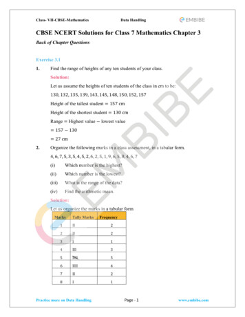
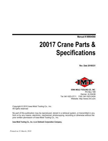
Width and depthlines are drawn at300 from thehorizon line. One view showsheight, width, anddepth.;———-.I1F Iii1111111—-11 1N-----—L‘:.— —-——p.7.L111--LLJ—-—r——ITÔPW1iNUTJ L.1--I-—*-.L:.J 1 LLi 1-.--.—----.-ZZZEE-‘-IL JL--i---:::::::izi::JL[O LS,—Isometric Sketch
Isometric Grid Paper3D S ketching Techniques
ICopy andlabel thiscube onyourisometricaxis.HIGWi04/7%IsoMr’c CUBEThumbnail Isometric Sketch
Additive andSubtractive 3Dsketch Follow the steps inyour activity tocomplete thisdrawing on theisometric graphpaper.Isometric Thumbnail Sketch
Perspective is a way todraw that shows a viewof the object in the mostrealistic way. Vanishing points areused to guide the linesin the object to thehorizon line or thehorizontal line you seeat your line of sight.Perspective—4-—
All lines in the depthproject to one point (thevanishing point). The location of thevanishing point is basedon your line of sight. Copy this one-pointperspective sketch ontoyour activity. Label thefront, top, and right side.FrontVanishing Point (VP)One-Point Perspective
-4-VP2 In two-point perspective, the width linesconverge on one vanishing point (VPI),and the depth lines converge on the othervanishing point (VP2). Copy this two-point perspective onto youractivity sheet. Label the top, front, andside.VPITwo-Point Perspective
7III1:IIIILiii-I -r0c.,22LAc3)CUI
An orthographic sketchis used to show truesize and shape. Each view is adjacent tothe other as if unfoldedfrom a 3D shape. Notice the top view isdirectly above the frontwith the right side viewdirectly to the right ofthe front.IFront-———1TopIISiIeOrthographic (Multiview) Sketching
Copy thisorthographicsketch onto youractivity sheet.Label the top,front, and rightside. Don’t forget thehidden lines.-- - —r-,———— --I-FI--4———-— -44rF-LIIII-IIIIIFF:1I— r-4I—I-I- —-- I‘1FI---II4——F-F--I1 I I4---—:FI——IIIIIFOrthographic (Multiview) Sketching-IIF‘I
CuI-Cl)ci) — — —COCci)ECl)CoCOci)c,)C0D0 0COCci) Co.ci)C4C.)-J.Ci’)
Object linesexist overhidden andcenter lines. Hidden linesexist overcenter lines.1::::::xample 2Object lineover c:nterleObject lineoverPrecedence of Lines
20Cl) CL)LIC-)CDI—CD00) EC)IcD-(I)
Uses lines and symbols to describe adesign Convey your ideas Think through a designPurposes of Sketching
C)a)C,)0Cl)CCl)S‘I—G) WDCl)a)cE0(. )Cm.S0C)EDU
Inexpensive ges of Sketching
Vertical LineDCDCl)CD.1x1—.D——ICDC)-o.CCD\‘Rise
Cl)a)¶1coa)THF-c:a)—-oa)vi1.Cc )a)(nCNC1)
.)rn‘4--.------
Cl)1.0)CC)CC-)I.a)-Cl)I.Ici)I.Ca)C-)
0C-)L.4—’11.4—’CCl)Ca)00E0C)CIC)-c044.-
4Cl)cDI-1-iI0cD-o0a)-JC0C)U)C00
U)C0Cu0
Cl)a)0a)ci
Cl)C0--Cci
Microsoft, Inc. (2008). Clip Art. Retrieved October 20, 2008, fromhttp://office. microsoft.com/en-us/clipart/default.aspxImage Resources
Gateway To TechnooqyActivity 1.4.1 Sketching TechniquesIntroductionThere are many different kinds of languages. You know English. You may haveheard people speak other languages, such as Spanish, French, Korean or Italian.There is another language used to communicate that is not orally spoken. Signlanguage uses gestures and hand symbols.When you use symbols or formulas in mathematics or science class, you are usingstill another form of communication. These symbols and formulas describe,generalize and communicate technological ideas.Lines of varying style and thickness are used in specific ways to develop andcommunicate graphic messages about an object’s geometry. Imagine if all the lineshad the same style, thickness, weight, and consistency. Understanding line typesand when to use them will help your sketches look cleaner and more professional.Equipment GTT notebookPencilEraserProcedureComplete this activity as your teacher discusses the Sketching Techniquespresentation.1. What is the purpose of sketching?2. What are some common uses of sketching?3. What are the advantages of sketching?GTT—Unit 1—Lesson 4— Activity 1.4.1—Project Lead The Way, Inc.Copyright 2010Sketching Techniques Page 1—
4. On the graph below, practice sketching some lines and circles using the stepsprovided in the 5. Label the line types shown below:a.b.C.d.017— UnIt 1—Lesson 4—ActivIty I .4.1—Projed Lead The Way, Inc.CopyrIght 2010SketchIng TechnIques Page 2—
6. Label the line types shown in the drawing below:d.a.b.C.d.e.f.g.Conclusion1. Why is it important that you learn how to sketch?2. Why is it important to use the proper line types?GTT—Unit 1—Lesson 4—Activity 1.4.1—Project Lead The Way, Inc.copyright 2010Sketching Techniques Page 3—
GE.Gateway To TechnologyPOJCTLEOTHEWAY Activity 1.4.2 Sketching PracticeIntroductionPictorial drawings show the shape of an object viewed by the human eye. Pictorialsketches are sketches that show height, width, and depth all in one view. Commontypes of pictorial drawings are isometric and perspective.An isometric sketch shows an object in which the width and depth are projected at30 degree angles from the horizontal axis. The height, width, and depth values areall at the same scale. A technique that you can use when making an isometricsketch is to use isometric grid paper. This helps with determining the correct anglefor your sketch.Perspective is a way to draw that shows a view of the object in the most realisticway. Vanishing points are used to guide the lines in the object to the horizon line orthe horizontal line that you see at your line of sight. In a one-point perspective, alllines in the depth project to one point (the vanishing point). For example, when youlook down a long, straight train track, it appears that the track eventually narrowsuntil it vanishes. In a two-point perspective, the width lines converge on onevanishing point, and the depth lines converge on the other vanishing point. Think ofstanding at the corner of a city block; the buildings vanish in both directions.Pictorial sketches help engineers explain ideas and communicate to the customerwhat the final part will look like. Unfortunately, pictorial drawings have somedisadvantages. Foreshortened views and distorted features do not allow for accurateprototyping. In order for parts to be accurately depicted, you typically need viewsthat directly portray each surface. In order to obtain these straight line views, wehave a type of drawing called orthographic projection, also known as multiviewdrawing. Orthographic projection is a way to project a view based on a line of sightthat is perpendicular to that view. Orthographic drawings are said to show true sizeand shape.Look at your GTT notebook. How many sides does it have? That’s right, six. The topand bottom are similar, the right and left are similar, and the front and back aresimilar. In orthographic projection we typically draw only 3 views: the front, top, andright side. We use hidden lines to represent features that are on the surfaces thatare not visible in the view we are sketching.Let’s practice some sketching. Remember the more you practice, the better you willbecome. Always sketch with a pencil and make sure that you have a good erasernearby.EquipmentGTT—Unit 1—Lesson 4—Activity 1.4.2—Project Lead The Way, Inc.Copyright 2010Sketching Practice Page 1—
GTT notebookPencilEraserStraight edge or rulerIsometric graph paperOrthographic graph paperWooden blocks, sugar cubes, plastic linking cubes, and other shapes to formvarious objects for students to drawProcedureIn this activity you will create a portfolio of sketches and drawings that will enableyou to learn and understand the terminology and different methods of sketching.These skills will allow you to better communicate your ideas. Follow along as yourteacher discusses the Sketching Practice presentation.1. Describe a pictorial sketch.2. Practice pictorial sketching with the two objects that your teacher provides.Remember to use a pencil and sketch lightly. Darken your final image.3. Create an isometric sketch of a cube using the isometric graph paper below. Payclose attention to which lines are vertical and which lines are parallel. Label thesketch.GTT—Unit 1—Lesson 4—Activity 1.4.2—Project Lead The Way, Inc.Copyright 2010Sketching Practice Page 2—
Li*.4. Follow the steps below to create an isometric sketch using the additive andsubtractive method to create a 3D picture.HeightStart with theIsometric axis.Wdth/Oept—Add vertical lines fromthe corners so thatyour isometric axisnow looks like this.Tryto keep your linesparallel to the centerline.Add lines for widthparallel to the widthaxis.For exampleDeoth lines addedFinish the cube withlines for depth that areparallel to the lines forthe depth axis.Li es for WidthTo add a shape usingthe Additive Method,cut away the backGTT—Unit 1—Lesson 4—Activity 1.4.2—Project Lead The Way, Inc.Copyright 2010Sketching Practice Page 3—
corner by using thelines that are parallelto the width and depthaxis. Be sure toconnect the lines andkeep them parallel.Notice lines are stillparallel to theirresoective axis andAdd three lines to thecut away that areparallel to the heightaxis. The lengthshould be not morethan % inch.Finish off the additionof the new shape bycompleting the widthand height of the topof the new shape.Remember to keepthe lines parallel withthe respective axis.New lines added to add ashape to the oriinal cubeTo remove a shapefrom an object usingthe SubtractiveMethod, draw twovertical lines and aline parallel to boththe width and depthaxis as shown on thedrawing below.Vertical linesNew lines on top added tocomplete cut awayAdd lines on the topsurface to completethe area that will beremoved. Be carefulto keep your linesparallel and the samelength.Erase the front cornerGTT—Unit 1—Lesson 4—Activity 1.4.2—Project Lead The Way, Inc.Copyright 2010Sketching Practice Page 4—
lines, those that cometogether in a point inthe section to beremoved.IAdd the isometric axisto the inside of thearea cut away. Yourfinal figure should looklike the one below. ç1-T—NAI K-IJ2J-Th —J II— L-1L—-J-iciI2l-tc c2l2cl )Jl 2c)Fc.II IIKIIIc I*i —lNViNV N kiNl Nv llVI- i}K) K—II -T) -r Lc.-N-: .5. Describe a perspective drawing.GTT—Unit 1—Lesson 4—Activity 1.4.2—Project Lead The Way, Inc.copyright 2010Sketching Practice Page 5—
6. Create a one-point perspective in the space below. Extend light lines to thevanishing point.Vanishing Point Station Point7. Create a two-point perspective in the space below. Extend light lines to thevanishing points. Vanishing PointVanishing Point Station Point8. Describe an orthographic (multiview) sketch.GTT—Unit 1—Lesson 4—Activity 1.4.2—Project Lead The Way, Inc.Copyright 2010Sketching Practice Page 6—
9. Draw the orthographic sketch using the graph paper below. Line up the views sothat the top view is directly above the front view and the side view is directly tothe right of the front view. Label the ��.————.-.—.:.,—.r 1 — .7.,—.—:.—————. ,‘77.—,.i .-.-.I., .- ---—I1IIj.-.r’-’ -i- —i—,I .4.4.10. What factors should you consider when deciding which side of an object is thefront?11 What is meant by precedence of lines?Conclusion1. Your teacher will provide you with an object to sketch as well as isometric andorthographic graph paper.a. Draw this object as an isometric drawing and an orthographic (multi-view)drawing.GTT—Unit I—Lesson 4—Activity 1.4.2—Project Lead The Way, Inc.Copyright 2010Sketching Practice Page 7—
b. Title each sketch and label the views of the orthographic drawing. Be surethat your orthographic drawing is properly oriented.2. What determines the best type of sketch or drawing to complete when you wantto communicate your idea about a solution to a technical problem?GTT—unit 1—Lesson 4—Activity 1.4.2—Project Lead The Way, Inc.Copyright 2010Sketching Practice Page 8—
A1.43LanguageSketching.docx Google Docs4/17/2020-I’L.[d\lGatewayToTechnoogyActivity 1.43 Language of SketchingIntroductionAn important skill that you should learn while taking Design and Modeling is the skill ofsketching. This language is quick, easy, and “worth a thousand words.” I know some ofyou say, “My drawings look awfull” If you stay with some of the techniques shown, all ofyou will be successful in quickly and effectively placing your ideas down on a sheet ofpaper for all to understand.Thumbnail Sketch: This is a quick way to get an idea onto a sheet of paper. A sketchis usually small but drawn in proportion. The relationship of height to width should beshown in the thumbnail sketch. It is recommended that you use the pencil very lightlyand darken when the drawing is in its final stage. A thumbnail sketch must be asdetailed as necessary to convey your idea.Perspective Drawing: Perspective drawings are pictorial representations of objectsbecause they look like a photograph, Perspective drawings appear as the eye sees theobject. Geometrically, an ordinary photograph is a perspective. While perspective is ofmajor importance to the architect, industrial designer, or illustrator, the engineer at onetime or another is certain to be concerned with pictorial representations of objects.GTT—Unit 1—Lesson 4—Activity 1.4.3—Project Lead The Way, Inc.Copyright 2010Language of Sketching Page 1https://docs.google.coni)documentld/OB IIdAOpyvFWPMVU1WXA2bEIIWUU/edit—1/5
4/17/2020A1.43LanguageSketching.docx Google Docs-One-point Perspective: In a one- point perspective, an object is situated with one faceparallel to the plane of projection; only one vanishing point is required.‘Vanishing PointTwo-point Perspective: In this type of perspective drawing, the object is situated at anangle with the picture plane but with vertical edges parallel to the picture plane. Twovanishing points are required due to the turning of the object from the picture plane;the result is a two- point perspective. This is the most common type of perspectivedrawing.2 Vanahing PomtsProjectod rn SpaceOrthographic Drawing (commonly referred to as multi-view drawing): Aphotograph or a perspective drawing shows an object as it appears to the observer,but not as it truly is. Such a picture cannot describe the object fully, no matter fromwhich direction it is viewed. It is said that a perspective drawing doesn’t show TS&S(i.e., true size and shape). What is needed in industry is a complete and accuratedescription of the shape and size of an object that in the end will be made by theGTT—Unit 1—Lesson 4— Activity 1.4.3—Project Lead The Way, Inc.Copyright 2010Language of Sketching Page 2https://docs .google.comldocument/dIOB I IdAOpyvF’APM VU I WXA2bEItWUU/edit—2/5
Al .4.3LanguageSketching.docx Google Does4/17/2020-manufacturer. In order to provide information clearly and accurately, a number ofviews must be systematically arranged so that anyone in the world can understand.Using Universal Language Drawing practices with many views to describe an objectaccurately and clearly is called Multi-view Drawing or Orthographic Drawing.l)You will learn to look at objects in Design and ModelingTM in a way that normalhumans” do not. When you look at an object as a human, you see three differentdimensions (width, height, depth) all at once (like a perspective drawing). In anorthographic drawing, you will look at the object in three different ways. You will look atthe front view and observe two dimensions height and width; the top view shows widthand depth; and, finally, the right side view shows height and depth. You must also keepin mind that this is a Universal Language; therefore, the positioning of the views isstandard. The front view is placed in the lower left, the top view is placed directly abovethe front view, and the right side view is placed to the right of the front view.—Isometric Drawing:Orthographic Drawing:Top ViewFront ViewNotice, the top ‘view ison top of and directlyin line vertically withthe front viewRI Side ViewNotice, the right sideview is to the right ofand directly in linehorizontally with thefront viewIsometric Drawing: An isometric drawing is often used for quick sketching to explainan idea quickly. It does not show how we actually see an object. The objects aredrawn at an angle so that you can see three sides at once. All parallel lines aredrawn in parallel, with no vanishing points, so that lengths do not diminish in thedistance. Diagonal lines representing horizontal edges are drawn 30 from ahorizontal base line.GTT—Unit 1—Lesson 4—Activity 1.4.3—Proiect Lead The Way, Inc.Copyright 2010Language of Sketching Page 3https://docs .google.com/document/d/OB 1 ldAOpyvF’.VPM VU 1 WXA2bEhWUU/edit—3/5
4/17/2020Al .43LanguageSketching.docx Google Docs-GTT—Unit 1—Lesson 4— Activity 1.4.3—Project Lead The Way, Inc.Copyright 2010Language of Sketching Page 4https://docs .google .comldocument/d/OB 1 IdAOpyvFWPMVU 1 WXA2bEIIWUU/edit—4/5
4/17/2020Al .43LanguageSketching.docx Google Docs-Matching: Place the letter of the correct sketch in front of the term that describes thattype of sketch or drawing.Thumbnail SketchA.One-Point PerspectiveBTwo-Point PerspectiveOrthographic DrawingD.mILjIsometric DrawingE.fThConclusion1. Have you used any of these methods to sketch in other classes? If so, whichones and in which class?2Which method(s) do you think we will use the most in Design and Modeling?GTT—Unit 1—Lesson 4— Activity 1.4.3—Project Lead The Way, Inc.Copyright 2010Language of Sketching Page 5https://docs.gcogle.comldocumentldlOB IIdAOpyVFWPMVU IWXA2bEItWUIJ/edit—5/5
EEJ’rCTYGateway To TechnologyActivity 1.4.4 Orthographic ProjectionIntroductionDid you know that when an invention is sent to the patent office, the patent officemust verify that your invention is truly new and unique from other products? In orderto do this, the patent office requires explanatory drawings with your application. Asimple invention may only require one drawing. More complicated objects orproducts require orthographic drawings (commonly referred to as multi-viewdrawings) so that every feature of the invention listed is shown. This is to enableanyone with the appropriate skills to be able to build your invention and test it.Whether you plan to invent something or whether you are just interested in learninghow to make something, a drawing helps you figure out the different parts and howthose parts go together. Orthographic drawings enable the reader of the drawings tounderstand how each part fits and how the final product should look from all views.Orthographic projection is used to show an object in true size or scale on a flat pieceof paper. When we look at an object, we see three dimensions (height, width, depth)all at once. In an orthographic drawing, you will be looking at the object from threedifferent planes. When you look at the front, only two dimensions height and widthappear. From the top, the two dimensions are width and depth, and from the rightside, the height and depth are the dimensions.——Equipment GTT notebookPencilColored pencilsStraight edgeIsometric graph paperOrthographic graph paperWooden blocks 7 cubes, I cube with hole, 2 triangles, 1 half round, and 1cylinderSugar cubes, plastic linking cubes, and other shapes to form various objectsfor students to draw—ProcedureOrthographic Projection Activity 1:Match the isometric view with the corresponding orthographic view.1.GTT—Unit 1—Lesson 4—Activity 4—Project Lead The Way, Inc.copyright 2010Orthographic Projection Page 1—
Bi HrrFlLLJEiTT1E1GTT—Unit 1—Lesson 4—Activity 4—Project Lead The Way, Inc.Copyright 2010Orthographic Projection Page 2—
Orthographic Projection Activity 2:In this part of the activity, you will draw the same block four ways. In each drawingthe block is turned to a different position.1. Use colored pencils to color the top view of each block red, the front view of eachblock green, and the right side view of each block blue.2. In each position shown, draw the top, front, and right side views of the block,making sure that the front view is in the bottom left quadrant of the graph paper,the top view is directly above the front view, and the side view is directly to theright.3. The dimensions of the block are given in Figure 1 and are to be used for all ofthe drawings of the block.4. Each small square represents one inch.5. Notice that the placement of the block in a drawing may fit in the drawing spacebetter than in other views. You will also notice that each drawing may have adifferent number of hidden lines. Hidden lines are dashed lines used to representan edge that cannot be seen from a particular view.‘::z .7/.zz: -EEGTT—Unit 1—Lesson 4Activity 4—Project Lead The Way, Inc.Copyright 2010Orthographic Projection Page 3—
GTT—Unit 1—Lesson 4—Activity 4—Project Lead The Way, Inc.Copyright 2010Orthographic Projection Page 4—
Orthographic Projection Activity 3:In this part of the activity, you will build an object using a combination of the followingshapes 7 cubes, 1 cube with hole, 2 triangles, I half round, and 1 cylinder. You willfollow the provided drawings. Finally, you will create your own object using theshapes provided.1. Use the blocks provided to create an object. You will follow the provideddrawings. The drawings are orthographic projections, so your model mustcorrectly match each view.—6. After building each object, have your teacher or another classmate check yourwork.OTT—Unit 1—Lesson 4—Activity 4—Project Lead The Way, Inc.Copyright 2010Orthographic Projection Page 5—
3.Top ViewFront ViewnoTop ViewFront ViewTop ViewFront View.:i.pRight Side ViewRight Side ViewHRight Side View5.GTT—Unit 1—Front ViewTop ViewFront ViewTop ViewLesson 4—Activity 4——Project Lead The Way, Inc.Copyright 2010Orthographic Projection Page 6Right Side ViewRight Side View
Orthographic Projection Activity 4:Draw a challenge of your own on the graph paper below. Give your challenge toyour teacher or another group to solve.1. Build a model with the blocks.2. Draw the top, front, and right side views of the block on the graph paper.Remember that each small square represents one inch. Make sure you line upthe views correctly.3. When the drawing is complete, have your teacher or another classmate try tobuild the object from your drawing.— — — —I— —I— — — — —Project Lead The Way, Inc.GTT—Unit 1—Lesson 4—Activity 4—Copyright 2010Orthographic Projection Page 7—
Conclusion1. Orthographic drawings are used to express ideas that are more complicated.Explain the purpose of the different views and the importance of view alignment.2. How can you check an orthographic drawing to be sure there are no missinglines?3. How is an orthographic drawing similar to or different from an isometric drawing?GTT—Unit 1—Lesson 4—Activity 4—Project Lead The Way, Inc.Copyright 2010Orthographic Projection Page 8—
20C-cU (UU) -Ia)a)D(9.2Cl)a)Eo
c0 —CHCUI0 C”COc,,Cl)Ca)0-CEoi00oriLfl
0cII/-G)-cC.)a)CDL.zj?D,, ‘4-’3J0cC,)CEooCo-I-’0C.)Ict
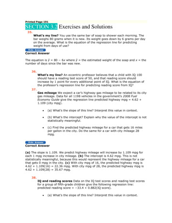
71.00—.50—I1.00—2. Dimensions should be attached to the viewthat best shows the contour of the featureto be dimensioned.
4.752.001.50to be dimensioned.that best shows the.50—F1.00Correct,‘1.00—contour of the feature2. Dimensions should be attached to the view
0I.3)C.2Cl)Ca)C.) —0% —-—‘-4Lfl0C
.752.001.50“Ii4.50,Jr1.00TCorrect1.00r3. Whenever possible, avoid dimensioning tohidden lines.
a)c,)D0I.—0oa) o00C3)CC0 ——0q—‘-4LI)Ca)E0 —-ae-1Lfl 0
0)-CI.000) bi0C0a;5C0)EC-)00)0
U)0a)Ea)B0—øB —a) C-)L.0C-)OW000c,%.—LC c00Lr)-c-J
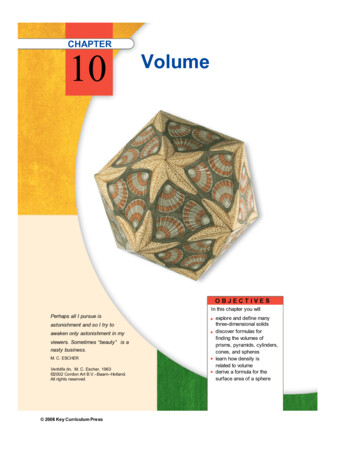
1j1.00—CorrectNotice this dimension is not between the views, but this is a better placementthan dimensioning to the hidden line in the right side view.I475F-2.001.5011.00between adjacent views.5. Whenever possible, locate dimensions
U) cDIIIIq‘—4C)a)‘U 5tbUI.CColb
o.S:IIIII0D‘-4f3H.Ø C1)1b
—FCl)CUG)dI.Ica)—C,)0F %JcuCl)0 CU)f%J0
— -oI 1b‘-4(%4
0C-)bJII0)4bJ-JIULU0 (00)(00.2Cl)a)Eo
(,Qc,)C’.ci)ci)0 .5)C )ci)-c,Cu11%-jo’
a)CCCE15a)-cI-D
0qI Ia)a)Ic-Lq0E0C)0a)Eo —I I
cczIII I I Ia)a)Ic,EIn0C)0a)EoI‘UjI
ci)C-Jci)C’)CDci)-JC)ci F.2U)Ca)Eaci)C-JCmcI,Cci)Eb
—L--——-r—I- ———-—r—— -——i ——r —r——rIi——I I EEEEEL:H—44-F41E— I—— : — —I in.——L .AJ. J.I—i——I———-—IIt.—I.LL.J .L.4 -.JJ .L.————III1 r-r I—.r——i——- ———r—— -r—r——.F - 4-HI—E’EEE EFErEE—I It1 f:1: L—1--t--z---[ tc [ 4EThI- .L4 t4TF—-—E—:I¼ in. scale or 4 squaresPracticeYour Turn to—I-———-——#.L.IIrL.——
ThCl)Cl)C -C)a)-cC)00r4
II11111——;. —II,“4-I:---t-I”rII—I-II—-4— —i--I--I---j””-HO-:J ‘-I:IFHI bz:IIr4--—I:r— — — — — — —II--*—.LI I.--—-4—- —I--.-iI’. i.I-I —- .-1111i.3--.Ilt” r—:;—r———1————;--- F-r()r---I—!-:- 1- -- -- - ��.———--4-I”-F- --,-—-:.II-‘. i—1H-.-------r—i--i--r----1-r- �(10-,.4)Z5Sf2.DCoCl)-QCCDCl)II-
411.41—44I”—’r— — — —1.t. .—4II44—-—‘r—’r-—’--.-4.4. 44I4III4—It.III4—4— II;4.-,---.44 .-4*.*4.3 ., J4I)4I.I44I.,‘.I.I414I444-I -4I4—i14Ia1-414‘iII4ji41.i flfl. 44144.L.——44--.III-- -.444I4144. . --1—,--’,.—44.4. .i.44- — —4——.4.4—4114iII4—1----——-1---r1r —---41-r”--i--44.i,.A.,.4.,.,.4.,. . .J,,.I. ,.I . 4. 4.L. 4., .4.,.3.j I4I-4,.&.4.J.L44444I i-.J,44ITj.b-.4.44I— 444I4III4—.j .,L.4444j4.4.4.b--- — ——--.-44.I.,. t.,.L L.L.4444444-‘1)444.,4.,. .4-. --.i-—“4- ’-”--i---a.I.----.II.4.IIII—-4-4----,-4 -4.-44-r’ i—r -r-4—-—-44.3 -.4.— —L .L.i.I—44144I4——44— -9- . 14.*-.——--IIIIIIIIIII*I141.,.I4---—r —r—.-.-4-tH-I. .L.44—II.1. —‘.14.L .L. L—-—,-.-1--r’4Here They Are
PO)LCTLEDTHEwGatewayToTechnoIoqyActivity 1.4.5 DimensioningIntroductionDimensions are as important as the shapes that you sketch. In order to accuratelyreproduce a part, the manufacturer must know the proper size and the properlocation for all features. This includes the overall height, width, and depth of anobject, as well as the size and location of all other features.There are dozens of rules and guidelines associated with dimensioning. You willlearn how to apply just eight of these in order to make your sketches easy foranyone to understand.Equipment GTT notebookPencilEraserStraight edgeProcedureIn this activity you will begin by following along as your teacher presents informationon dimensioning. Then you will apply your knowledge of dimensioning to identifymissing dimensions on orthographic drawings. Last, you will practice sketching anddimensioning in orthographic from an isometric sketch. Make sure to follow thedimensioning guidelines.1. Why is it necessary to dimension a sketch?2. What dimensions are needed to fully describe a sketch?3. When using ¼ in. graph paper, each square equals ¼ in. or .25 in. How manysquares are in:o1 in. squareso2 in. squareso23,4in. squareso1 1/4in.squaresGTT—Unit 1—Project Lead The Way, Inc.copyright 2010Lesson 4—Activity 1.4.5 Dimensioning Page 1——
4. Now convert number of squares to a linear measurement. Again, each squareequals ¼ in. or .25 in.o7squares inchesol2squares incheso3 squares incheso9 squares inches5. Dimension the following sketch.Each square on the graph equals ¼ in.r——.— —I—-L.t .-tr.-.I I. jJ 1——Ir—-I-—.- r--,IILL—.1IIIIFI6.GTT—Unit 1—Project Lead The Way, Inc.Copyright 2010Lesson 4— Activity 1.4.5 Dimensioning Page 2——
Dimensions must fully describe an object so that someone else can reproduce it.Fill in the missing dimensions on the sketch below. Each square on the graphrepresents ¼ in. Be careful not to over-dimension. Each feature should bedimensioned for size and location only once.ti!r11II1 --i—-i-.—!I-.1 .11rrr.—.-i--- --i--rIi--rIr r-r1-.1.,-rrr11,L1.p15OIIIIi—.i--I- -r —rIL LJ.1.L.JI.1 iI.J.II ILL1.1.j.IrIl:iho.:LT7. Follow along as your teacher discusses the presentation on dimensioninggui
Two Dimensional (2D) Having the dimensions of height and width, height and depth, or width and depth only. Two-PointPerspective A realistic way of drawing objects in three dimensions using a horizon li