Transcription
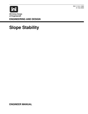
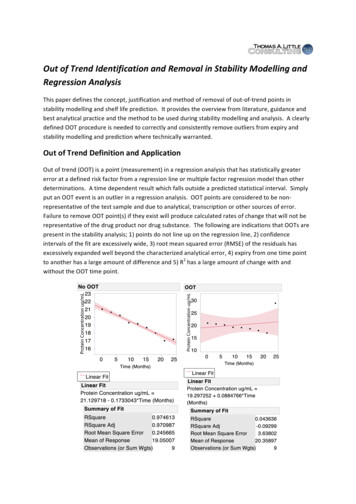
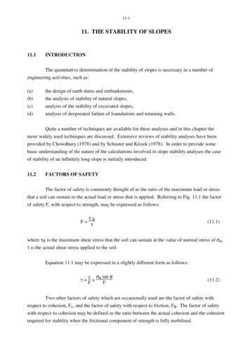
11-111. THE STABILITY OF SLOPES11.1INTRODUCTIONThe quantitative determination of the stability of slopes is necessary in a number ofengineering activities, such as:(a)(b)(c)the design of earth dams and embankments,the analysis of stability of natural slopes,analysis of the stability of excavated slopes,(d)analysis of deepseated failure of foundations and retaining walls.Quite a number of techniques are available for these analyses and in this chapter themore widely used techniques are discussed. Extensive reviews of stability analyses have beenprovided by Chowdhury (1978) and by Schuster and Krizek (1978). In order to provide somebasic understanding of the nature of the calculations involved in slope stability analyses the caseof stability of an infinitely long slope is initially introduced.11.2FACTORS OF SAFETYThe factor of safety is commonly thought of as the ratio of the maximum load or stressthat a soil can sustain to the actual load or stress that is applied. Referring to Fig. 11.1 the factorof safety F, with respect to strength, may be expressed as follows:τF ffτ(11.1)where τff is the maximum shear stress that the soil can sustain at the value of normal stress of σn,τ is the actual shear stress applied to the soil.Equation 11.1 may be expressed in a slightly different form as follows:c σn tan φτ F F(11.2)Two other factors of safety which are occasionally used are the factor of safety withrespect to cohesion, Fc, and the factor of safety with respect to friction, Fφ. The factor of safetywith respect to cohesion may be defined as the ratio between the actual cohesion and the cohesionrequired for stability when the frictional component of strength is fully mobilised.
11-2This may be expressed as follows:τ cFc σn tan φ(11.3)The factor of safety with respect to friction, Fφ, may be defined as the ratio of the tangentof the angle of shearing resistance of the soil to the tangent of the mobilised angle of shearingresistance of the soil when the cohesive component of strength is fully mobilised. One way inwhich this may be expressed is as follows:τ c σn tan φFφ(11.4)A further factor of safety which is sometimes used is FH, the factor of safety with respectto height. This is defined as the ratio between the maximum height of a slope to the actual heightof a slope and may be expressed as follows:HmaxFH H(11.5)The factors of safety Fc, Fφ, FH are only occasionally used in slope stability analyses.The factor of safety with respect to strength (F) as expressed in equation (11.2), is the one whichis almost universally used in calculations.Fig. 11.1 Definition Diagram for Factor of Safety
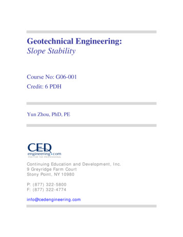
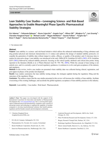
11-3Fig. 11.2 Culmann Aproach to Slope Stability11.3CULMANN METHODA technique for the calculation of slope stability based upon the assumption of a planesurface of failure through the toe of the slope has been proposed by Culmann (see Taylor, 1948).In Fig. 11.2 the line QS represents a plane potential failure surface. The forces acting on thewedge QRS are indicated on the figure as the weight of the wedge W, the mobilised cohesiveforce Cm and the mobilised frictional force P. φm is the mobilised angle of shearing resistance.These three forces are placed in equilibrium to yield the following expression:cmρgH cos (i φm - 2θ) - cos (i - φm)4 cos φm sin i(11.6)where the symbols are indicated in Fig. 11.2. The term on the left hand side of this equation isknown as the stability number. Since QS is an arbitrarily selected trial plane inclined at an angleθ to the horizontal, it is necessary to find the most dangerous plane along which sliding is mostlikely. This is done by setting the first derivative with respect to θ of the expression above equalto zero. This results in determination of the critical inclination θcrit given by the followingexpression:1θcrit 2 (i φm)Substitution of θcrit into equation (11.6) yields the maximum value of the stability number,
11-4cm 1 - cos (i - φm) ρgH 4 cos φm sin i(11.7)The factor of safety with respect to strength may be determined from equation (11.7) by atrial and error process similar to that described in section 11.7.This method of slope stability analysis is not widely used since it has been found thatplane surfaces of sliding are observed only with very steep slopes, and for relatively flat slopes thesurfaces of sliding are almost always curved.EXAMPLEReferring to Fig. 4.2H 16mtan itan θc 2/31/310kPaφ 35 and the weight of the soil wedge QRS is 3.5MN/m. Calculate the factor of safety (F) againstsliding along the potential failure surface QS.For this problem, equation (11.7) is not applicable since the angle (θ) has been specifiedand this may not necessarily be equal to the critical value (θcrit). Equation (11.6) can be used andsubstitution into this equation of the given information yields the following expressioncmcos (φm - 3.18 ) - cos (33.69 - φm) 291.672.219 cos φm(11.8)If equation (11.2) is rewritten asτ cm σn tan φmit is seen that the factor of safety (F) may be expressed asF c/cm tan φ/tan φm(11.9)By using equations (11.7) and (11.9) and using successive approximation the values of φm and cmmay be determined.φm 15.30 and cm 3.91 kPawhich leads to a factor of safety (F) of 2.56.
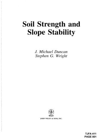
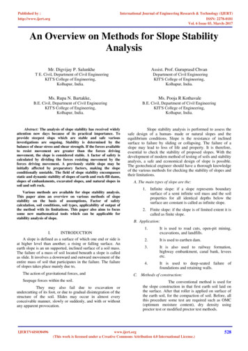
11-5An alternative and possibly simpler technique that may be used for this problem is toexpress the factor of safety (F) in terms of forces instead of stresses.Fwhere CNT maximum forces tending to resist sliding down the plane QSforces tending to cause sliding down the plane QS C N tan φT cohesive force acting on plane QS c x length QS x 1 resolved part of W acting normal to plane QS W cos θ resolved part of W acting down the plane QS W sin θ F 11.4(11.10)10 x 50.6 x 1 3500 x 0.949 x 0.7003500 x 0.3162.56THE φ 0 METHOD OF SLOPE STABILITY ANALYSISSince the surfaces of sliding for many slope failures have been observed to followapproximately the arc of a circle, most of the commonly used analytical techniques for calculationof slope stability involve the assumption of a circular failure arc. Most of the techniquesdiscussed in this chapter are based upon this assumption. For composite failure surfaces, analyseshave been developed by Morgenstern and Price (1965) and by Janbu (1973).The problem is illustrated in the upper part of Fig. 11.3. The forces acting on the slidingwedge of soil are the weight W, normal stresses which act around the failure surface and resistingshear stresses τ which also act around the failure surface. The factor of safety F may be definedfor this situation as follows:
11-6F sum of moments of maximum resisting forcessum of moments of moving forcesτmax x arc length x RWd(11.11)In this equation the moments have been taken about the centre of the circle, part of which formsthe failure surface so that the normal stresses do not enter into the calculation.It will be noted that in equation (11.11) the maximum shear stress (τmax) has beenassumed to be a constant. If this shear stress varies with the position along the sliding surface, itwould be necessary to integrate the shear stress around the arc for use in equation (11.11).In the special case where the slope is formed of a saturated clay the angle of shearingresistance (φu) will be zero for the short term case. The maximum resisting shear stress aroundthe failure arc will then be equal to the undrained cohesion (cu). If the undrained cohesion is aconstant around the failure surface then equation (11.11) may be rewritten as follows:F cu R x arc lengthWd(4.12)This total stress analysis is commonly referred to as the φu 0 method. This method has beenwidely and successfully used in practice for the evaluation of the short term stability of saturatedclay slopes. For example, Ireland (1954) has demonstrated the validity of this technique in theanalysis of the short term stability of a slope excavated in saturated soil.For the case where the angle of shearing resistance is not equal to zero the situation is notas straightforward as described above because of the necessity to determine the frictionalcomponent of the resisting shear stresses. For this case the forces acting on the block are shownin the lower part of Fig. 11.3. These forces (derived from effective stresses) are:(a)the mobilised cohesion force (C'm), for which the line of action is known and themagnitude of which can be expressed in terms of the effective cohesion (c') and thefactor of safety (F),(b)the effective normal force (N'), the magnitude and line of action of which are unknownsince it depends upon the distribution of the normal effective stress around the circulararc,
11-7Fig. 11.3 Forces Involved in Calculations for Stability of SlopesFig. 11.4
11-8(c)Rφ which is the frictional force acting around the arc. This force is normal to the forceN', has a magnitude equal to N' tan φ'/F where φ' is the effective angle of shearingresistance, but the line of action of this force Rφ is unknown. U, the pore pressure force,is known from seepage or other considerations.This means that there are four unknowns altogether, the factor of safety F, the magnitudeof N', the direction of N', and rφ to locate the line of action of the frictional force Rφ. Since thereare only three equations of static equilibrium, this problem is indeterminate to the first degree. Inorder to solve the problem some assumption has to be made to remove one of the unknowns. Onecommonly made assumption involves the distribution of the normal effective stress around thefailure arc. This will enable the direction of the effective normal force N' to be evaluated.EXAMPLEEvaluate the short term stability for the dam shown in Fig. 11.4. The embankmentconsists of a saturated soil for which the angle of shearing resistance φu 0 and the undrainedcohesion cu 70kN/m2. The calculation is to be carried out for the reservoir depth of 18m andfor the case where the reservoir has been completely emptied.In the calculations, the forces Ww and U will have moments about the centre of the circleand therefore must be evaluated.Evaluating the forces (per m) acting on the block:W 720 x 9.81 7060kN 7.06MNWw 12x 36 x 18 x 1.0 x 9.81 3180kN 3.18MNU 12x 18 x 1.0 x 9.81 x 18 1590kN 1.59MNmaximum cohesive force C cu x arc length 70 x 41.2 x 1.32 3.8MNWhen moments are taken about the centre of the circle, there will be no moments due to thenormal stresses and pore pressures acting around the arc; so these stresses can be ignored.
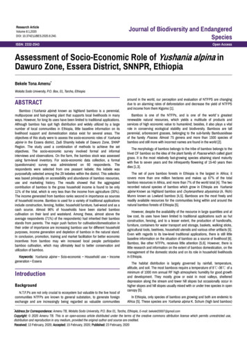
11-9Factor of SafetyF Σ moments of maximum resisting forcesΣ moments of moving forces3.8 x 41.27.06 x 14.8 3.18 x 2 - 1.59 x 34156.6104.5 6.4 - 54.02.75On occasions the force U is considered as a resisting force, in which case,F 156.6 54.0104.5 6.4 1.90This illustrates that a different answer can be obtained depending upon the precise definition ofthe factor of safety. The former calculation yielding a value of F of 2.75 is the more usual onethat is performed.When the water is removed,F 156.6104.5 1.50so the slope will still be stable.11.5ORDINARY METHOD OF SLICESIn cases where the effective angle of shearing resistance is not constant over the failuresurface, such as in zoned earth dams where the failure surface might pass through severaldifferent materials, the friction circle method cannot be used. A 'slices' method, is moreappropriate in this situation. With a method of slices the sliding wedge PQS as shown inFig. 11.5 is subdivided
11-10Fig. 11.5 Illustration of Ordinary Method of Slicesvertically into slices. The factor of safety is determined by examining the contributions to themoving and resisting forces provided by each slice.The forces acting on a typical slice are shown in Fig. 11.5. These forces are the weightof the slice W, the normal and tangential forces acting on the lower boundary of the slice and theside forces indicated by X and E which act on the sides of the slice. With the Ordinary Method ofSlices sometimes known as the Fellenius Method or the Swedish Circle Method (Fellenius(1936), and May and Brahtz (1936)), a number of simplifying assumptions are made in order torender the problem determinate.Firstly it is assumed that the side forces X and E may be neglected and secondly, that the normalforce N, may be determined simply by resolving the weight W of the slice in a direction normal tothe arc, at the mid point of the slice, as shown in the lower part of Fig. 11.5.N W cos αwhere α is the angle of inclination of the potential failure arc to the horizontal at the mid point ofthe slice
11-11Effective normal force N' N-U W cos α - u X sec αtotal maximum resisting force Tmax Factor of SafetyFΣ(c' σ' tan φ') X sec α Σ (c' X sec α N' tan φ') Σ (c' X sec α tan φ' (W cos α - u X sec α)) sum of moments of maximum resisting forcessum of moments of moving forces Σ Tmax RΣ Wd Σ Tmax RΣ W R sin α Σ TmaxΣ W sin α Σ maximum resisting forces around the arcΣ moving forces around the arc Σ (c' X sec α tan φ' (W cos α - u X sec α))Σ W sin α(11.13)This procedure would then be followed for a number of trial failure surfaces until thelowest factor of safety is found.Some difficulties may be experienced with equation (11.13). Negative values of theeffective normal force N' may be encountered for large values of the angle α when pore pressuresare present. This method is widely used by dam constructing authorities even though it has beendemonstrated by Whitman and Moore (1963) and this method of analysis is unsound and yieldsfactors of safety which are smaller than the correct values.
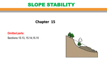
11-12EXAMPLEUsing the Ordinary Method of Slices, determine the factor of safety for the slopeundergoing seepage and for the failure surface shown in Fig. 11.6. The soil properties are asfollows:total density effective cohesion c' effective friction angle φ' 2Mg/m330kN/m230 Fig. 11.6
11-13Fig. 11.7 Stresses and Forces Acting on a Typical SliceThe sliding wedge has been subdivided into six slices as shown in Fig. 11.7. Theweights of the slices
to height. This is defined as the ratio between the maximum height of a slope to the actual height of a slope and may be expressed as follows: FH Hmax H (11.5) The factors of safety F c, F φ, F H are only occasionally used in slope stability analyses. The factor of safety with respect to strength (F) as expressed in equation (11.2), is the one whichFile Size: 406KBPage Count: 20