Transcription
Heuristic Repetitive Activity Scheduling Process forNetworking TechniquesBragadin, M.A.Alma Mater Studiorum – University of Bologna, Italy(email: marcoalvise.bragadin@unibo.it)AbstractProject scheduling is a key activity in construction process. Networking Techniques are usefulinstruments to accomplish project planning and control. But Networking Techniques develop adiscrete model of Construction Process which has instead a continuous nature. New Productiontheories like Critical Chain or Lean Construction recognize this as a major cause of constructionprocess inefficiency. The difference between model and real building process can lead to managingproblems for unexperienced planners, especially in repetitive projects like high rise buildings,housing, highways and other infrastructures, in which crews perform repetitive activities movingfrom one space unit to another. In particular networking techniques minimize construction totalduration but do not satisfy the requirement of work continuity through repetitive units of the project.To satisfy the work continuity constraint many methods have been proposed by researchers andpractitioners. Although the effectiveness of these methods, which give notable insights in repetitiveconstruction process, construction scheduling is still performed in most real cases with a commercialsoftware, working with a CPM based network like Precedence Diagramming Method (PDM). Theobjective of this paper is to present a simple, flexible and easy to implement optimization algorithmfor resource-driven scheduling for repetitive projects. The algorithm is based on a PDM networkplotted on a resource/space chart, thus identifying resource paths and unit paths in the network. Aftertraditional PDM time analysis is performed, the algorithm seeks, for every repetitive activity to beperformed on a repetitive space unit of the project, the Planned Start and the Planned Finish that arebest suitable to satisfy the work continuity requirement. In order to maintain minimum project totalduration the work continuity requirement is relaxed when encountering a network limit. Accordingwith Critical Chain Theory, time buffers are inserted at the end of every resource path, to preventdelays on project completion, due to resource unavailability. The method has been tested on a simplerepetitive project from pertinent literature. The proposed algorithm is an heuristic resource-drivenscheduling method for repetitive projects, easy to be implemented by practitioners.Keywords: repetitive project, resource-constrained scheduling, precedence diagramming method,critical chain, lean construction331
1. Introduction1.1 Precedence Diagramming Method and Repetitive ProjectsConstruction Project scheduling is often accomplished with Activity Network. The most powerfulnetworking technique now available for project planners is Precedence Diagramming Method (PDM)(Harris, 1978) which can be easily implemented with a computer software. PDM is a Critical PathMethod (CPM) networking technique, so it is a construction model in which a set of elements, calledactivities, are linked each other with logical relationships. This construction model representsbuilding process by means of time flow between the network or the sequence of the activities thatconstitutes construction phases. But at the same time it represents another flow in the network, theworkflow. Actually network planning techniques are discrete and time oriented, instead constructionprocess is a continue flow of operations. The success of network planning in term of use byconstruction planners is due to the fact that it is easily implemented by planning computer software,and that its model is well suitable to the traditional conceptualization of construction (Koskela,1992). Construction activities may be repetitive or non repetitive. Repetitive activities are foundcommonly in the construction of high – rise buildings, pipeline networks, highway and housingprojects. A repetitive activity is an activity which is part of a construction sub-process performed byspecialized resources, like for instance plastering or masonry performed by crews in a multi-storeybuilding. In fact, since construction is a continue process accomplished by resources, and thescheduling model (i.e. PDM) is discrete, experienced planners usually design an activity network inwhich construction activities are made discrete by the work assignment of a single constructiveelement, i.e. plaster for storey #1. So the continuous plastering sub-processes is modeled by means ofa repetitive activity, plastering for every storey, i.e. space unit of the building. In a repetitive activitya construction crew often repeats the same work of that activity moving from one repetitive unit toanother (El-Rayes and Moselhi, 1998). A non - repetitive activity is unique in the project and oftencoincide with the whole sub process, i.e. a central boiler installation of a facility (Halpin and Riggs,1992). This kind of project activities, i.e. non repetitive, are easily implemented in network planning,often because of specialized resource utilization. In repetitive-unit projects instead, it is importantthat repetitive activities are planned in such a way as to enable timely movement of crews from onerepetitive unit to the next, avoiding crew idle time. This is known as the “work continuity constraint”and El-Rayes and Moselhi (1998) observe that its application during project planning can provide aneffective resource utilization strategy that leads to: maximization of the benefits from the learningcurve effect for each crew; minimization of idle time of each crew; minimization of the off-onmovement of crews on a project once work as begun.1.2 Repetitive-Unit Project SchedulingAs a matter of fact the struggle of networking techniques to achieve the minimum project totalduration may cause, especially in repetitive projects in which crews are employed from one repetitiveunit to another, resource idle time in construction process. So networking techniques are consideredin literature not suitable for the planning and scheduling of a repetitive project, especially because of332
the inability to satisfy work continuity constraint, even if resource leveling is performed (Selinger,1980; Reda, 1990; Russell and Wong, 1993). The basic instrument suggested by researchers andpractitioners for the planning and scheduling of a repetitive projects are time / space diagrams, inwhich activities performed by resources are plotted as line or other geometrical shape. Researchershave proposed many scheduling methods, that can be classified as Line of Balance for Projects withdiscrete space units, like floors of high – rise building, factory buildings of an industrial plant,housing projects, and Linear Scheduling Method for continuous space projects, like highways andpipeline networks. The first class of repetitive projects is named as “discrete repetitive projects”while the second is named “continuous repetitive projects” (Yang and Ioannou 2001). Kenley andSeppänen (2010) observed that all these methods are more concerned with movement of resourcestrough locations or places, thus they introduced the Location-Based Management System (LBMS)which shifts the focus from individual discrete activities to managing the progress of repetitiveactivities as performed by crews moving through a building and completing all their work location bylocation. Selinger (1980) suggested that there is a tradeoff in scheduling repetitive projects: allowingwork interruptions, thus violating crew work continuity constraint, may reduce the total duration ofconstruction project, and accordingly, indirect cost, while may increase direct cost because of the idlecrew and the learning effects on productivity. Russel and Caselton (1988) extended the work ofSelinger in term of optimizing project duration while relaxing the work continuity constraint. Later,Russell and Wong (1993) suggested that the work continuity constraint should be satisfied but notstrictly enforced in scheduling repetitive activities. In fact they experienced that many of therestrictive assumptions made in model implementing are not really important for practicalimplementation. Real life projects don’t follow the nice, neat parallel lines of a pure flow model, orthe precision portrayed by network diagram. El-Rayes and Mosehli (1998) suggested that resource –driven scheduling accounts directly for crew work continuity and facilitate effective resourceutilization. They suggested that resource – driven scheduling of repetitive activities requires thesatisfaction of three constraint: precedence relationship, crew availability and crew work continuity.Basic concept of resource – driven scheduling of a repetitive project is to account for: a) numbers ofcrews to work simultaneously on different space units of repetitive activities; b) interruption of crewwork continuity. As a matter of fact construction scheduling is still performed, in most cases, with acommercial software, like Primavera Project Planner or MS Project , working with a CPM basednetwork. The objective of this paper is to present a simple, flexible and easy to implementoptimization algorthm for resource-driven scheduling with repetitive and non-repetitive activities.The algorithm is based on a PDM network plotted on a resource/space chart. After traditional CPMtime analysis is performed, the algorithm seeks the planned start and planned finish that are bestsuitable to satisfy the work continuity requirement, for every repetitive activity to be performed on arepetitive space unit of the project. The work continuity requirement is relaxed in order to maintainthe minimum project total duration achieved by CPM time analisys. If it is possible the algorithmcreates time buffers at the end of every resource path. Time buffers are needed to prevent delay onproject completion (Goldratt and Cox, 2004).333
2. New conceptualization of construction2.1 Activity view and flow view of construction processStarting from ages fifty of last century, scientist and researchers have been studying constructionprocess to improve its efficiency and effectiveness. An important branch of research is about methodsand instruments for project planning, scheduling and control. Basically the background of all thismethods and instruments is the traditional conceptualization of construction. Construction is seen as aset of activities characterized by an input and an output, with the objective of producing a certainproduct. This is the “Activity View of Construction” (Koskela, 1992). This model of constructionprocess originates from methods for contract accounting as defined in bidding contracts forcostruction. In fact building facility is divided in subsystems, set of technical compounds. Thequantity surveyor sets relationships between technical elements and cost of manpower, materials andequipment. Actually, for every technical element of the building system it is estimated the cost of theconversion activity, which transforms input in output. The bidding contract sets for the building, orthe building sub-system for sub-contract, the production output, and the prize to be paid, sum ofsingle elements prizes, corresponding to conversion activities. The traditional conceptualization ofconstruction is a model of construction which corresponds to a set of conversion activities, which area set of production sub-processes that convert input in output, each of them realized by specializedcrews and that can be analyzed and managed separately. Lean Construction is a constructionmanagement technique which has the goal of giving more value to the final client by buildingprocesses control. Management focus is on quality of product and processes improvement, waste(muda) reduction, operators responsibility and processes continuous improvement (kaizen).Construction processes are conceptualized as sum of conversion activities and flows of materials,energies, resources and information (Koskela, 1992). Building process conceptualization is nowcomplete: it is the sum of Activity View and Flow View. That is the sum of two basic elements,conversion sub-processes, sets of conversion activities that add more value to the final product, andflow sub-processes, sets of flow activities that move product from one conversion activity to another,normally without value improvement for the final client. More building process efficiency can beachieved by flow activities elimination or reduction, or efficiency improvement of conversionactivities. As a matter of fact networking planning techniques do not model construction flows,especially materials flows and crew flows. So poor planning management can lead to poor flowsmanagement, i.e. waste improvement. An experienced planner usually is well aware of flowprocesses, and keeps these flows as a back requirement of the construction plan (Yi, Lee and Choi,2002).2.2 Goldratt’s Critical ChainGoldratt’s Theory of Constraints (TOC) and its direct application to Project Management, known asCritical Chain Scheduling (Goldratt and Cox 2004, Rand 2000) has recently emerged as a newapproach to operation management. After the first period in the last decade of XX century, whereTOC implementation in project scheduling met with some resistance, TOC approach was found by334
researchers and practitioners to be the new approach to project scheduling that correlates planningtools and human behaviour (Steyn 2000). In fact TOC is a management philosophy that considerhuman behaviour in project planning and execution. Despite that project human resourcemanagement is normally seen as a field of study quite separate from tools and techniques of projecttime management, like Precedence Diagramming Method for example, Critical Chain projectscheduling attempts to account for certain typical human behaviour patterns that affect projectperformance. Critical Chain focuses on the constraints of a project which prevent achieving its goals.Main concept of critical chain scheduling (Herroelen and Leus, 2001) is that critical chain isprotected from time overruns with buffers. So the safety associated with the critical chain activities isshifted to the end of the critical chain in the form of a project buffer, which has the aim of protectingthe project due date promised to the customer from variation in the critical chain activities. Feedingbuffers are placed whenever a non critical chain activity merge into the critical chain both to protectthe critical chain from disruptions on the activities feeding it and to allow critical chain activities tostart early in case things go well. Resource buffers are placed whenever a resource has a job on thecritical chain and the previous critical chain activity is done by a different resource. Resource buffersare usually in the form of an advance warning. The execution of the project is managed through theuse of buffer management. Since there is some predetermined part of buffer remaining unused,everything is assumed to go well, otherwise a corrective action must be taken. The execution ofactivities should be done according to roadrunner mentality: milestones are not used, thus allowing tocapitalize on early finishes of task predecessor. Actually the core concept of critical chain schedulingis the optimization of work flow through the project.3. Heuristic repetitive activity scheduling process fornetworking techniques3.1 Proposed methodConstruction planning with Precedence Diagramming (PDM) method includes three main phases:network realization, time analysis and plan optimization (Harris 1978). In the network realizationphase network logic is defined, i.e. activities and logical relationships between predecessor activitiesand successor activities. In the time analysis phase forward pass is performed, and so early start (ES)and finish (EF) for every activity are computed and the minimum total project duration is found(TPD); then backward pass is performed and so late start (LS), late finish (LF) and floats for everyactivity are computed, and the critical path is found. In this phase feasible dates for activityperformance are detected. In the schedule optimization phase construction programme is modified,searching to achieve project requirements satisfaction, and thus defining the target schedule. Projectschedule optimization may change network logic, activity duration and time constraints. To improveconstruction planning and scheduling with Precedence Diagramming Method an heuristic repetitiveactivity scheduling process is defined, with the aim of supporting an inexperienced planner indefining target plan and schedule for a repetitive project. Project planning with PrecedenceDiagramming ensures logical precedence requirement satisfaction but does not ensure resource flowtracking, nor work continuity constraint satisfaction. These two critical elements of network planning335
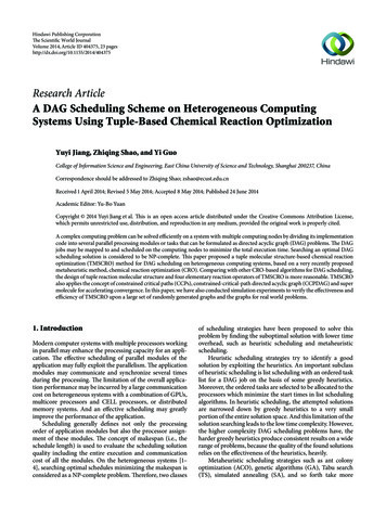
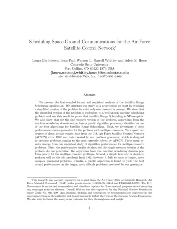
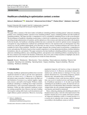
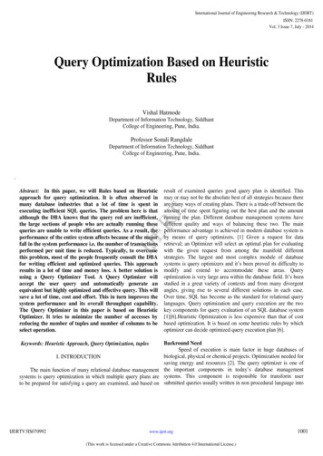
are tackled by the proposed method. Resource flow tracking is improved by network drawing.Network is plotted on a resource / space chart, with the x – axis representing resources and the y –axis representing space units of the project. Crews are grouped by work item, i.e. the repetitiveactivities of masonry, plastering etc. Multiple crews for every work item are allowed in order toperform the same repetitive activity in different space units at the same time. Activities are identifiedby a ij-k code (figure 1) where i identifies the work item, j identifies single crew and k identifies thespace unit in which the activity is performed. An activity of a work item i, performed by the samecrew j in a set of space unit k is called a repetitive activity.UNIT KESEFij-kDlegend:i work itemj crewk space unitD activity durationES early startEF early finishCREW JWORK ITEM IFigure 1: ij-k activity legendThe proposed method assumes that crews of the same work item have the same productivity rate inevery space unit (Harris and Ioannou 1998). Plotting activity network on the resource / space chartenhances resources tracking and make possible to define resource-paths, ij columns of the chart, andunit-paths, k rows of the chart (Yi, Lee and Choi 2002, Moselhi and Hassanein 2004) (figure 2).K2unit pathi1j2-k2i2j1-k2DDresourcepathK1unit pathi1j1-k1i2j1-k1DDCREW j1WORK ITEM i1CREW j2CREW j1WORK ITEM i2Figure 2: Network diagram plotted on a resource – space chartThe work continuity requirement satisfaction is obtained by repetitive activity shifting. To ensurework continuity the proposed method introduce an algorithm that, after usual PrecedenceDiagramming time analysis, i.e. forward pass and backward pass, shifts the start and finish ofrepetitive activity to search for resource continuity, if made possible by network logic. In fact theoptimization algorithm does not modify total project duration (TPD) as computed by traditionalforward pass of Precedence Diagramming. The new start and finish dates are called Planned Start(PS) and Planned Finish (PF). If possible buffers (Time Buffer - TB) are placed at the end of everysub critical resource path ij to protect the critical path from time overruns.336
Idle time of crew, due to work interruption on a resource path ij, between k’ space unit and successork space unit is calculated as the subtraction of the early start of the successor repetitive activity in theunit k and the early finish of the predecessor repetitive activity in the unit k’:Idle ij (k’,k) ESij-k - EFij-k’(eq. 1)where: Idle ij (k’,k) is the idle time of crew ij between unit k’ and successor unit k; ESij-k is the earlystart of the activity ij-k; EFij-k’ is the early finish of the activity ij-k’; k’ is the predecessor spaceunit; k is the successor space unit.Rule 1: if, for every k’, k couple of the resource path ij the Idle ij (k’,k) value is equal to 0, or, forevery activity ij-k of the same resource path ij the total float TFij-k value is equal to 0, theresource path ij is defined critical, although sub – critical.Idle time of work on a space unit path k, between activities performed by ij’ resource and successoractivity performed by ij resource on the same unit path, is calculated as the subtraction of the earlystart of the successor repetitive activity of resource ij and the early finish of the predecessor repetitiveactivity of the resource ij’:Idle k (ij’,ij) ESij-k – EFij’-k(eq. 2)where: Idle k (ij’,ij) is the idle time of work on space unit k between activities performed by resourceij’ and resource ij; ESij-k is the early start of the activity ij-k; EFij’-k is the early finish of the activityij’-k; ij’ is the predecessor resource path; ij is the successor resource path.Rule 2: if, for every ij’-k, ij-k couple of the space path k the Idle k (ij’,ij) value is equal to 0, or,for every activity ij-k of the same space path k the total float TF ij-k is equal to 0, the space pathk is defined critical, although sub – critical.Note that a critical space path or a critical resource path are not critical path in the original CPMsense, because they are usually defined by the idle time (eq. 1 and 2) which does not mean theabsence of total float of the activities (with the exception of the rule 1 and 2, where actually the TFijk is equal to 0) but only the continuity of performance of a chain of activities on a space path or on aresource path. The chain of critical space or critical resource activities can still have float time in theCPM sense. To highlight this difference the original CPM critical path can be called “Time CriticalPath”. If possible time buffers are placed at the end of every resource path to protect fromcontingencies the performance of activities placed on the Time Critical Path, thus preventing delayson project completion.3.2 Scheduling Optimization MethodThe proposed scheduling optimization method has two main phases, in which several steps arefollowed. The proposed algorithm of phase 2 is an heuristic method that search for project337
optimization. The project solution can be sub-optima, but it is a simple method, easy to perform byresearchers and practitioners.PHASE 1 – Path analysis1. Network logic. The PDM network is plotted on a resource – space chart, with the resourcesin the x – axis and space on the y – axis. Activities on the same k row show the work flow inthe space unit (i.e. space path), activities on the same ij column show the work flowperformed by the same crew j of a work item i (i.e. resource path).2. Traditional PDM time analysis. Forward pass and early dates detection (ES and EF),backward pass and late dates detection (LS and LF). Free float and Total float calculation,time critical path detection (TFij-k 0).3. Resource critical path detection (eq. 1 and rule 1).PHASE 2 – Schedule optimization1. Analyze in the latest resource path ij the last activity ij-k:if ij-k is time sub-critical with FFij-k 0 m 0 insert a Time Buffer (TBij) between ijk and its successor, with TBij t m; the value of Planned Start is set to Early Start(PSij-k ESij-k) and the value of Planned Finish is set to Early Finish (PFij-k EFij-k).Then analyze the predecessor ij-k’ with Idle ij (k’, k) 0 and go to step 2;if ij-k is time critical with TFij-k 0, or does not have any free float, (i.e. FFij-k 0), thevalue of Planned Start is set to Early Start (PSij-k ESij-k) and the value of PlannedFinish is set to Early Finish (PFij-k EFij-k). Then consider the predecessor ij-k’ withIdle ij (k’, k) 0 and go to step 2. If every predecessor has Idle ij (k’, k) value equal to 0,go to the earlier resource path ij and re-start from step 1.2. On the resource path ij, for the predecessor activity ij-k’:the Free Float FFij-k’ m is calculated;the Idle Time of crew, due to work interruption between k’ space unit and successor kspace unit (eq. 1) is calculated:Idle ij (k’,k) ESij-k - EFij-k’ nactivity ij-k’ is shifted of Sij-k’; where Sij-k’ min (m, n) s; the Planned Start and thePlanned Finish are calculated as follows:PSij-k’ ESij-k’ Sij-k’338
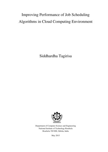
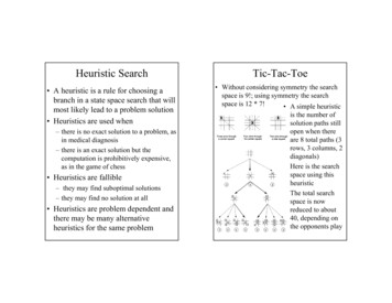
PFij-k’ EFij-k’ Sij-k’the shift Sij-k’ increases Idle ij (k’, k’’) between activity ij-k’ and its predecessor ij-k’’on the same resource path ij, then go to step 3;if the activity ij-k’ has TFij-k’ FFij-k’ 0; or Idle ij (k’, k) 0; the value of PlannedStart is set to Early Start (PSij-k’ ESij-k’), and the value of Planned Finish is set toEarly Finish (PFij-k’ EFij-k’); then go to step 3.3. The ij-k’’ predecessor activity of activity ij-k’ becomes itself ij-k’ of step 2; go to step 2. Ifthere is no predecessor activity ij-k’’ on the same resource path ij go to step 1 and process theearlier resource path ij.4. Sample ApplicationThe proposed method is performed for a simple example. The example concerns a small constructionproject of refurbishment of a five storey building. Three repetitive activity are considered: concreteslab pouring (A), plastering (B) and paving (C). These repetitive activities must be performed bycrews in every space unit of the project. Each space unit is a floor of the building. Every repetitiveactivity is performed by one or more than one crew. The example project has the followingassumptions: only one crew for concrete slab pouring (A1) and for paving (C1), two crews forplastering (B1 and B2). Activity data for the example project are listed in table 1. In every space unitk network logic is due to technological links between activities, so A – concrete slab pouring – ispredecessor of B – plastering – and B is predecessor of C – paving – as shown in the activity networkplotted on a resource / space chart in figure 3. Finish to Start relationships linking repetitive activitiesperformed by the same crew in the different floors of the building trace resource flow in the project.The resource flow is set by project planner and in the example it is starting from unit 1 to unit 5.Proposed optimization method is then performed (figure 3 and 4).Table 1: Example - activity dataRepetitive Activity(i)A - ConcreteSlab PouringB - PlasteringC - 518172152817315181741528175151817Space Unit (k)339
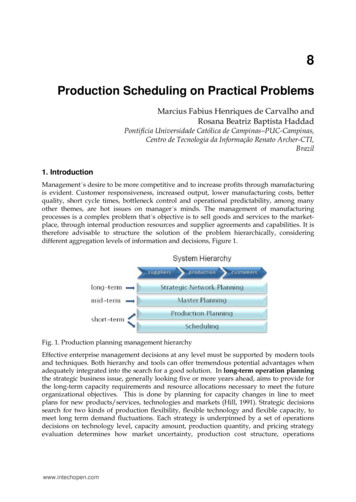
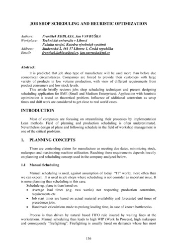
PHASE 1 – Path analysis. The PDM network is plotted on a resource – space chart (figure 3).Forward pass is performed and early dates are detected. Time critical path is formed by ij-k activities:A1-1, B1-1, C1-1, C1-2, C1-3, C1-4, C1-5. Idle time for resource path ij (eq. 1, rule 1) are non-zeroonly: for resource path B2 (Idle B2 (2,4) 20 – 18 2); for resource path B1 (Idle B1 (1,3) 15 – 13 2; Idle B1 (3,5) 25 – 23 2). All resource path C1 is time critical, and so the resource continuityrequirement is satisfied or anyway not optimizable. Resource path A1 is critical in the resource sense(rule 1), and so the resource continuity requirement is already satisfied.PHASE 2 – Schedule optimization. At the end of resource path B2 it is inserted a time buffer equal tothe free float value. The idle working time between unit 2 and successor unit 4 is equal to the freefloat of activity B2-2, which can be shifted of 2 days thus satisfying the resource continuityrequirement for crew B2 (figure 4). At the end of resource path B1 it is inserted a time buffer equal tothe free float value. The idle working time between unit 3 and successor unit 5 is equal to the freefloat of activity B1-3, which can also be shifted of 2 days, thus satisfying the resource continuityrequirement for crew B1. The predecessor of B1-3 on the path B1 is activity B1-1, which has totalfloat equal to 0 and idle working time between unit 1 and successor unit 3 equal to 4 (Idle B1 (1,3) 17 – 13 4). This idle time can not be reduced because activity B1-1 is time critical. Theoptimization of resource path B1 between unit 1 and 3 would need to break at least one of the twoschedule assumptions: maintaining minimum total project duration and/or change the resourceproduction rate for activity B1-1. Anyway work continuity requirement was enhanced in the othertwo cases, for activity B1-3 and B1-5 and for resource path B2. As before mentioned, resource pathA1 is already optimized, like path C1 (figure -1B1-1C1-15871A1LEGEND:TIME SUB 54251CTIME CRITICALESEFIJ-KIJ-KDDFigure 3: Example network diagram - ASAP schedule340
The proposed method has also been tested on a more complex repetitive project from pertinentliterature, showing positive results even in this application.5. ConclusionWith the aim of supporting an inexperienced planner in defining the target plan and schedule for arepetitive project, an heuristic repetitive activity scheduling process has been defined. The proposedmethod works with a CPM based network like Precedence Diagramming Method, and so can beeasily implemented by researchers and practitioners. Two critical elements of network planning aretackled: resource flow tracking and work continuity constraint. The first with network drawing on aresource – space chart, the second with repetitive activity shifting, to search for work continuity. Themethod search for project optimization with an heuristic algorithm, so the found solution can be suboptima, but of simple 587P5P5P13P13P20A1-1B1-1C1-15871A1LEGEND:TIME SUB P52B15P103P25B1-5P154P25A1-52BTIME CRITICALPS1CBUFFERPFIJ-KIJ-KDDTFigure 4: Example network diagram - optimized scheduleReferencesEl Rayes K., Moselhi O. (1998) Resource-driven scheduling of repetitive activities ConstructionManagement and Economics, 16, 433-446.Goldratt E. M., Cox J. (2004) The goal: a process of ongoing improvement Gower, Aldershot U.K.Halpin D. W., Riggs L. S. (1992) Planning and Analysis of Construction Operations Wiley, NewYork U.S.A.341
Harris R.
commercial software, like Primavera Project Planner or MS Project , working with a CPM based network. The objective of this paper is to present a simple, flexible and easy to implement optimization algorthm for resource-driven scheduling with repetitive and non-repetitive activities. The algorithm is based on a PDM network plotted on a .