Transcription
X62082-Brochure 8/15/03 10:09 AM Page 1PowerIT Liquid Filled Single PhasePadmounted Transformers10-250 kVAIndustrialITenabled
X62082-Brochure 8/15/03 10:09 AM Page 2
X62082-Brochure 8/15/03 10:09 AM Page 3Introduction to ABBIndustrialITABB is a global leader in power and automation technologies that enable utility and industry customers to improve their performancewhile lowering their environmental impact.Industrial IT is the ABB name for our commitment to real-time integrated solutions forpower, automation, and information.Distribution TransformersTotal customer satisfaction through continualprocess improvement.ABB Distribution Transformers provide themost complete line of padmounted transformers to meet the applications of any distributionsystem. We are a dominant force in the industry. We lead the way with the introductionof new products and services for the everchanging distribution transformer industry.Our Quality PolicyOur ValuesOur values guide us in how we go about meeting our vision and mission.Customer Success – We seek to provide solutions for mutual competitive advantage. We setthe highest standards for quality, meet deliverycommitments and provide high value.Quality Excellence – We want to be recognizedas a company that exceeds our customers’expectations.We can offer cost-effective solutions for powerdistribution. We support our industry with acommitment to product development. We utilizethe latest manufacturing technology to maintainstate-of-the-art quality and productivity. Largevertical integration allows us to ship high qualityproducts in the shortest possible productioncycle. We are in alliances with major utilities andbusinesses around the world providing productsand services to meet all their needs.ABB will continue to build on a heritage ofquality, customer satisfaction and technology,and capitalize on its resources, to maintain itsposition as the number one supplier of transformers in the industry.ABBABB Quality StrategyStart with a focus on the customer.Measure what is important.Define a benchmark for “highest standardfor quality.”Have a means to dramatically improve performance against the benchmark.3
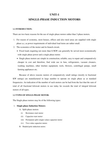
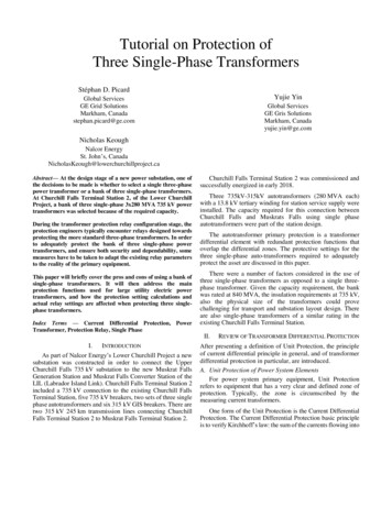
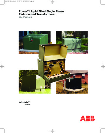
X62082-Brochure 8/15/03 10:09 AM Page 4MTR Mini-Pak Single PhasePadmounted TransformerC57.12.28. The multi-step process includes an epoxyprimer uniformly applied by cationic electrodepositionand a urethane top coat.A single phase, multi-service, low profile padmountedtransformer.The Mini-Pak is designed for cross feed (Type 2) loop feed orradial feed on a grounded wye, underground distributionsystem. It can be furnished in a complete line of ratings andin a wide range of configurations to meet the reliability,safety and operating requirements of any distribution system.The Mini-Pak meets the followingindustry standards:ANSI C57.12.00NEMA TR-1ANSI C57.12.25WUG 2.13, Rev. 4ANSI C57.12.28ANSI C57.12.29ANSI C57.12.70ANSI C57.12.80ANSI C57.12.90ANSI C57.91Ratings @ 65º C Rise:kVA: 10, 15, 25, 37-1/2, 50, 75, 100, 167HV: 4160GY/2400 through 34500GY/19920VBIL: 60, 75, 95, 125 kVLV:240/120, 480/240, 277 V60 hertz standard, 50 hertz optionalStandard Features:1. Equipped with two universal high voltage bushing wellsfor loop feed. (Only one bushing well is provided forradial feed.)2. A flip-top hood and heavy duty 3/8", removable stainlesssteel hinge pins provide safe and durable service.3. A recessed locking assembly with padlock provisionsand a penta-head locking bolt is standard for tamperresistant operation. A hex-head locking bolt is available.4. All tanks are constructed of heavy gauge steel. Tankseams are welded and each unit is pressure tested andinspected for leaks prior to shipment. In addition, allsingle phase transformers are supplied with:a) 5/8" -11 stainless steel lifting bossesb) Oil level/fill plugc) Oil drain plugd) Self-actuating pressure relief devicee) Two ground bosses,1/2" -13 NC tapped hole,7/16" deep5. The front sill latches with the flip-top hood, is attachedon the side of the tank and is removable.6. The high voltage universal bushing wells are externallyclamped and removable. A parking stand between thebushing wells is provided for attachment of bushingaccessories.7. Externally clamped low voltage bushings with contact nuts.8. Tamper-resistant design that exceeds ANSI C57.12.28.9. NEMA safety labels.10. Nameplate.11. The paint finish process applies a durable, corrosionresistant finish to the product. The finish meets orexceeds all the performance requirements of ANSIOptional Accessories:Overcurrent Protection An internal primary protective link to remove the transformer from the system in the event of an internal fault. A secondary breaker provides protection againstsecondary overloads and short circuits. An oil-immersed bayonet-type fuse link to remove thetransformer from the system in case of an internal fault(fault sensing) or secondary short or overload (overloadsensing). This fuse is a drawout design and is supplied inseries with an isolation link. A drip plate is provided toprevent oil from dripping onto the bushing or elbow. A current limiting fuse mounted in a dry well loadbreakcanister. The high interrupting rating of the CL fuse permitsits use on systems where the available fault currentexceeds the ratings of normal expulsion fuses. A partial range current limiting fuse mounted under oilwith the transformer tank. An explusion fuse is supplied in series with the partialrange CL fuse. Available at 95 and 125 kV BIL.Switching Externally-operated tap changer. Externally-operated dual voltage switch. Externally-operated loadbreak oil rotary (LBOR) switch.Primary Connection Universal bushing wells (standard) and loadbreak inserts. Integral (one piece) loadbreak bushings.Secondary Connections Copper studs with contact nuts (standard). Copper studs with rotatable spades. Four-hole, NEMA type, tin-plated copper alloy spade. Four-hole, in line, tin-plated copper alloy spade.Miscellaneous Cleats for anchoring sill to pad. Stainless steel transformer (304 or 400 CB). Stainless steel (“Mini-Skirt”) at base of carbon steel tank. Composite hood, one piece enclosure Conduit hole (not available with composite hood). Provisions for fault indicator.Minimum/Maximum Design Dimensions(Actual dimensions will vary according to voltage, loss evaluation, and 9.25Design Dimensions:Recommended PadDimensionsApproximate dimensions. Dimensions are in inches.Front ViewSide ViewC 6"ACABLE OPENING1.00"B4SILL1.25" FLANGETYP.1.25" SILLFLANGEDC5.0"5.0"B 6"ABB
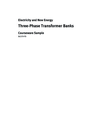
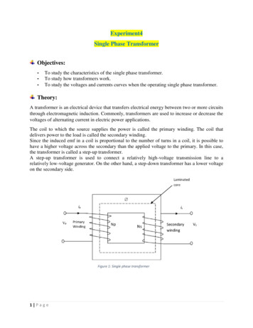
X62082-Brochure 8/15/03 10:09 AM Page 5MTR Maxi-Pak Single PhasePadmounted Transformerexceeds all the performance requirements of ANSIC57.12.28. The multi-step process includes an epoxyprimer uniformly applied by cationic electrodepositionand a urethane top coat.A single phase, multi-service, low profile padmountedtransformer.The Maxi-Pak is designed for loop or radial feed on agrounded wye, underground distribution system. It isdesigned specifically for customers requiring straight-upfeed (Type 1) rather than cross feed (Type 2).The Maxi-Pak meets the followingindustry standards:ANSI C57.12.00ANSI C57.12.80ANSI C57.12.21 - Live frontANSI C57.12.90ANSI C57.12.25 - Dead frontNEMA TR-1ANSI C57.12.28WUG 2.13, Rev. 4ANSI C57.12.29ANSI C57.91ANSI C57.12.70Ratings @ 65º C Rise:kVA: 10, 15, 25, 37-1/2, 50, 75, 100,167, 250HV: 4160GY/2400 through 34500GY/19920VBIL: 60, 75, 95, 125, 150 kVLV:240/120, 120/240, 480/240,240/480, 277 V60 hertz standard, 50 hertz optionalStandard Features:1. Equipped with two universal high voltage bushing wellsfor loop feed. (Only one bushing well is provided forradial feed.)2. A flip-top hood and heavy duty 3/8", removable stainlesssteel hinge pins provide safe and durable service.3. A recessed locking assembly with padlock provisionsand a penta-head locking bolt is standard for tamperresistant operation. A hex-head locking bolt is available.4. All tanks are constructed of heavy gauge steel. Tankseams are welded and each unit is pressure tested andinspected for leaks prior to shipment. In addition, allsingle phase trans-formers are supplied with:a) 5/8" -11 stainless steel lifting bossesb) Oil level/fill plugc) Oil drain plugd) Self-actuating pressure relief devicee) Two ground bosses, 1/2" -13 NC tapped hole,7/16" deep5. The front sill latches with the flip-top hood, is attachedon the side of the tank and is removable.6. The high voltage universal bushing wells are externallyclamped and removable. A parking stand between thebushing wells is provided for attachment of bushingaccessories.7. Externally clamped low voltage bushings with contact nuts.8. Tamper-resistant design that exceeds ANSI C57.12.28.9. NEMA safety labels.10. Nameplate.11. The paint finish process applies a durable, corrosionresistant finish to the product. The finish meets orOptional Accessories:Overcurrent Protection An internal primary protective link to remove the transformer from the system in the event of an internal fault. A secondary breaker provides protection againstsecondary overloads and short circuits. An oil-immersed bayonet-type fuse link to remove thetransformer from the system in case of an internal fault(fault sensing) or secondary short or overload (overloadsensing). This fuse is a drawout design and is supplied inseries with an isolation link. A drip plate is provided toprevent oil from dripping onto the bushing or elbow. A current limiting fuse mounted in a dry well loadbreakcanister. The high interrupting rating of the CL fuse permits itsuse on systems where the available fault currentexceeds the ratings of normal expulsion fuses. A partial range current limiting fuse mounted under oilwith the transformer tank. An explusion fuse is supplied in series with the partialrange CL fuse. Available at 95, 125 and 150 kV BIL.Switching Externally-operated tap changer. Externally-operated dual voltage switch. Externally-operated loadbreak oil rotary (LBOR) switch.Primary Connection Universal bushing wells (standard) and loadbreak inserts. Integral (one piece) loadbreak bushings.Secondary Connections Copper studs with contact nuts (standard). Copper studs with rotatable spades. Four-hole, NEMA type, tin-plated copper alloy spade. Four-hole, in line, tin-plated copper alloy spade. Cable lead secondary.Miscellaneous Cleats for anchoring sill to pad. Stainless steel transformer (304 or 400 CB). Stainless steel (“Mini-Skirt”) at base of carbon steel tank. Conduit hole. Provisions for fault indicator.Minimum/Maximum Design Dimensions(Actual dimensions will vary according to voltage, lossevaluation, and 9.25Design Dimensions:Approximate dimensions. Dimensions are in inches.Front ViewSide ViewRecommended PadDimensionsAC 6"CABLE OPENING1.00"BABBSILL1.25" FLANGETYP.5.0"1.25" SILLFLANGED5.0"B 6"5
X62082-Brochure 8/15/03 10:09 AM Page 6MTR Micro-Pak Single PhasePadmounted Transformer7.8.9.10.11.A single phase, single service, low profile distribution padmount transformer available in loop or radial feed.Designed to aesthetically, safely and economically provideunderground electrical service to single loads, particularly,rural residences, farms and ranches.The Micro-pak meets thefollowing industry standards:ABB padmounted distribution transformers meet the following industry standards:ANSI C57.12.00ANSI C57.12.80ANSI C57.12.25NEMA TR-1ANSI C57.12.28WUG 2.13, Rev. 4ANSI C57.12.29ANSI C57.91ANSI C57.12.70ANSI C57.12.90Externally clamped low voltage bushings with contact nuts.Tamper-resistant design that exceeds ANSI C57.12.28.NEMA safety labels.Nameplate.The paint finish process applies a durable, corrosionresistant finish to the product. The finish meets orexceeds all the performance requirements of ANSIC57.12.28. The multi-step process includes an epoxyprimer uniformly applied by cationic electrode positionand a urethane top coat.Optional Accessories:Overcurrent Protection An internal primary protective link to remove the transformer from the system in the event of an internal fault. An oil-immersed bayonet-type fuse link to remove thetransformer from the system in case of an internal fault(fault sensing) or secondary short or overload (overloadsensing). This fuse is a drawout design and is supplied inseries with an isolation link. An optional drip plate is provided to prevent oil from dripping onto the bushing orelbow.Primary Connection Universal bushing wells (standard) and loadbreak inserts. Integral (one-piece) loadbreak bushings.Secondary Connections Copper studs with contact nuts (standard). Copper studs with rotatable spades. Four-hole, NEMA type, tin-plated copper alloy spade. Four-hole, in line, tin-plated copper alloy spade. Cable lead secondary.Miscellaneous Cleats for anchoring sill to pad. Polypad mounting base. Stainless steel transformer (304 or 400 CB). Stainless steel (“Mini-Skirt”) at base of carbon steel tank. Conduit hole. Provisions for fault indicator.Ratings @ 65º C Rise:kVA: 10, 15, 25, 37-1/2, 50HV: 4160GY/2400 through 24940GY/14400VBIL: 60, 75, 95, 125 kVLV:240/120, 480/240, 277 V, 120/2401,240/480160 hertz standard, 50 hertz optionalStandard Features:1. Equipped with two universal high voltage bushing wellsfor loop feed. (Only one bushing well is provided forradial feed.)2. A flip-top hood and heavy duty 3/8", removable stainlesssteel hinge pins provide safe and durable service.3. A recessed locking assembly with padlock provisionsand a penta-head locking bolt is standard for tamperresistant operation. A hex-head locking bolt is available.4. All tanks are constructed of heavy gauge steel. Tankseams are welded and each unit is pressure tested andinspected for leaks prior to shipment. In addition, allsingle phase transformers are supplied with:a) 5/8" -11 stainless steel lifting bossesb) Oil level/fill plugc) Oil drain plugd) Self-actuating pressure relief devicee) Two ground bosses, 1/2" -13 NC tapped hole,7/16" deep5. The front sill latches with the flip-top hood, is attachedon the side of the tank and is removable.6. The high voltage universal bushing wells are externallyclamped and removable. A parking stand between thebushing wells is provided for attachment of bushingaccessories.Minimum/Maximum Design Dimensions(Actual dimensions will vary according to voltage, loss evaluation, and 6.25Design Dimensions:Approximate dimensions. Dimensions are in inches.Front ViewSide ViewRecommended PadDimensionsAC 6"1.00"1.25" SILLFLANGEB1.25" SILLFLANGETYP.CABLE OPENING5.0"DC5.0"B 6"1Available only with cable lead secondary6ABB
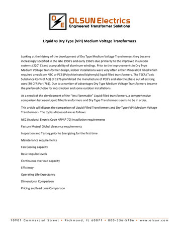
X62082-Brochure 8/15/03 10:09 AM Page 7Composite Hood Single PhasePadmounted TransformerThe innovative composite hood is a one-piece, compressionmolded replacement of the steel hood and sill on the singlephase padmounted transformer. The composite is made offiberglass reinforced, non-conductive, thermosetting resin. Itlatches at a single point to the tank. The system providessignificant operational advantages including more cost effective corrosion protection than stainless steel. It is designedto aesthetically, safely and economically provide underground electrical service.The Composite Hood transformer has passed all ANSIC57.12.28 tamper resistance tests, impact tests at –20º F andtests simulating a high voltage elbow failure. The design meetsC57.12.25. Additional tests were performed to insure that theenclosure would withstand the abuse of string weed trimmersand impact from lawn equipment. It is RUS accepted.The Composite Hood transformer meets thefollowing industry standards:ANSI C57.12.00NEMA TR-1ANSI C57.12.25ANSI C57.12.28ANSI C57.12.29WUG 2.13, Rev. 4ANSI C57.12.70ANSI C57.91ANSI C57.12.80ANSI C57.12.90Ratings @ 65º C Rise:kVA:10, 15, 25, 37-1/2, 50, 75, 100HV:4160GY/2400 through 34500GY/19920VLV:240/120, 480/240, 277 V60 hertz standard, 50 hertz optionalStandard Features:1. The hood is a one-piece, compression molded composite of fiberglass reinforced, non-conductive, thermo-setting resin. The material is corrosion and scratch resistant.2. The elimination of the traditional metal sill providesimproved access to the entire cable area of the transformer.3. During installation, alignment of the transformer on thesupporting pad is easier since the composite does nothave a sill.4. A significant feature is its light weight: about 25 lbs. for acomposite hood compared to 50 lbs. for a steel hood.Due to its light weight, a single operator may open andclose the composite enclosure with little effort. In anergonomic study, it was shown that the compositeenclosure reduced the resultant stress by 10-14% for allbody types and lifting positions compared to the traditional steel hood design.5. Strategically located stiffening ribs help provide thestrength, stiffness and flexibility that is required to meetthe design and function criteria.6. A recessed lock pocket and handle are convenientlylocated at the front, top center of the enclosure anda stainless steel latch plate with attached lock bolt isfastened to the lock pocket.7. At the tank and enclosure interface, a tongue andgroove arrangement insures tamper resistance whenclosed and locked.8. The composite enclosure is non-conductive providingexcellent insulation protection from exposed energizedcables and bushings inside the cable compartment. Theenclosure acts as a shield from animals and insects thatmay hide in the cable area.9. In the case of moderate impact, the composite enclosureis more flexible than steel and less prone to damage.10. All tanks are constructed of heavy gauge steel. Tankseams are welded and each unit is pressure tested andinspected for leaks prior to shipment. In addition, alltransformers are supplied with:a) 5/8" -11 stainless steel lifting bossesb) Oil level/fill plugc) Oil drain plugd) Self-actuating pressure relief devicee) Two ground bosses, 1/2" -13 NC tapped hole,7/16" deep11. The high voltage universal bushing wells are externallyclamped and removable. A parking stand between thebushing wells is provided for attachment of bushingaccessories.12. Externally clamped low voltage bushings with contact nuts.13. NEMA safety labels. (Internal label not in standard location.)14. Nameplate.15. The paint finish process applies a durable, corrosionresistant finish to the product. The finish meets orexceeds all the performance requirements of ANSIC57.12.28. The multi-step process includes an epoxyprimer uniformly applied by cationic electrodepositionand a urethane top coat.Optional Accessories:Overcurrent Protection An internal primary protective link to remove the transformer from the system in the event of an internal fault. An oil-immersed bayonet-type fuse link to remove thetransformer from the system in case of an internal fault(fault sensing) or secondary short or overload (overloadsensing). This fuse is a drawout design and is supplied inseries with an isolation link. A drip plate is provided toprevent oil from dripping onto the bushing or elbow.Primary Connection Universal bushing wells (standard) and loadbreak inserts. Integral (one-piece) loadbreak bushings.Secondary Connections Copper studs with contact nuts (standard). Copper studs with rotatable spades. Four-hole, NEMA type, tin-plated copper alloy spade. Four-hole, in line, tin-plated copper alloy spade. Cable lead secondary.Miscellaneous Stainless steel transformer (304 or 400 CB) tank. Stainless steel 400CB (“Mini-Skirt”) at base of carbon steeltank.A conduit hole and a fault indicator cannot be provided onthe composite hood. Internal stencils and decals cannot beprovided.Anchoring cleats are not provided. The unit may beanchored from the front edges of the tank.ABB7
X62082-Brochure 8/15/03 10:09 AM Page 8Minimum/Maximum Design Dimensions(Actual dimensions will vary according to voltage, loss evaluation, and accessories.)Min.Max.A2424B3234C3342D1717Standard Design 851100Note: For 75 and 100 kVA add 9" for cooling fins.Recommended Pad DimensionsDesign Dimensions:Approximate dimensions. Dimensions are in inches.Front ViewC 6"CABLE OPENING5.0"A5.0"B 6"BINTERFACE TAMPER GROOVEON COMPOSITE ENCLOSURESide View COMPOSITELATCH ARMLATCH ARMBALANCE SPRING SLOTTED CHANNELLATCH ARM SUPPORTDC8Latching Arm (To minimize arm interference during installation andmaintenance, the slotted bracket on the tank permits the arm torotate and be held in a vertical position).ABB
X62082-Brochure 8/15/03 10:09 AM Page 9DistributionTransformer TestingThe ABB commitment to manufacture quality distributiontransformers is backed by a series of transformer tests usedto verify conformance to performance characteristics outlined in the latest revisions of ANSI C57.12.00 and ANSIC57.12.90. These identified tests are also part of the QualitySystem which is audited semi-annually by DET NOSKE VERITAS (DNV) to the ISO Standards.Demag TestSome transformers require the Demag Test to remove anyresidual magnetism in preparation for an impulse test. Italso serves as a no-load exciting current test. A transformerpasses this test if the exciting current does not exceed thelimit specified for the design of the transformer.Applied Voltage Test of the HVThis test checks the dielectric integrity of insulation structures between the high voltage and low voltage, andbetween the high voltage and ground. A pass/fail decision ismade by monitoring the test current intensity. If the resultingcurrent is larger than specified normal leakage and capacitivecurrents, the unit is rejected. This test is omitted for transformers with a permanently grounded high voltage winding.Applied Voltage Test of LVThis dielectric test is similar to the Applied Voltage test ofthe high voltage circuitry except that the integrity of insulation structures between the low voltage and the high voltage, and between the low voltage and ground is checked.A pass-fail decision is made by monitoring the test currentintensity. If the resulting current is larger than specified normal leakage and capacitive current, the unit is rejected.Induced Voltage TestTesting ProgramFactory tests are performed on a transformer to confirmthat it is properly designed and constructed to carry ratedload and that it will withstand the conditions it will beexposed to in service.Each transformer manufactured by ABB must undergo aseries of tests.1. Polarity, Phase-Relation, and Ratio2. Demag Test3. Applied Voltage Test of the HV4. Applied Voltage Test of the LV5. Induced Voltage Test6. No-Load (Excitation) Loss and Excitation Current7. Impedance Voltage and Load Loss8. Full Wave Impulse9. Continuity CheckTest FacilitiesThe multi-station, automated test facilities are operated byprocess control computers. Required interaction with testfloor personnel is minimal with the computers initiating andmonitoring each test, and then analyzing the test resultsfeedback. The computers are programmed to conduct testsaccording to ANSI standards, and according to the ratings ofeach transformer style, the test floor computers will initiateappropriate test setups, compare results with establishedANSI standard limits, and determine acceptance for eachtested unit.The test results for each unit are recorded and stored oncomputer files for access and analysis.Polarity, Phase-Relation, and Ratio TestsThese tests verify proper phase-relation (three phase), ratio,and polarity (single phase) of the transformer under test. Topass, a unit must demonstrate the proper polarity or phaserelation and have a turns ratio within one-half of one percentof the nominal voltage ratio.ABBThe principal purpose of this test is to verify the dielectricstrength of turn to turn, layer to layer, phase to phase, andother insulation structures within the transformer windingsby inducing an overvoltage condition (at higher than normalfrequency to avoid saturation of the core). The test currentis monitored, and if it exceeds limits specified for eachtransformer, the unit is rejected.No-Load Loss and Excitation CurrentThis test measures the no-load (excitation) loss and thetransformer exciting current with rated voltage applied. Ifthe exciting current and/or the no-load loss exceed the limits specified, the transformer is rejected.Impedance Voltage and Load LossThis test measures the load loss and the impedance voltageat rated current. The load loss and the impedance voltagemust be within specified limits.Full Wave ImpulseThe impulse test is one of several tests designed to verifythe dielectric strength of the many insulation structureswithin the distribution transformer against line voltagesurges. It is performed to comply with ANSI standards andfor quality assurance. The change in the ANSI standard in1993 required all manufacturers to install fault detectionsensitive enough to detect a single turn short.Continuity CheckThis test is performed on all transformers to verify transformer circuit and component integrity. This test is performed with an ohmmeter to verify that the internal wiringis correct.The transformer’s nameplate is compared to manufacturinginformation for style, serial number, kVA, HV rating, LV rating, tap voltages, impedance, conductor materials and coilBIL rating. The bushings, electrical accessories, and fuses areverified.9
X62082-Brochure 8/15/03 10:09 AM Page 10Special TestsA. MagnitudeSome tests are performed at the option of the customer.Sound TestingANSI standards define the required sound levels for transformer but some customers specify reduced sound levels.The sound generated by a transformer is affected by the coregeometry, flux density, tank design, and the quality of assembly of all the transformer components into a completed unit.Sound tests are made with the unit powered at 100% and110% of rated voltage under no-load conditions.Temperature TestsCore losses and coil losses are the primary sources of heating within the transformer. Our transformers are guaranteedto have an average coil winding temperature of no morethan 65 C rise over ambient air temperature when operatedat rated voltage and load conditions.The temperature test is performed to determine the thermal characteristics of the transformer and to verify that theyare within design limits.CalibrationTest equipment is calibrated on a scheduled basis by trainedtechnicians. Calibration records are maintained in accordancewith the Quality System procedures. These are audited semiannually by DNV in accordance with ISO Standards.Short Circuit Withstand CapabilitiesDistribution transformers are subjected to external shortcircuits on the secondary side. Such external faults candevelop on the service line, in the house wiring or in connected loads due to numerous environmental reasons.These faults can be line-to-ground, double line-to-ground orline-to-line.To meet these operating conditions, the American NationalStandard Institute (ANSI) has set standards concerning shortcircuit withstand capability. These standards require that distribution transformers shall be designed and constructed towithstand the mechanical and thermal stresses produced bythese external short circuits.The current standards relating to short circuit strength areANSI C57.12.00 which sets the short circuit withstand requirements for distribution transformers and ANSI C57.12.90which provides procedures for short circuit testing.For distribution transformers, the magnitude of the shortcircuit current, the numbers of short-circuit tests and theduration of each short circuit test are defined by ANSI standards as apability*4035251/ZT***Base current (Symmetrical) per unit for all distribution transformerswith secondary rated 600 V and below.**The short circuit current will be limited by the transformerimpedance only.B. Number of TestsEach phase of the transformer shall be subjected to a totalof six tests, four with symmetrical fault currents and twowith asymmetrical fault currents.C. Duration of Short Circuit TestsWhen short circuit tests are performed the duration of eachtest shall be 0.25 s except that one test satisfying the symmetrical current requirement shall be made for a longer durationon distribution transformers. The duration of the long test ineach case shall be as follows:Category I:T 1250/I2Where T is the duration in seconds,And I Isc/IR symmetrical short circuit current, in multiples ofnormal base current except I shall not exceed the maximumsymmetrical current magnitudes listed in A.Where Isc IR/ZT symmetrical short circuit current, in rmsamperesIR rated current on the given tap connection, in rmsamperesZT transformer impedance on the given tap connection inper unit on the same apparent power base as IRCategory II:T 1.0 secondCriteria of Satisfactory PerformanceAccording to ANSI Standards a unit is considered to havepassed the test if it passes a visual inspection and dielectrictests. Recommended additional checks include examinationof wave shape of terminal voltage and current, leakageimpedance measurement and excitation current test. (Referto ANSI C57.12.90.)The standard allows the following variations in the leakageimpedance:ZT (Per Units)0.0299 or less0.0300 or morePercentage Variation22.5-500 (ZT)7.5ZT per unit impedance of the transformer10ABB
X62082-Brochure 8/15/03 10:09 AM Page 11Paint Finish ProcessABB utilizes a multi-step process to apply a corrosion resistant finish to transformers. The materials and processesused are designed to protect against the effects of abrasion,sunlight, rural and industrial atmospheres, and humidity.Each carefully controlled process step has a specific purpose, and each step builds on the previous steps to formthe complete protection system that ensures that our transformers meet ANSI functional p
A single phase, multi-service, low profile padmounted transformer. The Mini-Pak is designed for cross feed (Type 2) loop feed or radial feed on a grounded wye, underground distribution system