Transcription
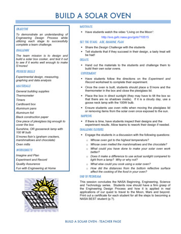
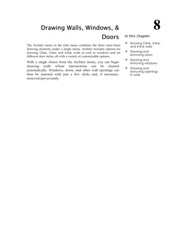
ELECTRIC WALL OVEN INSTALLATION INSTRUCTIONSINSTALLATION AND SERVICE MUST BE PERFORMED BY A QUALIFIED INSTALLER.IMPORTANT: SAVE FOR LOCAL ELECTRICAL INSPECTOR'S USE.READ AND SAVE THESE INSTRUCTIONS FOR FUTURE REFERENCE.FOR YOUR SAFETY: Do not store or use gasoline or other flammable vaporsand liquids in the vicinity of this or any other appliance.CanadaUnited StatesYour new wall oven has been designed to fit a limited variety of cutout sizes to makethe job of installing easier. The first step of your installation should be to measure yourcurrent cutout dimensions and compare them to the cutout dimensions chart below ornext page for your model. You may find little or no cabinet work will be necessary.Do not remove spacers (if equipped) on the side walls and/or on the back of the built-in oven.These spacers center the oven in the space provided. The oven must be centered to prevent excess heat buildupthat may result in heat damage or fire.DO NOT INSTALL A 24" WALL OVEN IN A BASE CABINET WITH A COUNTERTOP ABOVE IT.NOTE: Dimension G is critical to the proper installation of the built-in oven. If the oven decorative trim (ventilation) does notbut against the cabinet, or if noise is heard on convection models, verify dimension G to assure it is according to the requireddimension.Hole for cable andNOTE: For a cutout height greater than H Min. dimension addelectrical junction boxIone 2" (5cm) wide wood shim to each side of the opening underon left side for 30" Wallthe appliance side rails.Ovens.NOTE: Base must be capable ofsupporting 150 pounds (68 kg).** NOTE: Allow at least 19 3/8"C(49.2cm) clearance for door depthwhen it is open.* 24" models: Requireddistance from floor is 31"(78.7cm).30" models: Suggesteddistance from floor is31" (78.7cm). Minimumrequired distance is 4½"(11.4cm).1 1/ 2"(3.8cm)Min.28 3/32"(71.4cm)BHSpacerHole for cable andelectrical junctionbox on right side for24" Wall Ovens.GF3" (7.6cm) Max.31"*(78.7cm)**Door Open(see note)D2" (5.1cm)Min.AFigure 124" AND 30" SINGLE OVENS(Double Ovens see Figure 2)2" (5.1cm) Wide WoodSpacer if NeededElectrical JunctionBox (Right or leftside depending ofmodel)PRODUCT DIMENSIONSMODELABC (wrapper)D24" (61 cm) Wall Oven23 7/8 (60.6)30 3/4 (78.1)21 11/16 (55.1)25 3/8 (64.5)30" (76.2 cm) Wall Oven29 7/8 (75.9)29 7/8 (75.9)28 3/8 (72.1)25 3/8 (64.5)CUTOUT DIMENSIONS AND CABINET WIDTHFMODELHMin.Max.G (Min.)Min.Max.I24" (61 cm) Wall Oven22 (55.9)22 1/4 (56.5)23 1/2 (59.7)28 1/8 (71.4)30 1/8 (76.5)24 (61) Min30" (76.2 cm) Wall Oven28½ (72.4)29 (73.7)24 (61)28 1/4 (71.8)28 7/8 (73.3)30 (76.2) MinSome models are not available in Canada.All dimensions are in inches (cm).Printed in United StatesP/N 318201509 (1001) Rev. F1English – pages 1-8Español – páginas 9-16Français – pages 17-24
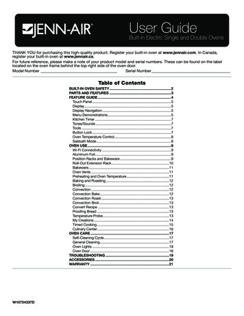
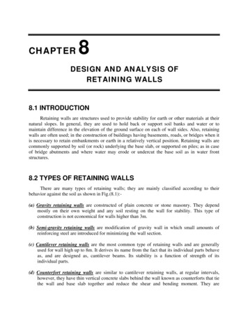
ELECTRIC WALL OVEN INSTALLATION INSTRUCTIONSDo not remove spacers (if equipped) on the side walls and/or on the back of the built-in oven.These spacers center the oven in the space provided. The oven must be centered to prevent excess heat buildupthat may result in heat damage or fire.I1/ 2"1(3.8cm)Min.C47FH3/ 4"Hole for cable and electricaljunction box on left side for30" Wall Ovens.G(121.3cm)BHole for cable and electrical junctionbox on right side for 27" WallOvens.11 1/2"(29.2cm)** Door Open(see note)3" (7.6cm)Max.DElectrical Junction Box(Right or left sidedepending of model)ANOTE: Dimension G is critical to the proper installation ofthe built-in oven. If the oven decorative trim (ventilation)does not but against the cabinet, or if noise is heard onconvection models, verify dimension G to assure it isaccording to the required dimension.2" (5.1cm)Min.NOTE: Base must be capable of supporting 300 pounds (136kg).** NOTE: Allow at least 19 3/8" (49.2cm) clearance for doordepth when it is open.Figure 227" AND 30" DOUBLE OVENS(Single Ovens see Figure 1)* Dimensions for stainless steel models.PRODUCT DIMENSIONSMODELABC (wrapper)D27" (68.6 cm) Wall Oven26 7/8 (68.2) (27 1/8 (68.9))49¼ (125.1)24 11/16 (60.6)25 3/8 (64.5)30" (76.2 cm) Wall Oven29 7/8 (75.9)50 (127)28 3/8 (72.1)25 7/16 (64.6)CUTOUT DIMENSIONS AND CABINET WIDTHFHMODELMin.Max.G (Min.)Min.Max.I27" (68.6 cm) Wall Oven24 7/8 (63.2)25¼ (64.1)23½ (59.7)48 (121.9)49 7/8 (126.7)27 (68.6) Min30" (76.2 cm) Wall Oven28½ (72.4)29 (73.7)24 (61)49 1/8 (124.8)49¾ (126.4)30 (76.2) MinAll dimensions are in inches (cm).Some models are not available in Canada.2
ELECTRIC WALL OVEN INSTALLATION INSTRUCTIONSImportant Notes to the Installer1. Read all instructions contained in these installationinstructions before installing the wall oven.2. Remove all packing material from the ovencompartments before connecting the electrical supplyto the wall oven.3. Observe all governing codes and ordinances.4. Be sure to leave these instructions with the consumer.5. Oven door may be removed to facilitate installation.6. THESE OVENS ARE NOT APPROVED FORSTACKABLE OR SIDE-BY-SIDE INSTALLATION.ApplianceRating ng Watts208VProtectionCircuitRecommendedLess than 4800W20ALess than 4100W20A4800W - 7200W30A4100W - 6200W30A7200W - 9600W40A6200W - 8300W40A9600W and 50A8300W and 50ATable AObserve all governing codes and local ordinances1. A 3-wire or 4-wire single phase 120/240 or 120/208Volt, 60 Hz AC only electrical supply is required on aseparate circuit fused on both sides of the line (redand black wires). A time-delay fuse or circuit breaker isrecommended. DO NOT fuse neutral (white wire). Onlycertain cooktop models may be installed over certainbuilt-in electric oven models. Approved cooktops andbuilt-in ovens are listed by the MFG ID number (see theinsert sheet included in the literature package).Important Note to the ConsumerKeep these instructions with your Owner's Guide forfuture reference.IMPORTANT SAFETY INSTRUCTIONS Be sure your wall oven is installed and groundedproperly by a qualified installer or servicetechnician. This wall oven must be electrically grounded inaccordance with local codes or, in their absence,with the National Electrical Code ANSI/NFPANo.70- latest edition in United States, or with CSAStandard C22.1, Canadian Electrical Code, Part 1,in Canada.NOTE: Wire sizes and connections must conform withthe fuse size and rating of the appliance in accordancewith the American National Electrical Code ANSI/NFPANo. 70-latest edition, or with Canadian CSA StandardC22.1, Canadian Electrical Code, Part 1, and local codesand ordinances.An extension cord should not be usedwith this appliance. Such use may result in a fire,electrical shock, or other personal injury. If you needa longer power cord you can purchase a 10' (3 m) powercord kit #903056-9010 by calling the Service Center.Stepping, leaning or sitting on thedoor of this wall oven can result in serious injuriesand can also cause damage to the wall oven.2. These appliances should be connected to the fuseddisconnect (or circuit breaker) box through flexiblearmored or nonmetallic sheathed cable. The flexiblearmored cable extending from the appliance shouldbe connected directly to the junction box. Thejunction box should be located as shown in Figure1 or Figure 2 and with as much slack as possibleremaining in the cable between the box and theappliance, so it can be moved if servicing is evernecessary.3. A suitable strain relief must be provided to attachthe flexible armored cable to the junction box. Never use your wall oven for warming or heatingthe room. Prolonged use of the wall oven withoutadequate ventilation can be dangerous.The electrical power to the oven mustbe shut off while line connections are being made.Failure to do so could result in serious injury ordeath.1. CarpentryRefer to figure 1 or 2 for the dimensions applicable toyour appliance, and the space necessary to receive theoven. The oven support surface may be solid plywood orsimilar material, however the surface must be level fromside to side and front to rear.Electrical Shock Hazard Electrical ground is required on this appliance. Do not connect to the electrical supply until applianceis permanently grounded. Disconnect power to the junction box before makingthe electrical connection. This appliance must be connected to a grounded,metallic, permanent wiring system, or a groundingconnector should be connected to the groundingterminal or wire lead on the appliance. Do not use a gas supply line for grounding the appliance.Failure to do any of the above could result in a fire,personal injury or electrical shock.2. Electrical RequirementsThis appliance must be supplied with the proper voltageand frequency, and connected to an individual, properlygrounded branch circuit, protected by a circuit breakeror fuse. To know the circuit breaker or fuse requiredby your model, see the serial plate to find the wattageconsumption and refer to table A to get the circuitbreaker or fuse amperage.3
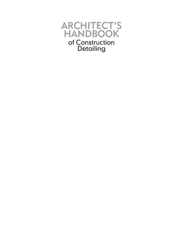
ELECTRIC WALL OVEN INSTALLATION INSTRUCTIONSWait at least three (3) hours afterreceiving this built-in oven before switching the poweron to prevent possible damage to the built-in ovencontrol at power on.OVEN DOOR3. Adjusting Oven HeightA. Models with extension panel (somemodels only):Remove and lay aside the lower vent decorative trimthat is taped to the outer side panel of the oven. Thedecorative trim will be fastened to the lower front ofthe oven after it has been installed in the cabinet.There is a 1 1/2" (3.8cm) height adjustment onmodels with extension panel (see figure 3). With thisadjustment and a 1/2" (1.2cm) trim overhang, a unitcan be installed in existing openings 48" (121.9cm) to50" or 49 7/8" (127cm or 126.7cm) high (for doubleoven) or 28 1/8" (71.4cm) to 30 1/8" (76.5cm) (forsingle oven).OVEN BOTTOMFigure 44. Electrical connectionIt is the responsibility and obligation of the consumer tocontact a qualified installer to assure that the electricalinstallation is adequate and is in conformance with theNational Electrical Code ANSI/NFPA No. 70-latest edition,or with CSA Standard C22.1, Canadian Electrical Code,Part 1, and local codes and ordinances.Risk of electrical shock (Failure to heedthis warning may result in electrocution or other seriousinjury.) This appliance is equipped with copper lead wire.If connection is made to aluminum house wiring, useonly connectors that are approved for joining copper andaluminum wire in accordance with the National ElectricalCode and local code and ordinances. When installingconnectors having screws which bear directly on the steeland/or aluminum flexible conduit, do no tighten screwssufficiently to damage the flexible conduit. Do not overbend or excessively distort flexible conduit to avoidseparation of convolutions en exposure of internal wires.ADJUSTMENTHOLESFigure 3EXTENSION PANELEXTENSIONPANELMOUNTINGSCREWSDO NOT ground to a gas supply pipe. DO NOT connectto electrical power supply until appliance is permanentlygrounded. Connect the ground wire before turning onthe power.To adjust oven height:1. Lay oven on its back. (see figure 4).2. Remove the 6 screws that fasten the sideextension panel to the bottom sides of the oven.3. Move each panel down to the position thatincreases the oven height to fit your opening.Each position changes oven height approximately1/2" (1.3cm).4. Line up the appropriate holes in the side extensionpanels and sides of the oven. Put back the 6screws.5. Proceed with oven installation. Return to uprightposition.B. Models without extension panel (somemodels only):Oven height can be adjusted with 2" (5cm) widewood shims when needed to fit into an existingcabinet cutout opening, when cutout height exceedsH Min. dimension (see Figure 1 or 2).4
ELECTRIC WALL OVEN INSTALLATION INSTRUCTIONSIf oven is used in a new branch circuit installation(1996 NEC), mobile home, recreational vehicle,or where local codes do not permit groundingthrough the neutral (white) wire, the applianceframe MUST NOT be connected to the neutral wireof the 4-wire electrical system. (see figure 6):1. Disconnect the power supply.2. Separate the green (or bare copper) and whiteappliance cable wires.3. In the junction box:connect appliance and power supply cable wires asshown in Figure 6.(If your appliance is equipped with awhite neutral conductor.)This appliance is manufactured with a white neutralpower supply and a frame connected copper wire.The frame is grounded by connection of groundinglead to neutral lead at the termination of theconduit, if used in USA, in a new branch circuitinstallation (1996 NEC), mobile home, recreationalvehicles, where local code do not permit groundingtrough the neutral (white) wire or in Canada,disconnect the white and green lead from eachother and use ground lead to ground unit inaccordance with local codes, connect neutral leadto branch circuit-neutral conductor in usual mannersee Figure 6. If your appliance is to be connectedto a 3 wire grounded junction box (US only),where local code permit connecting the appliancegrounding conductor to the neutral (white) seeFigure 5.NOTE TO ELECTRICIAN: The armored cable leadssupplied with the appliance are UL-recognized forconnection to larger gauge household wiring. Theinsulation of the leads is rated at temperatures muchhigher than temperature rating of household wiring. Thecurrent carrying capacity of the conductor is governed bythe temperature rating of the insulation around the wire,rather than the wire gauge alone.Cable from Power SupplyGroundWireRedWiresGround Wire(Bare orGreen Wire)Model and Serial Number LocationThe serial plate is located along the side of the oven doorin the open position.Cable from Power SupplyWhen ordering parts for or making inquires about youroven, always be sure to include the model and serialnumbers and a lot number or letter from the serial plateon your oven.BlackWiresRedWiresJunctionBoxGround Wire(Bare or Green Wire)BlackWiresWhite WireU.L.-ListedJunction BoxConduitCable from appliance Connector (orCSA listed)Figure 64-WIRE GROUNDED JUNCTION BOXWhere local codes permit connecting the appliancegrounding conductor to the neutral (white) wire(US Only) (see figure 5):1. Disconnect the power supply.2. In the junction box:connect appliance and power supply cable wires asshown in Figure 5.White Wire(Neutral)White WireWhite Wire(Neutral)U.L.-Listed ConduitConnector (or CSA listed)Serial PlateLocationCable from applianceFigure 53-WIRE GROUNDED JUNCTION BOX5
ELECTRIC WALL OVEN INSTALLATION INSTRUCTIONS5. Cabinet InstallationCutout Dimensions28 1/2" (72.4 cm) Min.*29" (73.7 cm) Max.*A. 24" and 27", Single and Double OvensInsert appliance into cutout. Use the screws provided tofasten the front frame of the appliance to the cabinet.The mounting holes in the front frame of appliance maybe used as a template to locate the appliance mountingscrew holes.28 1/16" (71.3 cm) Min.29 5/8" (75.2 cm) Max.To fasten the appliance to the cabinet:1. Line up the 2 mounting holes on the decorative trim(ventilation) (taped to the oven side panel) with thelower mounting holes on each side of the oven frame,below the oven door (see figure 7).2. Use 2 screws from the miscellaneous parts bag tosecure the decorative trim (ventilation) and applianceto the cabinetry.3. Use the remaining 2 screws for mounting theappliance in the upper two mounting holes on eachside of the oven frame, above the door.27 1/4"(71.8 cm) Min.28 7/8"(73.3 cm) Max.Mounting Brackets22"(55.9 cm)21 1/4"(54.0 cm)Wood Shims (If Needed)* Recommended Cutout Width is 28 1/2" (72.4 cm)Figure 830" SINGLE OVENCutout Dimensions28 1/2" (72.4 cm) Min.*29" (73.7 cm) Max.*MOUNTINGSCREWDECORATIVE TRIM(VENTILATION)28 1/16" (71.3 cm) Min.29 7/16" (74.8 cm) Max.MOUNTINGSCREWFigure 7Mounting BracketsB. 30", Single and Double OvensThe wall oven can tip when the dooris open. The mounting brackets supplied with thewall oven must be attached to the cabinet and theappliance to prevent tipping of the wall oven andinjury to persons.42 3/4"(108.6 cm)42"(106.7 cm)Mounting Brackets Installation Instructions1.Unpack the wall oven and find the 2 mounting screwsincluded in the literature package. The door may beremoved to facilitate handling (see the Owner's Guidefor instructions).2.The mounting brackets are temporarily installed underthe decorative side trims of the oven when shipped (seeFigure 8 or 9 ). Remove the mounting brackets from theunit side frame using a No. 2 Robertson screw driver(square drive preferred, however a No. 2 Phillips orQuadrex screw driver can also be used). Open the doorto remove the screws, located at the upper end of theside trim.49 1/8"(124.8 cm) Min.49 3/4"(126.4 cm) Max.Wood Shims (If Needed)* Recommended Cutout Width is 28 1/2" (72.4 cm)Figure 930" DOUBLE OVENS6
ELECTRIC WALL OVEN INSTALLATION INSTRUCTIONS3.Insert the unit into the cabinet opening. Slide unitinward leaving 1 3/8" (3.5 cm) clearance between theoven decorative trim and cabinet. Pull the armored cablethrough the hole in the floor and toward the junction boxwhile moving the appliance inward. Use the second setof holes in the side frame of the unit as a guide to findthe position of the mounting brackets on the sides ofthe cabinet opening. Mark the position of the mountingbrackets as shown in Figure 8 or 9.4.Pull out the oven approximately 1 foot (30.5 cm) awayfrom the cabinet. Reposition each bracket on thecabinet and drill 1/8" pilot holes. Fasten the brackets inplace using the 2 screws supplied (#10 x 1 1/4" long).If needed, add wood spacers at the mounting bracketlocations to reduce the cabinet opening to 28 1/2"(72.4 cm).Now push the unit in and against the cabinet, thenattach the unit to the mounting brackets using the 2screws removed earlier from the side frame.Side filler panels are necessary to isolatethe unit from adjoining cabinets.To reduce the riskof personal injuryand tipping the walloven, the wall ovenmust be secured tothe cabinet(s) byproperly installedmounting screws orbrackets.36" Min.(91.4 cm)GHFUse 3/4" (1.9 cm) plywood, installedon two runners, flush with toe plate.Must be capable of supporting 150pounds. (68 kg).Cut an opening in wood baseminimum 9" x 9" (23 x 23 cm), 2"(5 cm) from left side filler panel,to route armored cable to the walloutlet or junction box.4 1/2"(11.4 cm)Max.CUTOUT DIMENSIONS30" (76.2 cm)Wall OvenF.WIDTHG.DEPTHH.HEIGHT28 1/2" (72.4 cm) Min.29" (73.7 cm) Max.24" (61 cm) Min.28 1/4" (71.8 cm) Min.28 7/8" (73.3 cm) Max.Figure 10 – TYPICAL UNDER COUNTER INSTALLATION OF AN ELECTRIC BUILT-IN OVEN30" SINGLE WALL OVEN ONLY7
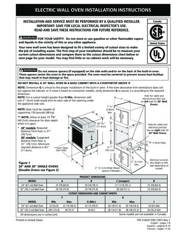
ELECTRIC WALL OVEN INSTALLATION INSTRUCTIONS6. Leveling the Wall OvenBake–After setting the oven to 350 F/177 C for baking,the lower element in the oven should become red.1. Install an oven rack in the center of the upper oven(see Figure 11).2. Place a level on the rack. Take 2 readings with thelevel placed diagonally in one direction and then theother. Use wood shims under the wall oven to level ifnecessary.3. Repeat in the lower oven if you have a double cavitywall oven. If the level indicates that the rack is notlevel, use wood shims to reach a compromise forboth ovens.Broil–When the oven is set to BROIL, the upper elementin the oven should become red.Clean–When the oven is set for a self-cleaning cycle, theupper element should become red during the preheatportion of the cycle. After reaching the self-cleaningtemperature, the lower element will become red.Convection (some models )–When the oven is set fora convection baking or roasting, both elements cycle onand off alternately and the convection fan will turn. Theconvection fan will stop turning when the oven door isopened during convection baking or roasting.IMPORTANT NOTE: A fan inside the upper rear partabove the oven (some models) provides additionalcooling of the oven electrical and electronic components.The fan will continue to run after the oven has beenoperating at high temperatures.Before You Call for ServiceFigure 11Read the Avoid Service Checklist and operatinginstructions in your Owner's Guide. It may save you timeand expense. The list includes common occurrences thatare not the result of defective workmanship or materialsin this appliance.7. Checking OperationSome wall ovens model have Manually OperatedControl Knobs to set the clock and the oven bake, broilconvection (some models) or clean functions. Refer tothe "Owner's Guide" or to the "Oven Control Guide"supplied in the literature package and check all controlsfor correct operation.Refer to the warranty in your Owner's Guide for ourtoll-free service number and address. Please call or writeif you have inquiries about your product and/or need toorder parts.If your model is equipped with an Electronic OvenControl. Each of the functions has been factory checkedbefore shipping. However, it is suggested that you verifythe operation of the electronic oven controls once more.Refer to the Owner's Guide or to the Electronic OvenControl Guide for operation. Follow the instructions forthe Clock, Timer, Preheat, Bake, Broil Convection (somemodels) and Clean functions.8
INSTRUCCIONES DE INSTALACIÓN PARA EL HORNO ELÉCTRICO DE PAREDLA INSTALACIÓN Y EL SERVICIO DEBE DE HACERLOS UN INSTALADOR CALIFICADO.IMPORTANTE: GUARDE ESTAS INSTRUCCIONES PARA USO DEL INSPECTOR ELÉCTRICO LOCAL.LEA Y GUARDE ESTAS INSTRUCCIONES PARA FUTURAS REFERENCIAS.PARA SU SEGURIDAD: No almacene ni utilice gasolina u otros vapores ylíquidos inflamables en la proximidad de este o de cualquier otro artefacto.Su nuevo horno de pared ha sido diseñado para adaptarse a un número diverso de huecoscon distintas medidas, y hacer el trabajo de instalación mas fácil. El primer paso para suinstalación debe de ser el de medir las dimensiones de la apertura actual y compararlascon las que se indican en el cuadro de dimensiones del hueco en el gráfico a continuación,para su modelo. Puede ocurrir que no sea casi necesario hacer trabajo de carpintería.CanadáEstados UnidosNo quite los separadores (si los hay) de los muros laterales o/y de la parte posterior del horno empotrado. Estos espaciadores centran el horno en el espacio provisto. El horno debe estar centrado para prevenir unaconcentración excesiva de calor que podría resultar en daños por el calor o un incendio.NO INSTALE ESTE HORNO 24" EN LA PARTE DE ABAJO DE UN ARMARIO DE COCINA QUE TIENE UN MOSTRADORENCIMA.NOTA: La dimensión G está primordial para instalar correctamente el horno de pared.Si el adorno del armazón del horno no topa contra el armario, o si escuche un ruido,verifique si la dimensión G está en conformidad con la dimensión requerida.NOTA: Para un recortado con altura de más de H Min. dimensión ponga unespaciador de madera de 2" (5 cm) en cada lado de la abertura debajo de las bordaslaterales del artefacto.1NOTA : La basa debe poder sostener 150 libras(68 kg.)C** NOTA: Deje por lo menos 19 3/8" (49.2 cm)de espacio libre para la profundidad de la puertacuando esta abierta.I1 / 2"(3.8 cm)Min.28 3/32"(71.4 cm)B* Modelo de 24": La distancia mínimarequerida desde el suelo es 31" (78.7cm).Modelo de 30: La distancia sugerida desdeel suelo es 31" (78.7cm). La distancia mínima**Puertarequerida es 4½" (11.4cm).EspaciadorGHFAgujero a laderecha parael cable y la cajade empalmeeléctrica parahornos depared de 24’’.3" (7.6 cm)Max.Abierta(vea la nota)DFigura 1MODELOS CON UN SOLO HORNO DE 24" Y 30"(Modelos de horno doble vea la Figura 2)Agujero a la izquierdapara el cable y la caja deempalme eléctrica parahornos de pared de 30’’.31"*(78.7 cm)2" (5.1 cm)Max.APlanchitas de madera de 2"(5.1 cm) (si sea necesario)Caja de empalmeeléctrica (a laderecha o a laizquierda segúnel modelo).DIMENSIONES DEL APARATOMODELOABC (wrapper)DHorno de pared 24" (61 cm)23 7/8 (60.6)30 3/4 (78.1)21 11/16 (55.1)25 3/8 (64.5)Horno de pared 30" (76.2 cm)29 7/8 (75.9)29 7/8 (75.9)28 3/8 (72.1)25 3/8 (64.5)DIMENSIONES DEL HUECO Y ANCHURA DEL ARMARIOFHMODELOMin.Max.G (Min.)Min.Max.IHorno de pared 24" (61 cm)22 (55.9)22 1/4 (56.5)23 1/2 (59.7)28 1/8 (71.4)30 1/8 (76.5)24 (61) MinHorno de pared 30" (76.2 cm)28½ (72.4)29 (73.7)24 (61)28 1/4 (71.8)28 7/8 (73.3)30 (76.2) MinSolamente algunos modelos están disponibles en Canadá.Todas las dimensiones se dan en pulgadas (cm).P/N 318201509 (1001) Rev. FImpreso en los Estados Unidos9English – pages 1-8Español – páginas 9-16Français – pages 17-24
INSTRUCCIONES DE INSTALACIÓN PARA EL HORNO ELÉCTRICO DE PAREDNo quite los separadores (si los hay) de los muros laterales o/y de la parte posterior del hornoemportado. Estos espaciadores centran el horno en el espacio provisto. El horno debe estar centrado para preveniruna concentración excesiva de calor que podría resultar en daños por el calor o un incendio.I1/ 2"1(3.8 cm)Min.CAgujero a la izquierda para el cable yla caja de empalme eléctrica para hornos de pared de 30’’.GFH47 3/4"Agujero a la derecha para el cable y lacaja de empalme eléctrica para hornosde pared de 27’’.(121.3 cm)B11 1/2"(29.2 cm)** Puerta Abierta(vea la nota)3" (7.6 cm)Max.DCaja de empalme eléctrica(a la derecha o a la izquierdasegún el modelo).ANOTA: La dimensión G está primordial para instalar correctamenteel horno de pared. Si el adorno del armazón del horno no topacontra el armario, o si escuche un ruido, verifique si la dimensiónG está en conformidad con la dimensión requerida.2" (5.1 cm)Min.NOTA : La basa debe poder sostener 300 libras (136 kg.)** NOTA: Deje por lo menos 19 3/8" (49.2 cm) de espacio librepara la profundidad de la puerta cuando esta abierta.* Para el modelo de acero inoxidable.Figura 2MODELOS CON UN HORNO DOBLE DE 27" Y 30"(Modelos de horno doble vea la Figure 1)DIMENSIONES DEL APARATOABC (cubierta)DHorno de pared 27" (68.6 cm)26 7/8 (68.2) (27 1/8 (68.9))49 1/4 (125.1)24 11/16 (60.6)25 3/8 (64.5)Horno de pared 30" (76.2 cm)29 7/8 (75.9)50 (127)28 3/8 (72.1)25 3/8 (64.5)MODELODIMENSIONES DEL HUECO Y ANCHURA DEL ARMARIOMODELOMin.F Max.Horno de pared 27" (68.6 cm)24 7/8 (63.2) 25 1/4 (64.1)Horno de pared 30" (76.2 cm)28 1/2 (72.4)29 (73.7)G (Min.)Min.23 1/2 (59.7)48 (121.9)24 (61)Todas las dimensiones se dan en pulgadas (cm).Solamente algunos modelos están disponibles en Canadá.10H Max.I49 7/8 (126.7)27 (68.6) Min49 1/8 (124.8) 49 3/4 (126.4)30 (76.2) Min
INSTRUCCIONES DE INSTALACIÓN PARA EL HORNO ELÉCTRICO DE PAREDNotas importantes para el instalador1.2.3.4.5.6.Lea todas las instrucciones contenidas en este manual antesde instalar el horno.Saque todo el material usado en el embalaje delcompartimiento del horno antes de conectar el suministroeléctrico o de gas a la estufa.Observe todos los códigos y reglamentos pertinentes.Deje estas instrucciones con el consumidor.La puerta del horno se puede quitar para facilitar lainstalación.E S T E H O R N O N O E S T Á A P R O B A D O PA R A L AINSTALACIÓN DE RIMERO O DA LADO A LADO.Grados de Vatiosdel electrodoméstico 240VSe recomiendauna protecciónal circuitoGrados de Vatiosdel electrodoméstico 208VSe recomiendauna protecciónal circuitoMenos de 4800W20AMenos de 4100W20A4800W - 7200W30A4100W - 6200W30A7200W - 9600W40A6200W - 8300W40A9600W and 50A8300W and 50ATable AObserve todos los códigos que gobiernan y ordenanzas locales1. Un cable de 3 o 4 alambres monofásico 120/240 o120/208 voltios, 60 hertzios es la única fuente eléctrica querequiere en un circuito separado en ambos lados de la línea(alambre negro y alambre rojo) (se recomienda un fusibleo un interruptor de retraso de tiempo). No funda a cableneutro (alambre blanco). Se debe de tener precaución alcombinar un horno de pared y una cubierta, refiérase ala placa de seria de cada uno de los aparatos.Nota importante al consumidorConserve estas instrucciones y el manual del usuario parareferencia futura.INSTRUCCIONESIMPORTANTES DE SEGURIDADNOTA: Los tamaños y las conexiones del alambre debenconformarse con el tamaño del fusible y el grado de laaplicación de acuerdo con el código Eléctrico NacionalAmericano ANSI/NFPA No. 70- ultima edición, o conel estándar CSA canadiense C22.1 , código eléctricocanadiense, parte 1, y códigos y ordenanzas locales. Asegúrese de que su horno a pared sea instalada ypuesta a tierra de forma apropiada por un instaladorcalificado o por un técnico de servicio. Este horno de pared debe ser eléctricamente puestaa tierra de acuerdo con los códigos locales o, en suausencia, con el Código Eléctrico Nacional ANSI/NFPA No. 70–última edición en los Estados Unidos, oel Código Eléctrico Canadiense CSA Standard C22.1,Part 1, en Canadá.No se debera usar extensiones paraenchufar este electrodoméstico. Esto podría causarun incendio, choque eléctrico u otro tipo de dañopersonal. Si usted necesita un cable mas largo, puedeordernar un cable de 10" kit 903056-9010 llamando alcentro de Servicio.Pisar, apoyarse, o sentarse sobre lapuerta de este horno a pared puede resultar en seriaslesiones y también puede causar daños al horno apared.2. Este electrodoméstico debe conectarse a la caja de fusibles(o de cortocircuito), por medio de un cable blindado flexibleo un cable con forro no metálico. El cable blindado flexibleque va desde el electrodoméstico debe de estar conectadodirectamente a la caja de empalme. La caja de empalmedebe de estar localizada en el lugar que se indica en laFigura 1 o 2, dejando tanto exceso de cable como seaposible entre la caja y el electrodoméstico, de forma queasí el electrodoméstico se pueda mover fácilmente, si fueranecesario para hacer una reparación.3. Se debe de usar un conector que reduzca la tirantez deuna forma adecuada para unir el cable blindado flexiblea la caja de empalme. Nunca use su horno a pared para calentar el cuarto.El uso prolongado de la estufa sin la ventilación adecuadapuede ser peligroso.La corriente eléctrica al horno debeestar apagada mientras se hacen las conexiones delíneas. Si no se apaga, daños serios o la muerte podríanresultar.1. CarpinteríaConsulte las Figuras 1 y 2 para conocer las dimensiones pertinentes al modelo de su horno y al espacio necesario en el queponer el horno. La superficie donde se va a apoyar el horno debede ser de madera contrachapada sólida u otro material similar
electrical junction box on right side for 24" Wall Ovens. 3" (7.6cm) Max. Electrical Junction Box (Right or left side depending of model) 2" (5.1cm) Min. INSTALLATION AND SERVICE MUST BE PERFORMED BY A QUALIFIED INSTALLER. IMPORTANT: SAVE FOR LOCAL ELECTRICAL INSPECTOR'S US