Transcription
Trade of Sheet MetalworkModule 1: SheetmetalFundamentalsUnit 10: Cylindrical WorkPhase 2
Trade of Sheet Metalwork – Phase 2Module 1Unit 10Table of ContentsList of Figures . 5List of Tables . 6Document Release History . 7Module 1 – Sheetmetal Fundamentals . 8Unit 10 – Cylindrical Work . 8Learning Outcome: . 8Key Learning Points: . 8Training Resources: . 8Exercise: . 9Key Learning Points Code: . 9Bending Rolls. 11Breaking the Grain . 12Preforming . 12Forming Machines . 13Forming Cylinders . 13Plain Bending Rolls . 13Slip Bending Rolls . 14Forming Cylinder with Wired Edges . 14Tinman’s Jenny . 15Flanging a Cylinder . 16Flanging a Disc . 17Forming Sheet Metal . 18Main Aspects of Forming Sheet Metal by Hand . 20Universal Combination Rotary Machine . 21Crimping . 21Swaging Machine . 22Fitting Swaging Rolls . 23Setting Rolls in Correct Alignment. 25Swaging. 26Use of Narrow Gauge . 27Swaging Slip Joint in Ducting . 28Swaging Square or Rectangular Work . 29Swaging Flat Panels for Stiffening Purposes . 30Unit 103
Trade of Sheet Metalwork – Phase 2Module 1Unit 10Joggling . 32Types of Blow Used on Sheet Metal . 33Calculation of Circumference . 33Composition of Forces: Parallelogram Law . 35Self Assessment. 37Answers to Questions 1-5. Module 1.Unit 10. 39Index . 41Unit 104
Trade of Sheet Metalwork – Phase 2Module 1Unit 10List of FiguresFigure 1 - Stretching . 10Figure 2 – Sheetmetal Bending Rolls . 11Figure 3 - Pinch-Type Rollers. 11Figure 4 - Preforming. 12Figure 5 - Forming Cylinders . 13Figure 6 - Slip Bending Rolls . 14Figure 7 - Forming Cylinder with Wired Edges . 14Figure 8 - Tinman's Jenny . 15Figure 9 - Flanging a Disc 1 . 17Figure 10 - Flanging a Disc 2 . 17Figure 11 - Forming Sheet Metal A B . 18Figure 12 - Forming Sheet Metal C . 19Figure 13 – Crimping 1 . 21Figure 14 - Crimping 2 . 21Figure 15 - Swaging Machine . 22Figure 16 - Checking Swage Width . 23Figure 17 - Remove Rolls from Machine . 23Figure 18 - Using the Apron Gauge. 24Figure 19 - Fitting Swaging Rolls. 24Figure 20 - Setting Rolls in Correct Alignment 1 . 25Figure 21 - Setting Rolls in Correct Alignment 2 . 25Figure 22 - Swaging 1 . 26Figure 23 - Swaging 2 . 26Figure 24 - Swaging 3 . 27Figure 25 - Use of Narrow Gauge. 27Figure 26 - Swaging Slip Joint in Ducting. 28Figure 27 - Flatten Notched Portion . 28Figure 28 - Secure Cap . 28Figure 29 - Swaging Square or Rectangular Work . 29Figure 30 - Swaging Flat Panels for Stiffening Purposes 1 . 30Figure 31 - Swaging Flat Panels for Stiffening Purposes 2 . 30Figure 32 - Swaging Flat Panels for Stiffening Purposes 3 . 30Figure 33 - Swaging Flat Panels for Stiffening Purposes 4 . 31Figure 34 - Swaging Flat Panels for Stiffening Purposes 5 . 31Unit 105
Trade of Sheet Metalwork – Phase 2Module 1Unit 10Figure 35 - Joggling . 32Figure 36 - To Divide a Semi-Circle into Equal Parts . 34Figure 37 - Parallelogram Law . 35List of TablesUnit 106
Trade of Sheet Metalwork – Phase 2Module 1Unit 10Document Release HistoryDateVersion07/07/06First draft04/03/142.0Unit 10CommentsSOLAS transfer7
Trade of Sheet Metalwork – Phase 2Module 1Unit 10Module 1 – Sheetmetal FundamentalsUnit 10 – Cylindrical WorkDuration – 14 HoursLearning Outcome:By the end of this unit each apprentice will be able to: Construct a cylinder with a hand grooved joint, flange, and swageDemonstrate use and care of a bending rolls and universal combination rotarymachine (swaging machine)Stretch an edge on a cylinderState the fundamentals of stretchingKey Learning Points:RkUse and care of tools/machinery and equipmentespecially bending rolls and swaging machine(manual/power).Rk PUse of cylindrical forms in sheet metal work.Rk SkBreaking grain of metal.Rk SkPre-forming cylinder.SkEffects of stretching/shrinking on metals.RkAppearance/strengthening effects of swaging.RkMetals - non-ferrous metals and alloys.MCalculations of circumferences/stepping ofmethod (12 divisions)and calculating differencein blank length and finished dia.ScForces/vector diagrams. Parallelogram of forceslaw bows notation.Training Resources: Unit 10Toolkit0.8mm mild steelTools and machinery/equipment Safety equipment and protectiveclothing8
Trade of Sheet Metalwork – Phase 2Module 1Unit 10Exercise:Construct exercise to tolerance shown – Figure 1.Key Learning Points Code:M MathsD DrawingP Personal SkillsSk SkillUnit 10RK Related Knowledge Sc ScienceH Hazards9
Trade of Sheet Metalwork – Phase 2Module 1Unit 10Figure 1 - StretchingUnit 1010
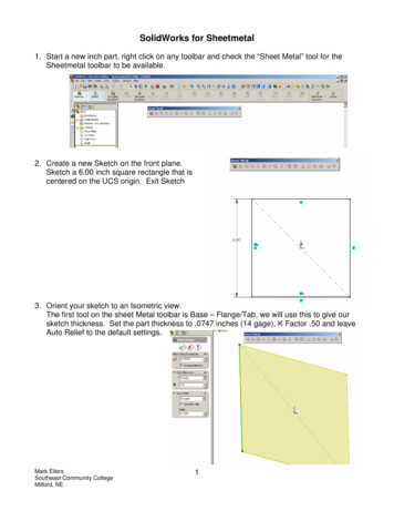
Trade of Sheet Metalwork – Phase 2Module 1Unit 10Bending RollsFigure 2 – Sheetmetal Bending RollsMachines used to bend sheet metal or plate into round or part round forms with eitherparallel or conical sides are called 'Bending Rolls'.Bending rolls for sheet metal are made in various sizes from the bench type for tin platework to the larger pedestal types which are suitable for general sheet-metal work. Thebasic type of rolls used in sheet-metal work is known as the 'Pinch-type Rollers'. Thesemachines have two front rollers which lightly grip (Pinch) and draw the sheet through,and a 'free roller' at the rear to 'set' the metal to the desired radius.There are two kinds of pinch-type rollers:a) Roll-up type: These machines have adjustment in an upward direction on theback roller. This type will roll any size of curvature above the size of the toproll.b) Roll-down type: These machines have adjustment in a downward direction onthe back roller. This type will not roll more curvature than will pass beneaththe pedestal frame of the machine.Figure 3 - Pinch-Type RollersUnit 1011
Trade of Sheet Metalwork – Phase 2Module 1Unit 10The minimum diameter which can be rolled on a rolling machine is in the order of 1½ to2 times the diameter of the roll on which it is being rolled. Most machines roll the metalin an upward direction because this does not restrict the size of the cylinder or curve to berolled. The identification of either kind of pinch-type rollers can easily be determined byvisual inspection, as follows: Where pinch-type rollers have wiring or beading grooves, ifthese grooves are in the top and back rolls, the machine is designed to roll down. Whenthe grooves are in the bottom and back rolls, then the machine is designed to roll up.Breaking the GrainThe first operation when working with light metal should be to 'break the grain' of themetal to prevent ridges forming on its surface. This consists of rolling the piece of metalbackwards and forwards a few times in the rolls, reversing the bending each time. Thisprocess will ensure that the article to be formed by rolling will have a smooth surface freefrom kinks. If this 'breaking' operation is not carried out, a cylindrical or conical articledevelops ridges around the shaped body which, if not seen, may be more easily felt bypassing the palm of the hand over the rolled surface.It is good practice always to break the grain, especially on metals which have been 'coldreduced' before commencing forming operation by rolling.Once the breaking operation is completed the pattern or blank should be rolled out flat inreadiness for forming operations.PreformingWhen we roll metal into a cylindrical shape the edges may not curve the same as the restof the cylinder. We may get two flat bits either side of the joint. To prevent this weperform the metal. This can be done by tapping the edge over a round bar with a mallet asshown in Figure 4.Figure 4 - PreformingUnit 1012
Trade of Sheet Metalwork – Phase 2Module 1Unit 10Forming MachinesForming CylindersThe forming process is begun by inserting the work piece between the two front rolls asshown in Figure 5.Figure 5 - Forming CylindersThe front rolls are adjusted by turning the knuckled adjusting screw on the machine. Thefront rolls should be adjusted to allow just enough clearance between the rolls to avoidcrushing the locks.After the workpiece is inserted, it is tilted upwards as indicated by the diagram. Thisbegins the curve and allows the workpiece to pass between the upper and rear roll.For a large radius, the rear roller is lowered and for a small radius, the rear roll is raised.The rear roll is adjusted by the two adjusting screws located at the rear of the gearhousing at either end of the machine.The two types of bending rolls commonly used in the sheetmetal shop are the plainbending rolls and the slip bending rolls.Plain Bending RollsThe plain bending rolls consists of three rollers through which flat sheets of metal are fedthrough to be formed into cylindrical shapes. The two front rollers are either driven by ahand crank assembly or by an electric motor. Most shops mainly use the hand poweredmachine.The rear or idler roll does the actual forming of the cylinder. It is adjustable up and downto roll the metal to the required diameter.Unit 1013
Trade of Sheet Metalwork – Phase 2Module 1Unit 10Slip Bending RollsThe slip bending rolls works on the same principle as does the plain machine. Thedifference is that the upper roll on the slip machine can be swung away to facilitateremoving the formed object.On both machines the two front rolls operate as feeding and gripping rolls, while the rearroll gives the work its correct curvature. The front rolls are adjusted by adjusting screwsat each end of the machine.The rear roll is adjusted by two screws located at the rear of each housing.The grooves in the front and rear rolls are used when forming objects with wired edges.On the plain bending rolls, the workpiece can only be removed by passing all the waythrough the machine. On the slip bending rolls, the upper roll is released and swungaway, allowing the piece to be slipped off the roll.Figure 6 - Slip Bending RollsForming Cylinder with Wired EdgesWhen forming pails, cans and other round objects with wired edges, the wire shouldextend past the metal slightly at one end. This is the end that should be inserted betweenthe rolls.The wire at the other end should be slightly shorter than the metal to form a pocket toreceive the wire from the other end. A short piece of wire should be inserted to preventthe pocket being smashed. Continue to form the object to the required shape.Figure 7 - Forming Cylinder with Wired EdgesUnit 1014
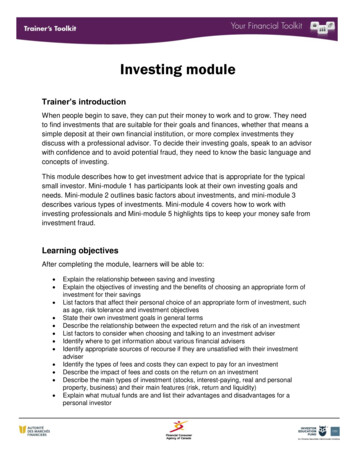
Trade of Sheet Metalwork – Phase 2Module 1Unit 10Tinman’s JennyThis machine is used for turning edges on discs or forming fairly narrow flanges oncylindrical or conical shaped work. The machine is fitted with two rolls, a fine edged top,or pressure roll adjusted by a hand screw, and a recessed bottom or forming roll. Anadjustable guide or gauge is fitted to control accurately the width of required flange.The jenny is normally fitted to a cast iron bench socket but may also be mounted in avice. When mounting, ensure machine is firmly fixed or held. Position so that the handleis at operator's right hand.Hand operated jennies are generally limited to material lighter than 18 S.W.G.Figure 8 - Tinman's JennyUnit 1015
Trade of Sheet Metalwork – Phase 2Module 1Unit 10Flanging a CylinderEnsure cylinder edge is smooth and burr free.Support cylinder in machine and adjust top roll.Turn handle slowly and smoothly maintainingcylinder edge in contact with guide.Tilt cylinder increase turning speed smoothly.Change position of left hand when necessary andcontinue applying upward pressure until flange isat required angle.Note: When long cylinders are being flangedassistance will be necessary. Assistant will raisework to operator’s instructions.Wide flanges will need additional stretching usinga stretching hammer. The work should besupported on a suitable stake.Precaution: When using sharp edged rolls forflanging operations, do not over-tighten the toproll. If the top roll is too tight the metal will besheared. The top roll should be adjusted so as toafford a light grip on the metal between the rolls.The metal in the swaged bead is very highlystressed. This produces a much greaterStrength/Thickness ratio then that of the sheet metalwith which it is formed. In general the maximumthickness of sheet metal which may be swaged is1.62 mm.Unit 1016
Trade of Sheet Metalwork – Phase 2Module 1Unit 10Flanging a DiscSupport disc in left hand, thumb on top, fingers supporting underneath.Light pressure towards centre will maintain disc in contact with guide.Safety: A small piece of metal folded as shown in Figure 9 should be used at all times toprevent injury to operator’s hands. Make sure disc is deburred.Position disc between rolls, edge against preset guide. Using top adjusting screw, lowertop roll until metal is held firmly between rolls.Maintain disc in contact with guide, turn handle clockwise with smooth steady action.Steadily tilt disc slowly upwards until required angle is obtained. Loosen top adjustingscrew and remove disc.Figure 9 - Flanging a Disc 1Figure 10 - Flanging a Disc 2Unit 1017
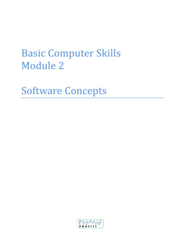
Trade of Sheet Metalwork – Phase 2Module 1Unit 10Forming Sheet MetalThe expression 'forming metal' usually means shaping or bending the material in threedimensions. This is much more difficult than simple bending in two dimensions, for somepart of the metal must be Stretched or Shrunk. Consider a Flange to be put on a curvedsurface, for example a cylinder, as shown in Figure A. It will be apparent that the edge ofthe cylinder, after externally flanging, has a greater circumference than it has before theflange was thrown.Now consider a Flange to be worked up around the edge of a flat metal disc, as shown inFigure B. Here it will be appreciated that the edge of the disc, after flanging, will have asmaller circumference than it had before flanging.In case (A) the metal has been Stretched, whilst in case (B) the metal has been Shrunk orCompressed.By way of contrast, the effects of increasing or decreasing the surface area of one flangeof an angle strip are shown in Figure C. In practice, metal is not generally removed by thesimple expedient of cutting 'Vee' slots. The surface area is reduced by compressing orshrinking the surplus metal. It is more difficult to produce an internally curved flangethan an externally curved one, as it is much easier to stretch metal than to shrink it.Figure 11 - Forming Sheet Metal A BUnit 1018
Trade of Sheet Metalwork – Phase 2Module 1Unit 10Figure 12 - Forming Sheet Metal CUnit 1019
Trade of Sheet Metalwork – Phase 2Module 1Unit 10Main Aspects of Forming Sheet Metal by HandIt’s necessary for the craftsman to possess a thorough basic knowledge of the propertiesof the materials which he has to use.This enables him to understand, and forecast the behaviour of materials under appliedforces, and be in control of the direction of their flow during a particular forming process.Failure to understand these points will result in material, time, and effort being spentproducing faulty shapes, stressed areas, splitting and other undesirable features.The methods employed for shaping work by hand are similar for most materials, the maindifference being concerned with such factors as:a) The Force with which the blow strikes the metal.b) The Direction in which the Force or blow is applied.It should be appreciated that if, for example, a piece of aluminium and a piece of mildsteel sheet of equivalent thicknesses are struck with blows of equal force, the aluminium being softer and more malleable and ductile - will be deformed to a much greater extentthan the mild steel.Since the shaping of sheet metals by hand is essentially a Hammering Process, it isimportant to consider the types of blow which can be struck on sheet metal, and that eachhas its own field of application for particular purposes.Unit 1020
Trade of Sheet Metalwork – Phase 2Module 1Unit 10Universal Combination Rotary MachineCrimpingCrimping is the process used to corrugate one end of a pipe to make it smaller so it willfit easily into the end of another pipe of the same dimension.This method eliminates the need of making one end of the pattern for the pipe smallerthan the other. Crimping can be used on light gauge metal only.Figure 13 – Crimping 1Crimping can be used when turning large flanges on collars since it aids in stretching themetal.Figure 14 - Crimping 2Unit 1021
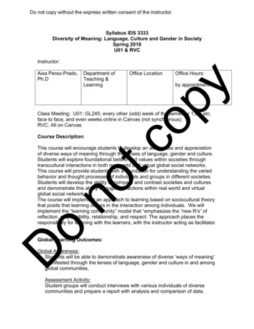
Trade of Sheet Metalwork – Phase 2Module 1Unit 10Swaging MachineSwages are formed on cylindrical objects to serve as stiffeners, reinforcement orornamentation. The swaging machine is a rotary machine equipped with special swagingrolls. The standard shapes of swage are the single, ogee and triple swage.Figure 15 - Swaging MachineBefore operating the machine, if it is powered you must familiarise yourself with thestarting and stopping procedure. Use of different rolls permit the universal rotarymachine to combine the functions of swaging, jennying, wiring, crimping and joggling.The machine may be either hand or power operated.Unit 1022
Trade of Sheet Metalwork – Phase 2Module 1Unit 10Fitting Swaging RollsCheck swage width. Select appropriate size rolls and check that they are free fromdamage or blemishes.Figure 16 - Checking Swage WidthNote: One shaft has a left hand thread, and the securing nut must be unscrewed in theappropriate direction.Remove rolls from machine by unscrewing nut anticlockwise. Remove nut and pull rollsclear of shaft.Figure 17 - Remove Rolls from MachineUnit 1023
Trade of Sheet Metalwork – Phase 2Module 1Unit 10Use the apron gauge when cylindrical work is being swaged, joggled or crimped, close toedge of work.Fit gauge into locating holes on machine frame.Slide gauge clear of shaft ends.Figure 18 - Using the Apron GaugePush swaging rolls on to correct shafts, using spacing collars if necessary. Fit groovedrolls on top shaft for external swage, or a bottom for internal swage.Ensure rolls engage correctly on keys and shafts.Fit nuts noting thread type of direction, then tighten up.Figure 19 - Fitting Swaging RollsUnit 1024
Trade of Sheet Metalwork – Phase 2Module 1Unit 10Setting Rolls in Correct AlignmentLoosen locking ring at handle end of shaft.Fit spanner to screwed bush and adjust bush by turning until alignment is approximatelycorrect.Screw down top rolls adjusting screw until top and bottom rolls engage.Figure 20 - Setting Rolls in Correct Alignment 1Continue adjusting screwed bush until clearance between rolls is even.Tighten nut holding bush to prevent it moving.Set gauge to dimension required, checking dimension from gauge to inside edge ofgroove or roll.Tighten pinch screws.Figure 21 - Setting Rolls in Correct Alignment 2Unit 1025
Trade of Sheet Metalwork – Phase 2Module 1Unit 10SwagingOpen rolls by loosening top roll adjusting screw.Position work between rolls and set against gauge.Tighten adjusting screw until lower roll just marks material.Turn handle keeping work pressed against gauge.Figure 22 - Swaging 1Tighten adjusting screw slightly at each revolution until satisfactory depth of swage isobtained.Note: Assistance may be required for large work. Assistant must keep clear of controland must obey operator's instructions.Figure 23 - Swaging 2Unit 1026
Trade of Sheet Metalwork – Phase 2Module 1Unit 10Swaging cylindrical work with fully grooved joints.Set swage rolls and gauge position work joint close to roll and tighten adjusting screw.Turn handle, keeping work close to gauge.Stop rotation when joint is reached. Slacken off adjusting screw to allow joint to passbetween rolls.Re-position work on other side of joint and continue operations until satisfactory swage isobtained.Figure 24 - Swaging 3Use of Narrow GaugeUse narrow gauge when required line of swage is too far from edge of work to permit useof apron gauge. Fit and adjust as for apron gauge.Figure 25 - Use of Narrow GaugeUnit 1027
Trade of Sheet Metalwork – Phase 2Module 1Unit 10Swaging Slip Joint in DuctingSwaging is often employed to form a seating from slip joints in round ducts. It is usual inthis case to notch the groove allowance to form a lap joint on the slip area.Mark sheet and notch before folding.Figure 26 - Swaging Slip Joint in DuctingFlatten notched portion after folding.Figure 27 - Flatten Notched PortionSecure cap with spot welder or small rivets hammered flat after forming and joining.This operation is also necessary when grooved pipes are to be joggled or crimped.Figure 28 - Secure CapUnit 1028
Trade of Sheet Metalwork – Phase 2Module 1Unit 10Swaging Square or Rectangular WorkSwaging is often used to stiffen rectangular sections, or to locate internal plates. Anexample is shown in Figure 29 of a fuel tank with two internal baffles.Fit swage rolls in correct position. Internal swage is required; therefore grooved roll is onbottom shaft. Adjust narrow gauge to required position.Form baffle swages first.Note: Swage cannot be produced to corner. Re-set gauge to form tank ends and swages.Figure 29 - Swaging Square or Rectangular WorkUnit 1029
Trade of Sheet Metalwork – Phase 2Module 1Unit 10Swaging Flat Panels for Stiffening PurposesUsed to stiffen flat panels, swaging may also be used to remove any slackness present inthe centre of a flat plate.When rounded corners are required for appearance, swage a piece of scrap material tofind the minimum radius that the machine will form.Figure 30 - Swaging Flat Panels for Stiffening Purposes 1Mark off plate to required swage line.Mark corner radii using dividers. Check rolls and form straight swages first.Push gauge clear of rolls to allow free movement of plate when forming radii.Figure 31 - Swaging Flat Panels for Stiffening Purposes 2Loosen adjusting screw and reposition work at start of radius.Increase adjusting screw pressure slightly, carry out this procedure until satisfactoryswage is obtained.Figure 32 - Swaging Flat Panels for Stiffening Purposes 3Unit 1030
Trade of Sheet Metalwork – Phase 2Module 1Unit 10Alternate method of swaging flat panels.Swages may be formed to provide angled corners instead of rounded corners.Mark of plate to required line of swage.Check correct rolls are fitted. Set gauge.Form swage. Stop machine when marked line or previous swage is reached.Note: How swages meet each other.Figure 33 - Swaging Flat Panels for Stiffening Purposes 4Remove work from machine. Select suitable flat top stake. Obtain cross pein hammer.Support work on edge of stake, swage just clear of edge. Using hammer, tap corner toshape avoiding over stretching. Corners should blend smoothly.Figure 34 - Swaging Flat Panels for Stiffening Purposes 5Unit 1031
Trade of Sheet Metalwork – Phase 2Module 1Unit 10JogglingUse joggling wheels to increase or decrease diameters of pipe. Fit selected wheels tomachine. Wheels fitted as shown in Figure 35 will reduce diameter. Adjust lower roll toalign wheels. Allow for material thickness between rolls.Set gauge to size required. Position pipe against guide. Form joggle in stages, tightenrolls at each revolution.Figure 35 - JogglingUnit 1032
Trade of Sheet Metalwork – Phase 2Module 1Unit 10Types of Blow Used on Sheet Metal1. A solid blow: Where the metal is struck solidly over a solid steel head oranvil, a solid blow will stretch the metal.2. An elastic blow: Where either the head or the tool (or both) are made of aresilient material such as wood. An elastic blow will form shee
Bending rolls for sheet metal are made in various sizes from the bench type for tin plate work to the larger pedestal types which are suitable for general sheet-metal work. The basic type of rolls used in sheet-metal