Transcription
DC Electrical Circuits WorkbookJames M. Fiore
2
DC Electrical Circuits WorkbookbyJames M. FioreVersion 1.2.11, 14 April 20203
This DC Electrical Circuits Workbook, by James M. Fiore is copyrighted under the terms of a CreativeCommons license:This work is freely redistributable for non-commercial use, share-alike with attributionPublished by James M. Fiore via dissidentsISBN13: 978-1796779035For more information or feedback, contact:James Fiore, ProfessorElectrical Engineering TechnologyMohawk Valley Community College1101 Sherman DriveUtica, NY 13501jfiore@mvcc.eduFor the latest revisions, related titles, and links to low cost print versions, go to:www.mvcc.edu/jfiore or my mirror sites www.dissidents.com and www.jimfiore.orgYouTube Channel: Electronics with Professor FioreCover art, Some Thing, by the author4
IntroductionWelcome to the DC Electrical Circuits Workbook, an open educational resource (OER). The goal of thisworkbook is to provide a large number of problems and exercises in the area of DC electrical circuits tosupplement or replace the exercises found in textbooks. It is offered free of charge under a Creative Commonsnon-commercial, share-alike with attribution license. This workbook has been replaced by the new text, DCElectrical Circuit Analysis, also OER. The new text features greatly expanded explanations and examplematerial. As such, this workbook will no longer be updated.The workbook is split into several sections, each with an overview and review of the basic concepts and issuesaddressed in that section. These are followed by the exercises which are generally divided into four major types:analysis, design, challenge and simulation. Many SPICE-based circuit simulators are available, both free andcommercial, that can be used with this workbook. The answers to most odd-numbered exercises can be found inthe Appendix. A table of standard resistor sizes is also in the Appendix, which is useful for real-world designproblems. Version 1.1 adds material on dependent sources in Section 6 as well as exercises that can make use ofsupernode/supermesh techniques. If you have any questions regarding this workbook, or are interested incontributing to the project, do not hesitate to contact me.This workbook is part of a series of OER titles in the areas of electricity, electronics, audio and computerprogramming. It includes five textbooks covering DC and AC circuit analysis, semiconductor devices,operational amplifiers, and embedded programming using the C language with the Arduino platform. There areseven laboratory manuals; one for each of the aforementioned texts plus computer programming using thePython language, and the science of sound. The most recent versions of all of my OER texts and manuals may befound at my MVCC web site as well as my mirror site: www.dissidents.comThis workbook was created using several free and open software applications including Open Office, Dia, andXnView.“Insert pithy, droll or historical quote here.”- The Author5
Table of Contents1 Fundamentals.7Significant digits and resolution; scientific and engineering notation; definitions of charge, current,energy, voltage, power, efficiency and resistance; energy cost and battery life; resistor color code.2 Series Resistive Circuits .17.33.45.59.79Circuits using one or more resistors in series with either voltage sources or a current source.3 Parallel Resistive Circuits.Circuits using two or more resistors in parallel with either a voltage source or current sources.4 Series-Parallel Resistive Circuits.Circuits using multiple resistors in series-parallel with either a single voltage source orcurrent source.5 Analysis Theorems and Techniques.Superposition theorem for multi-source circuits, source conversions, Thévenin's and Norton'stheorems, maximum power transfer theorem, delta-Y conversions.6 Mesh and Nodal Analysis, and Dependent Sources .Series-parallel resistor circuits using multiple voltage and/or current sources; dependent sources.7 Inductors and Capacitors.101Definitions for inductors and capacitors, initial and steady-state analysis of RLC circuits, andbasic RL and RC transient response.AppendicesA: Standard Component Sizes .B: Answers to Selected Numbered ProblemsC: Answers to Questions Not Asked6.118.119.128
1 FundamentalsThis section covers: Significant digits and resolution.Scientific and engineering notation.Definitions of charge, current, energy, voltage, power, efficiency and resistance.Energy cost and battery life.Resistor color code.1.0 IntroductionSignificant Digits and ResolutionA key element of any measurement or derived value is the resulting resolution. Resolution refers to thefinest change or variation that can be discerned by a measurement system. For digital measurementsystems, this is typically the last or lowest level digit displayed. For example, a bathroom scale may showweights in whole pounds. Thus, one pound would be the resolution of the measurement. Even if the scalewas otherwise perfectly accurate, we could not be assured of a person's weight to within better than onepound using this scale as there is no way of indicating fractions of a pound.Related to resolution is a value's number of significant digits. Significant digits can be thought of asrepresenting potential percentage accuracy in measurement or computation. Continuing with thebathroom scale example, consider what happens when weighing a 156 pound adult versus a small child of23 pounds. As the scale only resolves to one pound, that presents us with an uncertainty of one pound outof 156 for the adult, but a much larger uncertainty of one pound out of 23 for the child. The 156 poundmeasurement has three significant digits (i.e., units, tens and hundreds) while the 23 pound measurementhas but two significant digits (units and tens).In general, leading and trailing zeroes are not considered significant. For example, the value 173.58 hasfive significant digits while the value 0.00143 has only three significant digits as does 0.000000143.Similarly, if we compute the value 63/3.0, we arrive at 21, with two significant digits. If your calculatorshows 21.0 or 21.00, those extra trailing zeroes do not increase accuracy and are not consideredsignificant. An exception to this rule is when measuring values in the laboratory. If a high resolutionvoltmeter indicates a value of, say, 120.0 millivolts, those last two zeroes are considered significant inthat they reflect the resolution of the measurement (i.e, the meter is capable of reading down to tenths ofmillivolts).7
When performing calculations, the results will generally be no more accurate than the accuracy of theinitial measurements. Consequently, it is senseless to divide two measured values obtained with threesignificant digits and report the result with ten significant digits, even if that's what shows up on thecalculator. For these sorts of calculations, you can't expect the result to be any better than the “weakestlink” in terms of resolution and resulting significant digits.Scientific and Engineering NotationScientific and engineering notations are ways to express numbers without a lot of trailing or leadingzeroes. They also simplify calculations. The idea is to represent the value in two parts: a precisionportion, or mantissa; and the magnitude, a power of ten called the exponent. Thus, 360 can be written as3.6 times 100, or 3.6 102, where 3.6 is the mantissa and 2 is the exponent. Similarly, 0.00275 can bewritten as the value 2.75 times 0.001, or 2.75 10 3. As the base of the exponent is always 10, a morecompact form replaces “ 10” with “E”. Thus, these two values can be written as 3.6E2 and 2.75E-3.When adding or subtracting values in this form, the first step is to make sure that all of the values havethe same exponent. Then, the precision portions are simply added together. Thus, 3.6E2 1.1E2 is 4.7E2.Further, 3.6E2 5E1 is converted as 3.6E2 0.5E2 yielding 4.1E2. Alternately, it can be converted as36E1 5E1 yielding 41E1 (the same answer, 410 in ordinary form). Where this notation is particularlyuseful is when multiplying or dividing. For multiplying, multiply the mantissas and add the exponents.For dividing, divide the mantissas and subtract the exponents. For example, multiply 20000 by 360000.This is equivalent to 2E4 times 3.6E5. The result is 7.2E9 (i.e., 7200000000). Similarly, dividing thevalue 0.006 by 50000 yields 6E 3 divided by 5E4, or 1.2E 7 (or in ordinary form 0.00000012). Noticethe cumbersome and error-prone quantities of trailing and leading zeroes in these examples when usingordinary form.Engineering notation is the same as scientific notation with the caveat that the exponent must by amultiple of 3. Thus, 390000 would be written as either 390E3 or possibly as 0.39E6. Each multiple of 3has a name and abbreviating letter to make the written representation even more compact. The values andnames on12TeraT 3millim (note lower case)9GigaG 6microμ (Greek letter mu)6MegaM 9nanon3kilok 12picopThus, 2000 volts is 2 kilovolts (2 kV) and 0.005 amps is 5 milliamps (5 mA).8
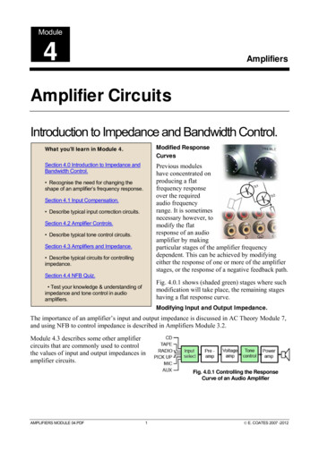
Charge, Current, Energy, Voltage, Power, Efficiency and ResistanceCharge is an attractive force. It is denoted by the letter Q and has units of coulombs. Electrons arenegatively charged and protons are positively charged. All electrons and protons exhibit the samemagnitude of charge, roughly 1.602E 19 coulombs. Thus, one coulomb is equivalent to the chargeexhibited by approximately 1/1.602E 19, or 6.242E18 electrons. Further, opposite charges attract whilelike charges repel, similar to the poles of a magnet.Current is the rate of charge movement. It is denoted by the letter I and has units of amps (or amperes).One amp of current is defined as one coulomb per second. That is, one amp can be visualized asapproximately 6.242E18 electrons passing through a point in a period of one second. Thus, I Q/t. Ifthree coulombs pass through a wire in one-half of a second, this is equivalent to six amps of current.Energy is defined as the ability to do work. It is denoted by the letter W. The basic unit is the joulealthough other units are sometimes used (for example, the calorie or the kilowatt-hour, KWH).Voltage refers to the amount of work (energy) required to move a charge from one point to another. It isdenoted by the letter V (although voltage sources often use E, short for electromotive force or EMF). Thebasic unit is the volt. One volt is defined as one joule per coulomb, thus V W/Q. If 100 joules of energyare used to transfer 20 coulombs of charge, this is equivalent to five volts.Power is the rate of energy usage. It is denoted by the letter P and has units of watts, although other unitsare sometimes used such as the horsepower (1 horsepower 746 watts). One watt is defined as one jouleper second, or P W/t. Thus, if a device consumes 100 joules in 0.1 seconds, the power is 1000 watts orroughly 1.34 horsepower. Power can also be found by multiplying voltage by current. As I Q/t and V W/Q, then the product IV Q/t W/Q, or W/t. Thus, P IV. This is known as power law. For example, if a9 volt battery delivers a current of 0.1 amp, the equivalent power is 0.9 watts.Efficiency is the ratio of useful output power to applied power expressed as a percentage. It is denoted bythe Greek letter η (eta) and is always less than 100%. η Pout/Pin. Thus, if a device draws 200 watts andproduces 120 watts of useful output, its efficiency is 60%, implying that 40% (80 watts) is wasted.Resistance is a measure of how difficult it is to establish current flow (i.e., resistance to current flow). It isdenoted by the letter R and has units of ohms. Ohms are denoted by the capital Greek letter omega, Ω.The reciprocal of resistance is called conductance, G, and has units of siemens. R 1/G and G 1/R.Resistance is a function of the material the current is passing through along with its shape, see Figure 1Aimmediately following, where the arrow shows the direction of current flow.9
lhwFigure 1AR ρ L/A, where ρ (rho) is the resistivity of the material, L is the length and A and the cross sectional area(i.e., the area of the face, or height times width). Resistivity is often specified in ohm-centimeters with thelength and area similarly specified in centimeters and square centimeters, respectively.Resistance can also be defined in terms voltage and current. V I R. This is called Ohm's law and is oneof the most important laws governing practical electrical circuit behavior. Note that Ohm's law and powerlaw may be combined to yield P I2R and P V2/R.Energy Cost and Battery LifeKnowing the voltage and current characteristics of a given device allows us to determine its power ratingand energy consumption. Based on the per unit cost of energy, the cost to operate the device can bedetermined. Although most people refer to their local electricity supplier as “the power company”, we donot buy “power”, per se. Rather, we are billed for energy. Although it would be possible to determine thecost per joule (or more practically, per kilojoule), the supplier normally bills based on kilowatt-hours,KWH. This is because most home appliances are rated in terms of power consumption in watts.Multiplying the power consumption by the length of time the device is used yields a KWH value. Forexample, a 1500 watt toaster oven used for 30 minutes (.5 hours) yields 750 watt-hours, or 0.75 KWH. Ifthe utility charges 10 cents per KWH, then the cost to run the appliance is 7.5 cents. If it is used for a fullhour then it costs 15 cents, and so on.A battery is a device used to store electrical energy. Ideally, it presents a constant voltage, its currentvarying according to the resistance of the device attached to it via Ohm's law. Eventually, the energystored in the battery will be exhausted and its voltage will drop to zero. The storage capacity of a batteryis measured in amp-hours, Ah (or milliamp-hours, mAh, for smaller batteries). Thus, a 10 Ah battery candeliver 10 amps of current for an hour. Alternately, it could deliver 20 amps of current for a half hour, 0.2amps of current for 50 hours, or some other product of time and current that yields 10 Ah. Practicallyspeaking, the efficiency of the battery drops off at very high currents and the lifespan will be somewhatshorter than predicted.10
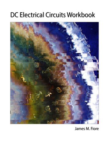
Resistor Color CodeResistors are devices used to control the currents and voltages in a circuit. They are available instandardized ohmic values and at standardized power ratings (see Appendix A). Along with theirresistance value, resistors also have a specified tolerance. This specifies an allowable range of variation ofthe stated value. For example, a 220 ohm resistor may have a tolerance of 10%. This means that theactual value of any given specimen from a box of these resistors may be off of the nameplate or nominalvalue by 10% or 22 ohms. Thus, any particular resistor might be as high as 242 ohms or as low as 198ohms.While high precision resistors often have their nominal value printed directly on them, general purposeresistors use a color code to denote their value and tolerance. Typically, this will involve four colorstripes: two for the precision/mantissa, one for the power of ten, and the fourth to indicate the tolerance.Refer to Figure 1B, immediately following.Figure 1BThe first two bands, here yellow and violet, indicate the precision or leading digits. The third band, hereorange, indicates the power of ten or “number of zeroes” to add. The fourth band, silver in this example,indicates the tolerance. Note that the fourth band is spaced away from the other three to avoidaccidentally reversing the order.The tolerance colors are as follows. A silver tolerance band indicates 10% while gold indicates 5%. Ifthe fourth band is omitted, this indicates a tolerance of 20%. Silver and gold are not used for theprecision bands. If they are used for the multiplier band then gold means “divide by 10” and silver means“divide by 100”.The main colors are 0 black, 1 brown, 2 red, 3 orange, 4 yellow, 5 green, 6 blue, 7 violet, 8 gray,9 white. In the example above, this translates to 4, 7 and 3. The value is “47 with 3 zeroes”, or 47000ohms. The silver fourth band indicates 10% tolerance. Thus, the resistor pictured previously is 47 k ohmswith 10% variation around the nominal value being acceptable. The tolerance yields 4.7 k ohms, so theacceptable range is from 42.3 k ohms to 51.7 k ohms.11
1.1 ExercisesAnalysis1. Round the following to four significant digits: a) 14.5423 b) 30056 c) 76.90032 d) 0.000847542. Round the following to three significant digits: a) 354.005 b) 9100.46 c) 1.0054 d) 0.0000527533. Convert the following to scientific notation: a) 23.61 b) 12000 c) 7632 d) 0.005094. Convert the following to scientific notation: a) 4253 b) 640000000 c) 2.03 d) 0.000006585. Convert the following to engineering notation: a) 12000 b) 470 c) 6.5 d) 0.001986. Convert the following to engineering notation: a) 3500 b) 17.9 c) 5601000 d) 0.00003557. What is the charge in coulombs of a million million (1012) electrons?8. What is the charge in coulombs of 1015 electrons?9. How many electrons would be needed for a charge of 20 coulombs?10. How many electrons would be needed for a charge of 1 microcoulomb?11. If a charge of 2 coulombs passes through a wire in 5 seconds, what is the current?12. If a charge of 300 millicoulombs passes through a wire in 0.1 seconds, what is the current?13. How much charge must be transferred in 0.1 seconds in order to achieve a current of 5 amps?14. How much charge must be transferred in 20 seconds in order to achieve a current of 10microamps?15. Determine the resulting voltage if it takes 2 joules to move 10 coulombs of charge.16. Determine the resulting voltage if it takes 15 joules to move 0.5 coulombs of charge.17. How much energy is required to create a 10 volt potential difference with a 2 coulomb charge?18. How much energy is required to create a 50 millivolt potential difference with a 0.1 coulombcharge?19. What is the wattage equivalent of two horsepower (2 hp)?20. What is the horsepower equivalent of 1000 watts?21. If a device draws 2 amps of current from a 12 volt battery, determine the power delivered.22. If a device draws 10 milliamps of current from a 1.5 volt battery, determine the power delivered.23. A 2 hp motor draws 1800 watts from its source. Determine its efficiency.24. A 5 hp motor draws 4.5 kw from its source. Determine its efficiency.12
25. An audio power amplifier is rated for 500 watts of maximum output at an efficiency of 80%.Determine the amount of wasted power.26. A compressor draws 10 amps of current from a 120 volt source. Its rated output is 1 hp.Determine the efficiency.27. An application requires a battery to deliver 15 mA for at least 200 hours. Determine the requiredamp-hour rating.28. Determine the required rating for a battery to deliver 0.8 A for at least 30 hours.29. A certain 12 volt battery has a rating of 6 Ah. Determine the expected battery life using a 5 mAdraw.30. A certain AA battery has a rating of 800 mAh. Determine the expected battery life using a 20 mAdraw.31. Assume that a certain piece of material has a resistance of 80 ohms. Determine the new resistanceif the length of the piece is doubled and no other parameters are changed.32. Assume that a certain piece of material has a resistance of 2 k ohms. Determine the newresistance if the width and height of the piece are doubled and no other parameters are changed.33. Assume that a certain piece of material has a resistance of 4 ohms. Determine the new resistanceif the resistivity is doubled and no other parameters are changed.34. Assume that a certain piece of material has a resistance of 10 k ohms. Determine the newresistance if the length, width and height of the piece are all halved.35. A certain material has a resistivity of 100 ohm-centimeters. Determine the resistance of a piecethat is 1 cm wide, 0.5 cm high and 6 cm long.36. A certain material has a resistivity of 2000 ohm-centimeters. Determine the resistance of a piecethat is 2 mm wide, 4 mm high and 10 mm long.37. A 40 ohm resistor has dimension of 0.4 cm wide by 0.2 cm high by 1 cm long. Determine theresistivity in ohm-centimeters.38. A 5000 ohm resistor has dimension of 5 mm wide by 3 mm high by 6 mm long. Determine theresistivity in ohm-centimeters.39. A resistor with the color code yellow-violet-red-silver has ameasured value of 4806 ohms. Is this resistor within tolerance? Asa percentage, how far is it from the nominal value?40. A resistor with the color code orange-orange-yellow-gold has ameasured value of 33.9 k ohms. Is this resistor within tolerance?As a percentage, how far is it from the nominal value?41. A resistor with the color code brown-black-orange-silver has ameasured value of 9980 ohms. Is this resistor within tolerance? Asa percentage, how far is it from the nominal value?13Figure 1.1abc
42. A resistor with the color code green-blue-black-gold has a measured value of 50 ohms. Is thisresistor within tolerance? As a percentage, how far is it from the nominal value?43. Determine the value of the resistors pictured in Figure 1.1 (left-toright: red-black-yellow, blue-gray-orange, red-violet-red-silver).44. Determine the value of the resistors pictured in Figure 1.2 (left-toright: red-red-orange-gold, 5. Determine the value of the resistors pictured in Figure 1.3 (left-toright: orange-orange-green-silver, Figure 1.2abc46. Determine the value of the resistors pictured in Figure 1.4 (left-toright: silver-orange-violet-yellow, green-blue-yellow-gold, gold-black-orange-yellow).47. Determine the maximum and minimum allowed values of theresistors pictured in Figure 1-1.Figure 1.348. Determine the maximum and minimum allowed values of theresistors pictured in Figure 1-2.a49. Determine the maximum and minimum allowed values of theresistors pictured in Figure 1-3.b50. Determine the maximum and minimum allowed values of theresistors pictured in Figure 1-4.cDesign51. Determine the resistor color code for the following ohmic valuesusing 10% tolerance: a) 56 Ω b) 33 kΩ c) 470 kΩ d) 1.2 kΩ e)750 Ω52. Determine the resistor color code for the following ohmic valuesusing 5% tolerance: a) 47 Ω b) 22 kΩ c) 390 kΩ d) 2.2 kΩ e)560 ΩFigure 1.4abcChallenge53. A radio transmitter is rated for 100 watts of maximum output at an efficiency of 90%. If it is fedfrom a 120 volt source, determine the current draw.14
54. A certain 75 watt incandescent bulb produces 71 watts worth of heat and the remainder in theform of light. Determine its efficiency as a lighting device and its efficiency as a heating device.55. Assume it takes an 1800 watt toaster 3 minutes to toast a bagel “just right”. If you toast a bagelevery morning for a year and electricity costs 15 cents/ KWH, how much will you have spent inthat year to toast bagels?56. Assume that you can buy standard 60 watt incandescent light bulbs for 50 cents each and thateach has an expected life span of 1000 hours. In comparison, you can buy an LED light bulb thatproduces the same amount of light but only consumes 7 watts. The LED bulbs cost 5.50 eachand have an expected life of 20,000 hours. Assuming electricity costs 14 cents/ KWH, determinethe total cost of running incandescent lights versus LEDs for 40,000 hours.57. Given a 1.5 volt battery with a 500 mAh rating, how much current can it produce continuouslyfor 25 hours?.58. Given a 9 volt battery with a 100 mAh rating, determine the total energy storage in joules.15
Notes 16
2 Series Resistive CircuitsThis section covers: Circuits using one or more resistors in series with either voltage sources or a current source.2.0 IntroductionA series circuit is characterized by a single loop or path for current flow. Consequently, the current is thesame everywhere in a series circuit. As resistors in series add, total resistance may be found by summingthe individual resistors. Multiple voltage sources in series may also be added, however, polarities must beconsidered as opposing voltages partially cancel each other (i.e., adding a negative). In contrast, differingcurrent sources are not placed in series as they would each attempt to establish a different series current, apractical impossibility.Along with Ohm's law, the key law governing series circuits is Kirchhoff's voltage law, or KVL. Thisstates that the sum of voltage rises and voltage drops around a series loop must equal zero (the rises anddrops having opposite polarities). Alternately, it may be reworded as the sum of voltage rises around aseries loop must equal the sum of voltage drops. As a pseudo formula: ΣV ΣV There are multiple techniques for solving series circuits. If all voltage source and resistor values aregiven, the circulating current can be found by dividing the equivalent voltage by the sum of theresistances. Once the current is found, Ohm's law can be used to find the voltage drops across individualresistors. At that point, power law can be used to find the power dissipation in each resistor or the powerdeveloped by the source(s). Alternately, the voltage divider rule may be used to find the voltage dropsacross the resistor(s) of interest. This rule exploits the fact that voltage drops in a series loop will bedirectly proportional to the size of the resistances. Thus, the voltage across any resistor must equal the netsupplied voltage times the ratio of the resistor of interest to the total resistance, VA E RA/RTOTAL.If the circuit uses a current source instead of a voltage source, then the circulating current is known andthe voltage drop across any resistor may be determined directly using Ohm's law.If the problem concerns determining resistance values, the basic idea will be to use these rules in reverse.For example, if a resistor value is needed to set a specific current, the total required resistance can bedetermined from this current and the given voltage supply. The values of the other series resistors canthen be subtracted from the total, yielding the required resistor value. Similarly, if the voltages across tworesistors are known, as long as one of the resistance values is known, the other resistance can bedetermined using either the voltage divider rule or Ohm's law.17
A key item of importance when analyzing series circuits, or indeed any electrical circuit, is noting thepolarity of the voltages. Voltage sources are easy as their polarity is fixed (positive is always at the “longbar” and negative at the “short bar”). The polarity of any resistor will depend on the direction of currentflow. Where conventional current enters a resistor, we denote this with a plus sign, and where the currentleaves, a minus sign. Moving from plus to minus is referred to as a voltage drop. That is, we are movingfrom a more positive or higher potential to a less positive or lower potential, thus “dropping” voltage.Similarly, traversing from minus to plus is called a voltage rise.Along with determining the voltage across single resistors, we are often interested in determining thevoltage between points in a circuit. These may span several components. It is imperative that we know thepolarities of the individual voltages in order to determine the voltage between any two circuit points.The foregoing is illustrated using the series circuit schematic of Figure 2A.Figure 2AHere, the two voltage sources, E1 and E2, aid each other, producing a net voltage of E1 E2. Theirpolarities are fixed. The current direction will be as drawn because conventional current flows out of thepositive terminal of a voltage source. The value of this current will be (E1 E2)/(R1 R2) via Ohm's law.Knowing the direction of current, the polarities of the voltage drops across the two resistors may befound. The point where the current enters the resistor is positive, and negative where it exits. Once theseare labeled, either Ohm's law or the voltage divider rule can be used to determine the voltages developedacross the two resistors. Note that KVL states that the sum of these two voltages must equal the netsupplied voltage, or E1 E2 in this case.To determine the voltage from point a to point c, or Vac, we start at point a and sum the voltage drops andrises until we get to point c. Here, the voltage across R1 shows up as positive ( to ) and the voltageacross E2 shows up as negative ( to ). The result is the voltage across R1 minus the voltage across E2.Depending on the specific values, this may wind up being either a positive or negative value. If it'spositive, this signifies that point a is at a higher potential than is point c. Conversely, if it's negative, thissignifies that point a is at a lower potential than is point c. If we reverse the order, starting at point c andmoving to point a, or Vca, we will wind up with the same voltage magnitude but the sign will flip. In thelaboratory, the first point letter (the a in Vac) is where the red lead of the voltmeter is connected and thesecond letter is where the black lead is connected. Often, a single connection point is used, as in Va. In thiscase, the second letter is assumed to be ground. Thus, Va is the voltage from point a to ground.18
To illustrate the importance of voltage source polarity, consider the series circuit shown in Figure 2B.Figure 2BThis circuit is identical to the previous circuit with the exception that the polarity of source E2 has beenflipped. This can have a drastic change on the resulting current and voltage drops. For example, if E2 islarger than E1, the net supplied voltage will be E2 E1 and the direction of conventional current will beas drawn. Note that this is opposite to the prior circuit. Becaus
Introduction Welcome to the DC Electrical Circuits Workbook, an open educational resource (OER).The goal of this workbook is to provide a large number of problems and exercises in the area of DC electrical circuits t