Transcription
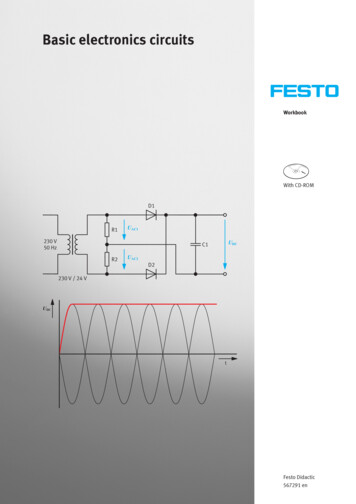
Basic electronics circuitsWorkbookWith CD-ROMD1R1UAC1230 V50 HzUDCC1R2UAC2D2230 V / 24 VUDCtFesto Didactic567291 en
Order no.Revision arl-Heinz DrükeFrank EbelAnika Kuhn, Thomas Ocker, Doris Schwarzenberger12/2011, Frank Ebel, Beatrice Huber Festo Didactic GmbH & Co. KG, D-73770 Denkendorf, Germany, 2011Internet: www.festo-didactic.come-mail: did@de.festo.comThe copying, distribution and utilization of this document as well as the communication of its contents toothers without expressed authorization is prohibited. Offenders will be held liable for the payment ofdamages. All rights reserved, in particular the right to carry out patent, utility model or ornamental designregistration.
Table of ContentsIntended use IVPrefaceVIntroduction VIIWork and safety instructions VIIITraining package – Fundamentals of electrical engineering/electronics (TP 1011) IXAllocation of learning objectives to exercises – basic electronic circuits XEquipment set XIIIAllocation of components to exercises – basic electronic circuits XVIIINotes for the teacher/trainer XXStructure of the exercises XXIComponent designations XXIContents of the CD-ROM XXIIExercises and solutionsExercise 1:Exercise 2:Exercise 3:Exercise 4:Exercise 5:Exercise 6:Exercise 7:Exercise 8:Exercise 9:Exercise 10:Examining characteristic values of transistors 3Differentiating basic transistor circuits 21Examining multistage amplifiers 39Setting up a power amplifier 57Amplifying direct voltage signals 73Generating pulse voltage and sawtooth voltage 91Setting up sine-wave generators with LC and RC elements 111Examining power pack circuits 129Becoming familiar with DC voltage converters 147Using thyristors and triacs 163Exercises and worksheetsExercise 1:Exercise 2:Exercise 3:Exercise 4:Exercise 5:Exercise 6:Exercise 7:Exercise 8:Exercise 9:Exercise 10:Examining characteristic values of transistors 3Differentiating basic transistor circuits 21Examining multistage amplifiers 39Setting up a power amplifier 57Amplifying direct voltage signals 73Generating pulse voltage and sawtooth voltage 91Setting up sine-wave generators with LC and RC elements 111Examining power pack circuits 129Becoming familiar with DC voltage converters 147Using thyristors and triacs 163 Festo Didactic GmbH & Co. KG567291III
Use for intended purposeThe training package for “Basic principles of electrical engineering/electronics” may only be used: For its intended purpose in teaching and training applications When its safety functions are in flawless conditionThe components included in the training package are designed in accordance with the latest technology aswell as recognised safety rules. However, life and limb of the user and third parties may be endangered, andthe components may be impaired, if they are used incorrectly.The learning system from Festo Didactic has been developed and produced exclusively for training andfurther education in the field of automation technology. The training companies and/or trainers must ensurethat all trainees observe the safety instructions described in this workbook.Festo Didactic hereby excludes any and all liability for damages suffered by trainees, the training companyand/or any third parties, which occur during use of the equipment sets in situations which serve anypurpose other than training and/or vocational education, unless such damages have been caused by FestoDidactic due to malicious intent or gross negligence.IV Festo Didactic GmbH & Co. KG567291
PrefaceFesto Didactic’s training system for automation and technology is geared towards various educationalbackgrounds and vocational requirements. The learning system is therefore broken down as follows: Technology-oriented training packages Mechatronics and factory automation Process automation and control technology Mobile robotics Hybrid learning factoriesThe training system for automation and technology is continuously updated and expanded in accordancewith developments in the field of education, as well as actual professional practice.The technology packages deal with various technologies including pneumatics, electro-pneumatics,hydraulics, electro-hydraulics, proportional hydraulics, programmable logic controllers, sensor technology,electrical engineering, electronics and electric drives.The modular design of the training system allows for applications which go above and beyond thelimitations of the individual training packages. For example, PLC actuation of pneumatic, hydraulic andelectric drives is possible. Festo Didactic GmbH & Co. KG567291V
All training packages feature the following elements: Hardware Media SeminarsHardwareThe hardware in the training packages is comprised of industrial components and systems that are speciallydesigned for training purposes. The components contained in the training packages are specificallydesigned and selected for the projects in the accompanying media.MediaThe media provided for the individual topics consist of a mixture of courseware and software. Thecourseware includes: Technical literature and textbooks (standard works for teaching basic knowledge) Workbooks (practical exercises with supplementary instructions and sample solutions) Lexicons, manuals and technical books (which provide technical information on groups of topics forfurther exploration) Transparencies and videos (for easy-to-follow, dynamic instruction) Posters (for presenting information in a clear-cut way)Within the software, the following programmes are available: Digital training programmes (learning content specifically designed for virtual training) Simulation software Visualisation software Software for acquiring measurement data Project engineering and design engineering software Programming software for programmable logic controllersThe teaching and learning media are available in several languages. They are intended for use in classroominstruction, but are also suitable for self-study.SeminarsA wide range of seminars covering the contents of the training packages round off the system for trainingand vocational education.Do you have suggestions or criticism regarding this manual?If so, send us an e-mail at did@de.festo.com.The authors and Festo Didactic look forward to your comments.VI Festo Didactic GmbH & Co. KG567291
IntroductionThis workbook is part of the learning system for automation and technology by Festo Didactic GmbH & Co.KG. The system provides a solid basis for practice-oriented training and continuing vocational education.The training package “Fundamentals of electrical engineering/electronics” (TP 1011) covers the followingtopics: Fundamentals of direct current technology Fundamentals of alternating current technology Fundamentals of semiconductors Basic electronic circuitsThe workbook for basic electronic circuits completes the series of workbooks for “Basic principles ofelectrical engineering/electronics”. Particular emphasis is placed on the analytical examination ofinteraction between the components already covered in the first three books on the basic principles.A laboratory workstation equipped with a fused mains power supply, two digital multimeters, a storageoscilloscope and safety laboratory cables is required for setting up and evaluating the circuits.The circuits for all 10 exercises covering basic electronic circuits are set up using the TP 1011 equipment set.Technical data for the various components (diodes, transistors, measuring devices etc.) is also available. Festo Didactic GmbH & Co. KG567291VII
Work and safety instructionsGeneral information Trainees should only work with the circuits under the supervision of a trainer. Observe specifications included in the technical data for the individual components, and in particular allsafety instructions! Malfunctions which may impair safety must not be generated in the training environment and must beeliminated immediately.Electrical components Risk of death in case of interrupted protective earth conductor!– The protective earth conductor (yellow/green) must never be interrupted, either inside or outside adevice.– The insulation of the protective earth conductor must never be damaged or removed. German trade association regulations BGV A3, “Electrical systems and equipment”, must be observed incommercial facilities. In schools and training facilities, the operation of power supply units must be responsibly monitored bytrained personnel. Caution!The capacitors in the device may still carry a charge even after it has been disconnected from all powersources. When replacing fuses, use specified fuses only with the correct current rating. Never switch the power supply unit on immediately after it has been moved from a cold room to a warmroom. Under unfavourable conditions, the condensate which forms as a result may damage the device.Leave the device switched off until it has reached room temperature. Use only extra-low voltage (max. 25 V DC) as the operating voltage for the circuits in the variousexercises. Electrical connections may only be established in the absence of voltage. Electrical connections may only be interrupted in the absence of voltage. Use only connecting cables with safety plugs for electrical connections. Always pull the safety plug when disconnecting connecting cables – never pull the cable.VIII Festo Didactic GmbH & Co. KG567291
Training package – Fundamentals of electrical engineering/electronics(TP 1011)Training package TP 1011 consists of a multitude of training materials. The subject of this part of theTP 1011 training package is basic electronic circuits. Individual components included in training packageTP 1011 may also be included in other packages.Important components of TP 1011 Permanent workstation with EduTrainer universal patch panel Component set for electrical engineering/electronics with jumper plugs and safety laboratory cables EduTrainer basic power supply unit Complete set of laboratory equipmentMediaThe courseware for training package TP 1011 consists of four workbooks. The workbooks include exercisesheets for each exercise, the solutions to each individual worksheet and a CD-ROM. A set of ready-to-useexercise sheets and worksheets is included in each workbook for all of the exercises.Data sheets for the hardware components are made available along with the training package, and on theCD-ROM.MediaWorkbooksFundamentals of direct current technologyFundamentals of alternating current technologyFundamentals of semiconductorsBasic electronic circuitsDigital training programmes WBT Electrical engineering 1 – Fundamentals of electrical engineeringWBT Electrical engineering 2 – Direct and alternating current circuitsWBT Electronics 1 – Fundamentals of semiconductor technologyWBT Electronics 2 – Integrated circuitsWBT Electrical protective measuresOverview of media for training package TP 1011Digital learning programmes available for training package TP 1011 include Electrical engineering 1,Electrical engineering 2, Electronics 1, Electronics 2 and Electrical protective measures. These programmesexplore the basic principles of electrical engineering/electronics in detail. Training content is elucidated onthe basis of practical case studies in a systematic, applications-oriented fashion.The media are offered in several languages. You can find further training materials in our catalogue and onthe Internet. Festo Didactic GmbH & Co. KG567291IX
Allocation of learning objectives to exercises – basic electronic circuitsX Exercise 1: Characteristic values of transistorsYou learn to test transistors for correct functioning.You learn to ascertain current amplification B for transistors.You become familiar with typical current amplification values for transistors.You learn to convert circuits for NPN transistors into circuits for PNP transistors.You learn to ascertain a circuit’s voltage amplification.You become familiar with the effects of operating point adjustments.You become familiar with the effects of overdriving an amplifier. Exercise 2: Basic transistor circuitsYou become familiar with the difference between an emitter follower and a common emitter circuit.You become familiar with the three basic transistor circuits.You learn to measure voltage amplification in transistor circuits.You become familiar with typical voltage amplification in basic transistor circuits.You know which basic transistor circuit causes a 180 phase shift.You know which basic transistor circuits are non-inverting.You learn to specify typical input and output resistance for the basic circuits.You learn to measure input and output resistance at amplification circuits. Exercise 3: Multistage amplifiersYou learn what a Darlington circuit is.You become familiar with complementary Darlington circuit.You learn to measure current in the nano-ampere range.You know what inverse feedback is.You learn to programme amplification gain with two resistors.You learn to generate measurement signals in the millivolt range.You learn to record an amplifier’s frequency response.You learn to ascertain an amplifier’s cut-off frequency. Festo Didactic GmbH & Co. KG567291
Exercise 4: Power amplifierYou become familiar with operating point adjustment is circuits with positive and negative operatingvoltage.You learn to recognise inverse feedback.You learn which components determine a circuit’s amplification gain GU.You learn to recognise whether a given amplifier is a power amplifier or a voltage amplifier.You learn to recognise a push-pull output stage.You learn what crossover distortion is.You learn how inverse feedback effects signal distortion.You learn to differentiate between class B operation and class AB operation of an output stage.You learn to measure an output stage’s quiescent current without an ammeter.You learn to determine an amplifier’s output power. Exercise 5: Differential and direct voltage amplifiersYou learn to recognise the typical structure of a basic, differential amplifier circuit.You learn to indirectly determine current within circuits.You become familiar with the typical characteristics of a differential amplifier.You learn to record and draw the two characteristic curves – Uout f (Uin) – of a differential amplifier.You learn the difference between differential amplification und common-mode amplification.You learn how to achieve a high common-mode rejection ratio, and where this attribute is necessary.You learn to recognise a constant current source/sink, and how to calculate constant current.You know what a comparator is.You learn to set up a twilight switch and explain its function.You learn what self-excitation is and what it does.You become familiar with the layout and typical characteristics of a direct voltage amplifier.You learn about offset and offset alignment. Exercise 6: Pulse and sawtooth generatorsYou learn to recognise the basic circuit of the classical astable multivibrator (AMV).You become familiar with the typical characteristics of an astable multivibrator.You become familiar with the characteristics of a trigger circuit.You learn to measure and calculate the trigger levels and hysteresis of a trigger circuit.You learn to convert a trigger circuit and an RC element into a square-wave generatorYou learn to measure and calculate pulse data for various square-wave generators.You learn what pulse-width modulation is (PWM) and how it is used.You become familiar with the characteristics of a monostable trigger circuit.You learn to measure the capacitance of capacitors.You learn to dimension the time-determining elements of various pulse circuits.You learn how a unijunction transistor (UJT) works and how to test it.You learn to convert curved sawtooth voltages into linearly rising sawtooth voltages. Festo Didactic GmbH & Co. KG567291XI
XIIExercise 7: Sine-wave generatorsYou learn the typical characteristics of an LC resonant circuit.You learn to measure and calculate the resonant frequency of a resonant circuit.You learn to recognise a resonant circuit with three-point connection.You learn to determine the coupling coefficient of a frequency determining circuit section.You learn to set up and commission LC oscillators.You learn how to determine the inductance of unknown coils with the help of an oscillator.You learn the working principle of inductive proximity sensors.You learn how to set up and commission a metal detector.You become familiar with the basic circuit and the characteristics of a Wien element.You become familiar with the layout of an RC sine-wave generator with Wien element.You become familiar with the problem of amplification settings for RC generators.Exercise 8: Power pack circuitsYou learn the functions of the power pack in electronic devices.You become familiar with the most important rectifier circuits in power supply units.You learn the meanings of the terms half-wave rectifier und full-wave rectifier.You learn where the charging capacitor is located within a circuit.You learn to determine internal resistance or output resistance of voltage sources.You become familiar with the term “reference voltage”.You learn how an electronic voltage regulator works.You learn how to calculate the output voltage of voltage regulating circuits.You become familiar with the task and the operating function of the current limiter in power supplyunits.Exercise 9: DC voltage convertersYou learn how current in a coil responds when direct voltage is applied.You learn how voltage at a coil responds when supply power is switched off.You learn to measure current characteristics in a coil indirectly, and display them at an oscilloscope.You learn to use a PNP transistor as an electronic switch for positive operating voltage.You learn to convert positive direct voltage into negative direct voltage.You can generate a large direct voltage from a small one.You learn to set up a blocking oscillator consisting of a transistor and a transformer.You know what a charge pump is.You learn how to stabilise output voltage at voltage transformers. Festo Didactic GmbH & Co. KG567291
Exercise 10: Thyristors and triacsYou learn the difference between the performance of a thyristor and that of a transistor.You become familiar with the term “silicon controlled rectifier” (SCR).You learn the conditions under which a thyristor is “ignited”.You learn when a conducting thyristor is once again rendered non-conductive.You learn to test a thyristor for correct functioning with the help of simple means.You learn the difference between a thyristor and a triac.You learn how to activate thyristors in a potential-free or isolated manner.You learn how to switch direct current and alternating current with thyristors.You become familiar with the function of a semiconductor relay.You become familiar with the function of a phase-fired controller.Equipment setThe workbook for fundamentals of electrical engineering/electronics imparts knowledge regarding layout,function and performance of amplifier circuits, power pack circuits, flip-flops and circuits used in powerelectronics.The equipment set for fundamentals of electrical engineering/electronics (TP 1011) contains all thecomponents required to achieve the specified learning objectives. Two digital multimeters, a digital storageoscilloscope and safety laboratory cables are also required for setting up and evaluating functional circuits.Equipment set – Fundamentals of electrical engineering/electronics, order no. 571780ComponentOrder no.QuantityEduTrainer basic power supply unit5673211EduTrainer universal patch panel5673221Component set for electrical engineering/electronics5673061Safety jumper plugs, 19 mm, grey-black5718091 Festo Didactic GmbH & Co. KG567291XIII
Overview of the component set for electrical engineering/electronics, order no. 567306ComponentXIVQuantityResistor, 10 Ω / 2 W1Resistor, 22 Ω / 2 W2Resistor, 33 Ω / 2 W1Resistor, 100 Ω / 2 W2Resistor, 220 Ω / 2 W1Resistor, 330 Ω / 2 W1Resistor, 470 Ω / 2 W2Resistor, 680 Ω / 2 W1Resistor, 1 kΩ / 2 W3Resistor, 2.2 kΩ / 2 W2Resistor, 4.7 kΩ / 2 W2Resistor, 10 kΩ / 2 W3Resistor, 22 kΩ / 2 W3Resistor, 47 kΩ / 2 W2Resistor, 100 kΩ / 2 W2Resistor, 1 MΩ / 2 W1Potentiometer, 1 kΩ / 0.5 W1Potentiometer, 10 kΩ / 0.5 W1Thermistor (NTC), 4.7 kΩ / 0.45 W1Light-dependent resistor (LDR), 100 V / 0.2 W1Voltage-dependent resistor (VDR), 14 V / 0.05 W1Capacitor, 100 pF / 100 V1Capacitor, 10 nF / 100 V2Capacitor, 47 nF / 100 V1Capacitor, 0.1 μF / 100 V2Capacitor, 0.22 μF / 100 V1Capacitor, 0.47 μF / 100 V2Capacitor, 1.0 μF / 100 V2Capacitor, 10 μF / 250 V, polarised2Capacitor, 100 μF / 63 V, polarised1Capacitor, 470 μF / 50 V, polarised1 Festo Didactic GmbH & Co. KG567291
ComponentQuantityCoil, 100 mH/50 mA1Diode, AA1181Diode, 1N40076Zener diode, ZPD 3.31Zener diode, ZPD 101Diac, 33 V / 1 mA1NPN transistor, BC140, 40 V / 1 A2NPN transistor, BC547, 50 V / 100 mA1PNP transistor, BC160, 40 V / 1 A1P-channel JFET transistor, 2N3820, 20 V / 10 mA1N-channel JFET transistor, 2N3819, 25 V / 50 mA1Unijunction transistor, 2N2647, 35 V / 50 mA1P-channel MOSFET transistor, BS250, 60 V / 180 mA1Thyristor, TIC 106, 400 V / 5 A1Triac, TIC206, 400 V / 4 A1Transformer coil, N 2001Transformer coil, N 6002Iron transformer core with holder1Signal lamp, 12 V / 62 mA1Light-emitting diode (LED), 20 mA, blue1Light-emitting diode (LED), 20 mA, red or green1Changeover switch1 Festo Didactic GmbH & Co. KG567291XV
Graphic symbols, equipment setComponentGraphic symbolComponentGraphic symbolResistorZener diodePotentiometerDIACThermistor (NTC)NPN transistorLight-dependent resistor (LDR)PNP transistorVoltage-dependent resistorP-channel JFET transistor(VDR)UCapacitorXVIN-channel JFET transistor Festo Didactic GmbH & Co. KG567291
ComponentGraphic symbolComponentCapacitor, polarisedUnijunction transistorCoilP-channel MOSFET transistorDiodeThyristorTriacBlue LEDTransformer coilRed or green LEDSignal lampChangeover switch Festo Didactic GmbH & Co. KG567291Graphic symbolXVII
Allocation of components to exercises – basic electronic circuitsExercise123456789102214424ComponentDiode, 1N4007Electrolytic capacitor, 10 μF122Electrolytic capacitor, 100 μFElectrolytic capacitor, 220 μF111111111Electrolytic capacitor, 470 μF1JFET transistor, 2N38191JFET transistor, 2N38201Capacitor, 1 nF1Capacitor, 10 nF12Capacitor, 47 nF21Capacitor, 0.1 μF1Capacitor, 0.22 μF1122111Capacitor, 0.47 μF1Capacitor, 1 μF1Light-emitting diode, 20 mA, blue111111Light-emitting diode, 20 mA, red or green111111Coil, 100 mH/50 mA1111111Thyristor, TIC1061Triac, TIC2061Transformer coil, N 200Transformer coil, N 6001Iron transformer core with holderXVIII11Signal lamp, 12 V / 62 mAPotentiometer, 10 kΩ1Transistor, BC1401Transistor, BC1601Transistor, BC54711111111112222222111111111111111Unijunction transistor, 2N264711Changeover switch11 Festo Didactic GmbH & Co. KG567291
Exercise12345678910ComponentResistor, 10 Ω11Resistor, 33 Ω1Resistor, 100 Ω112111111Resistor, 220 Ω1Resistor, 330 Ω1Resistor, 470 Ω11Resistor, 680 Ω1Resistor, 1 kΩ2Resistor, 2.2 kΩ2511Resistor, 4.7 kΩ113221252321114243212222Resistor, 22 kΩ211222Resistor, 10 kΩ2121634423Resistor, 47 kΩ1111132223Resistor, 100 kΩ1142112111Resistor, 1 MΩ1Light-dependent resistor (LDR)1Zener diode, ZPD 10 Festo Didactic GmbH & Co. KG1567291XIX
Notes for the teacher/trainerLearning objectivesThe basic learning goal of this workbook is the setup and analysis of selected basic circuits. Amongst others,the circuits include power pack circuits, amplifier circuits, flip-flops and circuits used in power electronics.This direct interplay of theory and practice ensures fast progress and long-lasting learning. Concrete,individual learning objectives are assigned to each exercise.Required timeThe time required for working through the exercises depends on the learner’s previous knowledge of thesubject matter. Roughly 1 to 1½ hours should be scheduled for each exercise.Equipment set componentsThe workbook and the equipment set are designed to be used together. All 10 exercises can be completedusing components from one TP 1011 equipment set.StandardsThe following standards are applied in this workbook:EN 60617-2 to EN 60617-8Graphic symbols for diagramsEN 81346-2Industrial systems, installations and equipment and industrial products;structuring principles and reference designationsIEC 60364-1Low-voltage electrical installations – Fundamental principles,(DIN VDE 0100-100)Assessment of general characteristics, definitionsIEC 60346-4-41Low-voltage electrical installations – Protective measures –(DIN VDE 0100-410)Protection against electric shockIdentification in the workbookSolutions and supplements in graphics or diagrams appear in red.Exception: Information and evaluations regarding current are always in red; information and evaluationsregarding voltage are always in blue.Identification in the worksheetsTexts which require completion are identified with a grid or grey table cells.Graphics and diagrams which require completion include a grid.XX Festo Didactic GmbH & Co. KG567291
SolutionsThe solutions specified in this workbook result from test measurements. The results of your measurementsmay vary from these data.Learning topicsFor the vocation of electrician, the learning topic “basic electronic circuits” is assigned to field of learning 1of the vocational school.Structure of the exercisesAll 10 exercises have the same structure and are broken down into: Title Learning objectives Problem description Circuit or positional sketch Project assignment Work aids WorksheetsThe workbook contains the solutions for all exercises.Component designationsThe components in the circuit diagrams are identified in accordance with EN 81346-2. Letters are assignedas appropriate to each component. Multiple components of the same type within a single circuit arenumbered.Resistors:Capacitors:Indicators:R, R1, R2, .C, C1, C2, P, P1, P2, .NoteIf resistors and capacitors are interpreted as physical variables, the letter identifying them is initalics (symbols). If digits are required for numbering, they are treated as indices and appear assubscript. Festo Didactic GmbH & Co. KG567291XXI
Contents of the CD-ROMThe workbook is included on the CD-ROM as a PDF file. The CD-ROM also provides you with additionalmedia.The CD-ROM contains the following folders: Operating instructions Illustrations Presentations Product informationOperating instructionsOperating instructions are provided for various components included in the training package. Theseinstructions are helpful when using and commissioning the components.IllustrationsPhotos and graphics of components and industrial applications are made available. These can be used toillustrate individual tasks or to supplement project presentations.PresentationsThis directory contains short presentations for the circuits covered by the training package. These can beused, for example, to create project presentations.Product informationContains product information from the manufacturers of selected components. The representations anddescriptions of the components in this format are intended to show how they would appear in an industrialcatalogue. Additional information regarding the components is also included.XXII Festo Didactic GmbH & Co. KG567291
Table of contentsExercises and solutionsExercise 1:Exercise 2:Exercise 3:Exercise 4:Exercise 5:Exercise 6:Exercise 7:Exercise 8:Exercise 9:Exercise 10:Examining characteristic values of transistors 3Differentiating basic transistor circuits 21Examining multistage amplifiers 39Setting up a power amplifier 57Amplifying direct voltage signals 73Generating pulse voltage and sawtooth voltage 91Setting up sine-wave generators with LC and RC elements 111Examining power pack circuits 129Becoming familiar with DC voltage converters 147Using thyrist
The circuits for all 10 exercises covering basic electronic circuits are set up using the TP 1011 equipment set. Technical data for the various components (diodes, transistors, measuring devices etc.) is also available.File Size: 1MBPage Count: 62