Transcription
Introduction To Model-BasedSystem Engineering (MBSE) andSysMLPresented at the Delaware Valley INCOSE Chapter MeetingJuly 30, 2015Laura E. HartLockheed Martin, IS&GSLaura.E.Hart@lmco.com610-354-6529Copyright 2015 Lockheed Martin Corporation 1
Topics MBE/MBSE Terminology and OverviewSysML OverviewObject Oriented SE Methodology (OOSEM)Modeling Tools and the Environment2
Terminology Model:– A simplified version of a concept, phenomenon, relationship,structure or system– A graphical, mathematical or physical representation– An abstraction of reality by eliminating unnecessary components– The objectives of a model include; to facilitate understanding to aid in decision making, examine 'what if' scenarios to explain, control, and predict events“Model-Based Engineering (MBE): An approach to engineering that uses models asan integral part of the technical baseline that includes the requirements, analysis,design, implementation, and verification of a capability, system, and/or productthroughout the acquisition life cycle.”Final Report, Model-Based Engineering Subcommittee, NDIA, Feb. 20113
Terminology MBSE: Model Based Systems Engineering– Those aspects of MBE specifically associated with SE– includes behavioral analysis, system architecture, requirementtraceability, performance analysis, simulation, test, etc.“Model-based systems engineering (MBSE) is the formalized application ofmodeling to support system requirements, design, analysis, verification andvalidation activities beginning in the conceptual design phase and continuingthroughout development and later life cycle phases.”INCOSE SE Vision 2020 (INCOSE-TP-2004-004-02, Sep 2007)4
MBSE FocusLife Cycle Support Broad in scope– Includes multiple modelingdomains across life cyclefrom SOS to component Results in quality/productivityimprovements & lower risk– Rigor and precision– Communications amongdevelopment team and customer– Management of complexityVertical Integration Formalizes the practice ofsystems development through the useof modelsMBSE5
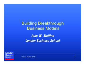
Model-Based Engineering:What, Why and How? Digital models have beencommon in engineering sincethe late 1960s but today’sfocus on Model-basedEngineering goes beyond theuse of disparate models Model-based Engineeringmoves the record of authorityfrom documents to digitalmodels including M-CAD, ECAD, SysML and UMLmanaged in a data richenvironment Shifting to model-basedenables engineering teams tomore readily understanddesign change impacts,communicate design intentand analyze a system designbefore it is builtDocument-CentricModel-Centric6
Model-Based Engineering:What, Why and How? Model-based SystemsEngineering provides amechanisms for drivingmore systems engineeringdepth without increasingcosts Data-centric specificationsenable automation andoptimization, allowing SEsto focus on value addedtasks and ensure abalanced approach is taken Unprecedented levels ofsystems understanding canbe achieved throughintegrated analytics, tied toa model-centric technicalbaseline.Why Model?7
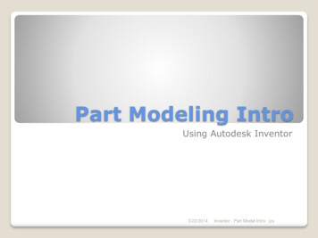
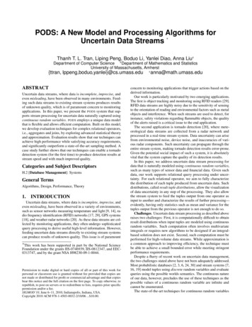
Detect Defects Earlier Operational Analysis Operational TestsAffordability Detect Defects EarlyRequirementsAnalysisSystem andArchitecture Design Integration Test andVerificationUnit TestDetailed Design System Verificationand ValidationImplementationDesign, Build, and Test Components8
Model-Based Engineering:What, Why and How? The key to a successful modelbased approach is scoping theproblem! What do you want to get outof your models? What fidelity do you need toaccomplish those goals? What are the successcriteria for the effort? Scoping and managing amodeling effort is both an artand a science Driving change in anorganization takes time andcontinuous investment9
Model Based Environment Characteristics Set of interconnected Models– Models are an abstraction of Reality– Structure, Behavior and Requirements Standard Language– Graphical Notation, Syntax, Semantics– Visual focus– Static and Dynamic Shared System Information Base10
SE Practices for Describing SystemsPastFuture Specifications Interface requirements System designATCPilotAirplaneRequest to proceedAuthorize Analysis & Trade-offInitiate power-upPower-up Report StatusTest plansDirect taxiwayInitiate TaxiExecuted anguage(SysML)Tools(Rhapsody)Moving from Document centric to Model centric11Copyright 2006 by Object Management Group.
System ModelingRequirement ModelFunctional / Behavioral ModelStartShiftAccelerateBrakePerformance ModelControl InputSystem rtiesModel Structural / Component ModelOther EngineeringAnalysis ModelsCostModelfrom OMGIntegrated System Model Must Address Multiple Aspects of a System12Copyright 2006 by Object Management Group.
Modeling Helps Produce Improved system and software––––––– Simulation and TestDocumentationValidation and VerificationImproved communications– Enhanced knowledgecapture and transfer– Training Support Increased ability to manage System Complexity Model can be viewed from multiple perspectives Traceability Supports concurrent and distributive teamsSupports impact/change analysisComplex development lifecycles Incremental, iterative, parallel Improved design quality– Decreased ambiguity– Increased precision– Supports evaluation of Consistency,Correctness & Completeness– Supports evaluation of trade space13
Stakeholders Involved in ojectManagersVendorsRegulatorsTestersfrom OMGModeling Needed to Improve Communications across all Stakeholders14Copyright 2006 by Object Management Group.
Information Base CharacteristicsDocument BasedMBSE BasedInformation- Mostly Text- Add Hoc Diagrams- Loosely coupled,repeated in multipledocuments- Visual and Textual- Constructs Defined once andre-used- Shared across Domains- Consistent notation in diagrams- Defined relationshipsInformation Views- By Document- Provides Viewpoints- Filters By Domain, ProblemSpace, etc.Measuring ChangeImpact- Spans across MultipleDocuments- Often Text Reqts. Areisolated from Structureand Behavior- Relationships definetraceability paths- Natural part of the modelingprocess- Programmatically AutomatedMeasuring Integrity Completeness, Quality& Accuracy- By manual inspection- Programmatically Automated- Animation of Spec15
The MBSE Integration Across DomainsProgramManagementProduct SupportSystem ArchitecturalModelAnalytical Models TestPlanG(s)AnalysisSpecU(s)Verification ModelsMBSEPerformance, RMA,SWaP, Cost, etc.ManufacturingMechanical &Electrical ModelsSSETSoftware ModelsQR CLR Q16
SystemArchitecture Models vs. Analytical ModelsSystem Architecture Model Emphasize how pieces fittogether into a consistentwhole Repository-based to supportcapture of inter-relationships Used to capture––––functions, behaviorstructure, components, objectsinfo flow, interfaces, portsInteractions, scenarios A vehicle to “hang” & integrateanalysis productsAnalytic Model Emphasize specific aspects ofperformance, consistent withthe Architecture Model Mathematically-based tocomputation or simulation Reduce risks thru analysis,validation and optimization of:––––MoM, MOE, MOP, KPP, TPMtiming, probability of hit/survivalreliability/availability, MTBFcost, total cost of ownership A vehicle to solve some problem ora solutionConsistency: Faithful to all known and verifyrelevantaspectsof the system at the current time17
System ModelSystem Model – A structured representationrequirements,that focuses on the overall systembehavior, structure, properties, & interconnections Requirements––What are the stakeholder goals, purposes, and success conditions for the systemSpecification of black box behavior and characteristicsBehavior––––What the system has to do to meet the requirementsTransformations of inputs to outputs (functional/activity models)State/Mode-based behavioral differences (state models)Responses to incoming requests for services (message models)Structure––The parts that exhibit the behaviorThe component hierarchy, elements, and storesProperties–The performance, physical characteristics and governing rules that constrain the structure andbehaviorInterconnections–The way the structural elements arrange and communicate to achieve the required behaviorunder the given constraints18120-18
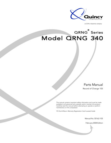
System Decomposition Process using SysMLAnalyze System Level RequirementsUC.InputSatCommsWeapon SystemWeaponForward Message fromRegional CommandReceive OrderEvaluate EngagementStart EnagementFire WeaponMonitor Weapon[Status Change]Analyze System Services[No][Correction Needed]Send Guidance CommandWeapon Intercept?Terminate EngagementCorrect CourseForward Message toRegional CmdSend Status ChangeForward Message toRegional CmdIdentify the SubsystemSatCommsWeapon SystemWeaponForward Message fromRegional CommandReceive OrderEvaluate EngagementAnalyze Subsystem Collaboration to Satisfythe System ServicesStart EnagementFire WeaponMonitor Weapon[Status Change][No][Correction Needed]Send Guidance CommandWeapon Intercept?Terminate EngagementCorrect CourseForward Message toRegional CmdSend Status ChangeForward Message toRegional CmdIncorporate AdditionalAnalysis as NeededDerive and Allocate Requirementsto SubsystemYesTrade Studies, R&D,Simulation, SpecificationReviews, etc.UC.The Subsystem shall .DerivedRequirementsContinue?NoComplete Subsystem Specs1919
Beyond Specifications: IntegratedSystems Models Model-based SystemsEngineering doesn’t endwith the creation ofspecifications and ICDs A Systems ArchitectureModel provides a “hub” fordata integration andtransformation across theproduct lifecycle Specifically of note is theability to link analysisthrough the systems modelto provide insight intoarchitectural and systemlevel decisions20
Model-based Engineering Baseline:An Integrated Data Set21
Systems Understanding and Analyticsthrough Model-based Architectures A critical task in Systems Engineering is the upfronttrade and analysis process to ensure the best valuesystem is developed to satisfy the mission need As missions become more complex, understandingall items that can impact the system performancebecomes harder Integrating high fidelity analytics through aconsistently defined systems architecture can helpprovide insight into key system characteristics notevident through traditional analysis alone Integrated tools allow engineers to analyze manymore system configurations against missionscenarios, helping to identify key drivingrequirements and lowest cost alternatives forsystems design22
Expanding base of MBSE Tool Capabilities The MBSE tools marketplacehas been expanding beyondjust graphical modeling andrequirement tools with a focuson data and model integrationPhoenix IntegrationModelCenter has beenexpanded to help bridge SysMLto multidisciplinary analysisthrough the release of theModelCenter MBSE PakWith MBSEPak, SysMLparametric models withinRhapsody or MagicDraw canbe executed, linkingrequirements to design toanalysis and backSystem Model (SysML) Architecture Requirements Execution requests Trade-Study requests Behavior ConstraintsSystems Engineering Traceability Specifications Performance Estimates Updated Design Requirement VerificationBridge gapModelCenterMechanicalAnalysisDoElectrical ManufacturingAnalysisAnalysis Validate Requirements Verify Correctness Sensitivity Analysis Risk AnalysisSoftwareDesignCostAnalysis Optimization VisualizationDomain Level Engineering23
Architecture Centric Analytics A SysML Architecture can serve as ahub for integrated analytics, capturinganalysis, analysis context,requirements and key architecturalparameters Analysis context specifies theboundaries of the analysis, parametricviews define the analysis to beperformed and requirements diagramscan capture design goals, thresholdsand driving requirements to bound thetradespace This model-centric approach provides aconsistent, managed framework foranalysis which often tends to be ad-hoc24
Integrated Modeling and AnalysisSupport for Decision Makers Decision makers will have moreinformation and options fromwhich to draw conclusions Integrated analytics models willboth increase the amount ofinformation available to decisionmakes as well as help decisionmakers make sense of theinformation Tools to explore, visualize andunderstand a complextradespace, rooted in MBSE canprovide early insight into theimpact of decisions rangingfrom technical solutions tocomplex public policiesContent Credit INCOSE Systems Engineering Vision 202525
Model-based Engineering:What, Why and How?ArchitectureCADSoftwareCostManufacturing The primary focus of mostcurrent industry efforts to movetoward a Model-basedEngineering approach focus onintegrating data through models Engineering Is Responsible ToUnderstand All Items That CouldImpact A Design And DetermineA Resolution For Those Items –an integrated end-to-endmodeling environment supportsthis role By bringing together varied butrelated models into a data rich,architecture centric environment,new levels of systemsunderstanding can be achieved Model-based SystemsEngineering forms a means toachieve integrationPerformanceElectronicsVerification26
MBE Summary What?––––––Extends beyond EngineeringCovers the entire Life CycleStandards BasedIntegrated Domains/Disciplines Data EnvironmentDoing the same SE TasksEnvironment for Automation and Validation Why? – Customers want “Cheaper, Better, Faster”– Reduce Design Time– Improve Quality– Make Complex Systems Affordable27
Topics MBE/MBSE Terminology and OverviewSysML OverviewObject Oriented SE Methodology (OOSEM)Modeling Tools and the Environment28
What is SysML? A graphical modelling language in response to the UML for SystemsEngineering RFP developed by the OMG, INCOSE, and AP233– a UML Profile that represents a subset of UML 2with extensions Supports the specification, analysis, design, verification, and validationof systems that include hardware, software, data, personnel,procedures, and facilities Supports model and data interchange via XML Metadata Interchange(XMI ) and the evolving AP233 standard (in-process)SysML is Critical Enabler for Model Driven SE29
SysML Diagram TaxonomySysML amRequirementDiagramState MachineDiagramUse CaseDiagramSame as UML 2StructureDiagramBlock DefinitionDiagramInternal BlockDiagramPackage DiagramParametricDiagramModified from UML 2New diagram type30Copyright 2006 by Object Management Group.
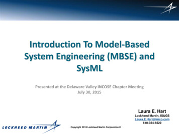
4 Pillars of SysML – ABS Examplesd ABS ActivationSequence [Sequence Diagram]Interactionstm TireTraction [State Traction1. StructuredetTrkLos()Gripping2. unctionRegainTractionmodBrkFrc(traction signal:boolean)definitionuse3. RequirementsmodBrkFrc()sendAck()4. Parametric31Copyright 2006 -2008 by Object Management Group.
Block Definition and UsageInternal Block DiagramBlock Definition Diagrambdd [package] VehicleStructure [ABS-Block Definition m1«block»BrakeModulatoribd [block] Anti-LockController[Internal Block ModulatorFrom OMGFrom OMGDefinition– Block is a definition/type– Captures properties, etc.– Reused in multiple contextsUsage Part is the usage in a particularcontext Typed by a block Also known as a role32
Parametrics -Constraint Definition and Usagebdd [package] WeightConstraints«constraintblock»Ship Weight ight{wt Σwi eight{result (w 2kTonne)}parametersw:Tonneresult: Booleanpar [Block] Ship Weight Analysis«usage»«usage»tw: TotalWeightwtwmw: MaxWeight{result (w 2k Tonne) }{wt .weight33
Cross-Connecting Model Elements1. Structure2. Behavioribd [block] Anti-LockControllerAnti-LockController[Internal BlockBlock anceibd [block] Anti-LockController[Internal Block ity»DetectLosd1:TractionOfTractionOf le: Percentagesatisfyreq [package] VehicleSpecifications[Requirements Diagram - Braking Requirements]parpar [ constraintBlock ]] StraightLineVehicleDynamics [ [ Parametric Diagramm]]par [ constraintBlock ] StraightLineVehicleDynamics [ Parametric Diagram ]Vehicle SystemSpecificationBraking nce«requirement»Anti-LockPerformanceid “102”text ”The vehicle shall stopfrom 60 mph within 150 fton a clean dry surface.”id ”337"text ”Braking subsystemshall prevent wheel lockupunder all braking conditions.”v . chassistf: . tiretl: .Friction cevbf. :brake . abs . m 1 .DutyCycle :v . brake . rotor .m:BrakingForce :f:: BrakingForceEquation[f ( tf*bf )*(tf1:- tl)] tl:bf:: BrakingForceEquation[f ( tf*bf )*(1 - tl)]F:a:F:v:x:: DistanceEquationDistanceEquation[v dx /dt]: AccelerationEquation[F ma ] m:f:v:: DistanceEquation[v dx /dt]v . Weight :a : : AccelerationEquation[F ma ]: VelocityEquationa:[a dv /dt] a :v:v:: VelocityEquation[a dv /dt]«deriveReqt»«deriveReqt»x:3. Requirements4. Parametricsv . Position :Copyright 2006 by Object Management Group.34c
Topics MBE/MBSE Terminology and OverviewSysML OverviewObject Oriented SE Methodology (OOSEM)Modeling Tools and the Environment35
OOSEM Model-Based SE Methodology Traditional top-down Scenario driven SE approach usingSysML to facilitate:– Capture and analysis of requirements and design information tospecify complex systems– Integration with OO Software development, hardware developmentand test processes– Flexibility to accommodate changing requirements and designevolution SE method that leverages object-oriented (OO) conceptssuch as:––––Blocks, value properties and ionUse cases Uses OO concepts however applied differently for SE vs. SW36
OOSEMTypical Systems Req’ts & Design Activities IPT Setup Model SetupMajor SE Development Activities Causal analysis Mission use cases/scenarios Enterprise model System use cases/scenarios Elaborated context Req’ts diagram6.CaptureDomain &Assumptions Domain Models Vocabulary Justification Models7.Optimize &EvaluateAlternatives Logical decomposition Logical scenarios Logical subsystems Parametric Diag Trade studyCommon Sub-activities10.Validate &VerifySystem Node diagram HW, SW, Data arch System deployment Test system Test cases8.ReuseOpportunityAnalysis ReusableAsset Repository COTS/GOTS9.Trace ReqtandAllocations Req’ts diagram Tables37
Topics MBE/MBSE Terminology and OverviewSysML OverviewObject Oriented SE Methodology (OOSEM)Modeling Tools and the Environment38
A modeling tool - Rhapsody Example The Architecture model in Rhapsody providesdynamic database in which to store system designinformation A given model object, such as a block, maintains it’scharacteristics throughout the model, on everydiagram in which it appears Rhapsody provides a consistent design model that isalso tied to requirements Rhapsody is one of many UML/SysML tools39
Rhapsody ViewBrowserDrawingWindow40
Typical Tool EnvironmentReq MgmtDOORSGatewayAnalysisIntegrationModel CenterReliabilityAnalysisCostAnalysisSoS , RPEorDocGenSW DesignRhapsodyPerformanceAnalysis41
How to Transition & Sustain A PracticeDeveloping SelfSufficiency isKey toTransitioning aPracticeCodifySupportOffer NecessaryTraining &Provide “Reachback” SupportDrive AdoptionThroughPrograms &Capture PilotsInfuseInfusing MBE into Lockheed Martin’sEngineering CultureBuild A Base ofPractitioners,Experts &Champions42
Laura E. HartLockheed Martin, IS&GSLaura.E.Hart@lmco.com610-354-652943
Jul 30, 2015 · 4 Terminology MBSE: Model Based Systems Engineering – Those aspects of MBE specific