Transcription
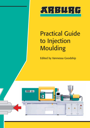
Morgan-Press Injection MolderStandard Operating ProcedureMorgan Industries, Inc.Model G-100T
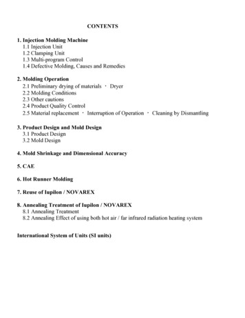
Table of ContentsIntroduction .11 Equipment Setup .22 Pneumatics.32.1 Introduction.32.2 Pneumatic Hookup .32.3 Pneumatic Controls .52.3.1Clamp System .62.3.2Injection System .93 Temperature Control .123.1 Introduction.123.2 Operational Procedures.134 Manual Operation .154.1 Purging the Morgan-Press.154.1.1Purging Materials .154.1.2How to Purge .155 Shutdown.175.1 Shutdown without Purge.175.2 Shutdown with Purge.176 Maintenance .186.1 Parts Listing.187 Troubleshooting.22Appendix .23Pneumatic System .23Pilot Valve .24Flow Control Valve.25
IntroductionThe Morgan-Press, Model G-100T, is an injection molder designed for practical and economicalmanufacturing of thermoplastic parts in quantities required for prototyping and low-volume production.It is primarily used for encapsulation, engineering prototypes, medical/dental devices, and marketingsamples. The Morgan-Press is an ideal molder because it is easy to change molds and materials tomake different parts. It is also capable of processing a full range of thermoplastic materials.The Model G-100T Morgan-Press Injection Molder has the following specifications: 0 – 800 F (0 – 430 C) temperature control range6 cu. in. (4 oz.) maximum single shot20 ton maximum clamping force (toggle)12,000 psi maximum injection pressureUtilities required:o Electrical: 120 volts ACo Compressed air: 200 psi (max.)The operating instructions and instructional video should be carefully reviewed prior to operating theMorgan-Press. Included in the manual are the equipment setup, pneumatics of the mold injector,manual operating instructions, shutdown, and maintenance.Caution: Always exercise caution and use proper protective equipment when operating the MorganPress.1
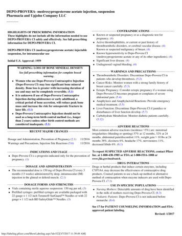
1 Equipment SetupBelow is a diagram of the equipment set up for the Morgan-Press Model G-100T.Pilot Valve connected toSupplied AirTemperature ControlSystemRam CylinderCoverPressure Gauges for Clampand InjectionBarrel TemperatureControllerNozzle TemperatureControllerMaterial Loading ChuteTable Guard withClear ShieldsBarrel CylinderUpper PlateNozzleStanchion PostsMoldTable PlateTemperature Data ChartToggle Clamp MechanismClamp Control Valve withInterlock (Orange knob)Injection Control Valve with Interlock(Black knob)Ram Power ReturnClamp Pressure Selector(Orange knurled knob)Injection Pressure Selector (Blackknurled knob)Cycle-TimerSelector2
2 Pneumatics2.1 IntroductionThe pneumatic system is used to operate the clamp system and the injection system. The air supplyfor the pneumatic system should be from a compressed air source. Line pressures up to 200 psi canbe used safely. The minimum supplied air pressure for proper operation is 100 psi. At low pressuresthe machine will still function, however, the maximum clamp force and maximum injection pressureswill be lower accordingly. When operating at higher temperatures and with more viscous materials,higher air pressure should be used.The minimum air flow for proper operation is 1 cubic feet per minute (cfm). Inadequate air flow willresult in reduced injection speed and pressure recovery time. If short shots or poorly filled parts areobserved, the air flow is too low.2.2 Pneumatic HookupMake sure the safety valve on the air supply isturned to the closed positionOpen the compressed air valve slightly3
Pneumatic Hookup (cont’d)Adjust valve so that the pressure is about 200psiOpen the safety valve to allow the air to flowthrough the molderAdjust the middle gauge valve (not pictured) toensure a pressure of about 200 psi is flowingthrough the system.Completely open the flow control valve tomaximum flow.4
2.3 Pneumatic ControlsThe pneumatic controls are located at the base of the machine. The two orange knobs control theclamp system; the two black knobs and the silver knob control the injection system.The Clamp Pressure Gauge and Injection Pressure Gauge are located at the top panel of the molder.Clamp Pressure GaugeInjection Pressure GaugeThe Ram Return Valve is located on the right side of molder base.5
2.3.1 Clamp SystemBelow are the two knobs that control the Clamp System. The Clamp Control Valve controls the raisingand lowering of the Table Plate. The Clamp Pressure Selector Valve regulates the air pressure to theClamp Control Valve. A maximum of 20 tons of clamp force is exerted at 200 psi air pressure.Clamp Control ValveClamp Pressure Selector) When clamping at 10 tons or greater, the Upper Plate assembly must be used.Excessive clamp force against the nozzle will cause damage to top casting.Step 1: Set the Clamp PressureRotate the Clamp Pressure Selector- clockwise: increase- counterclockwise: decreasedecreaseincreaseCheck that the clamp pressure is set to thedesired pressure on the Clamp Pressure Gauge6
) The Table Guard must be locked down before the Table Plate can be moved.Step 2: Raise the Table PlateOn the Clamp Control Valve, move the interlockupwardWhile holding the interlock up, push the orangeknob in until the table plate is at the desired heightRelease the interlock to maintain the table plate atthe desired height7
Step 3: Lower the Table PlateOn the Clamp Control Valve, move the interlockupwardWhile holding the interlock up, pull the orangeknob in until the table plate is lowered to thedesired heightRelease the interlock to maintain the table plate atthe desired height8
2.3.2 Injection SystemBelow are the two knobs that control the Injection System. The Injection Control Valve controls theraising and lowering of piston. The Injection Pressure Selector Valve regulates the air pressure to theInjection Control Valve. The operating range for the injection pressure is from 6-8 x 10 psi.Injection Control ValveInjection Pressure SelectorStep 1: Set the Injection PressureRotate the Injection Pressure Selector- clockwise: increase- counterclockwise: decreasedecreaseincreaseCheck that the injection pressure is set to thedesired pressure on the Injection Pressure Gauge9
) The Table Guard must be locked down before the material can be injected.Step 2: Inject PolymerOn the Injection Control Valve, move the interlockupwardWhile holding the interlock up, push the blackknob inIn the Material Loading Chute, watch as the RamRod pushes the plastic down through the barrelRelease the black knob when the Ram Rod iscompletely depressedRelease the interlock10
Step 3: Return the Ram RodPush the Ram Return Valve intermittently until theend of the Ram Rod is visible in the MaterialLoading Chute11
3 Temperature Control3.1 IntroductionTemperature can be controlled with three heaters at 3 different locations on the Morgan Press:Barrel Temperature ControllerNozzle Temperature ControllerHot Plate Temperature ControllerThe Barrel heater initially melts the plastic, while the nozzle and Hot Plate control polymertemperature during the molding process. The Barrel and Nozzle Temperature Controllers, with rangesbetween 0 to 800 F, are located on a separate electrical cabinet on the left side of the Morgan Press.A set point temperature may be set by depressing the controller knobs and adjusting the temperaturevalue. A signal light near the control knobs periodically turn on when electrical current is runningthrough the system to raise the temperature. When the light is off, the set point has been reached.The hot plate temperature, which controls the temperature of the mold, has its own setting located onthe front of the plate. A signal light on the hot plate will turn on when it is in use.A guideline of appropriate temperatures for different materials can be seen on the chart placed on thebottom front of the Morgan Press. As a rule of thumb, use the minimum temperature at which thematerial will flow successfully into the mold. The barrel temperature setting will usually be 20 to 50 Fbelow the nozzle setting.)These temperatures are simply guidelines. Refer to information given by the material’smanufacturer before processing any thermoplastic.)Thetemperature is probably too high if material drooling from the nozzle appears discolored,contains gas air bubbles, or emits fumes.)The material is probably too low if it does not drool from the nozzle or does not appear to be in afluid state during extrusion.Caution:PROLONGED HEATING MAY CAUSE ADVERSE PHYSICAL EFFECTSDIFFERENT MATERIALS. MAINTAIN A CONSISTENT MOLDING CYCLE.FORAVOID BODILY CONTACT WITH MOLTEN MATERIAL AND HEATED SURFACES.12
3.2 Operational ProceduresBefore You BeginOnce Morgan Press is plugged in and turned on, the temperature controls for the barrel and nozzle,located on the electrical cabinet, automatically turn on.Determine the proper temperatures needed for your material. Use the temperature chart ormanufacturer information. Tests may also be performed to determine optimum temperatures toproperly melt the material.13
Step 1: Setting the Barrel and Nozzle TemperaturesDepress and turn the temperature control knobs forthe barrel and nozzle until desired temperature setpoints are reachedStep 2: Setting the Hot Plate TemperatureSituate mold (and spool, if necessary) appropriatelyon top of the hot plate.Plug in Hot Plate, and set temperature to desired setpointWait until the hot plate is given enough time to reach the desired temperature and the set points arereached on the barrel and nozzle temperature controllers (signal light off).14
4 Manual Operation4.1 Purging the Morgan-PressThe Morgan-Press should be purged of residual polymer prior to use which will:1. Cleanse the barrel of polymer with contaminants, impurities, or degradation2. Remove corrosive or abrasive materials which may attack the steel if left in the barrel cylinder forextended periods3. Facilitate changing/cleaning of the nozzle4.1.1 Purging MaterialsUsually, an inert thermoplastic is used for purging, such as natural grade polyethylene orpolypropylene. Since it is readily available, low-density polyethylene (LDPE) should be used.4.1.2 How to PurgeThe most common way of purging the Morgan-Press is to freely extrude the residual polymer out ofthe Barrel. The Barrel is loaded with the desired purging material and repeatedly purged until theextrusion is satisfactory. Since LDPE is recommended for use in purging the barrel, purging iscomplete when the polymer exiting the nozzle is completely clean (clear while hot).A purging mold, created by Matt Cline, is used for purging. This ensures that the nozzle safetyinterlock is satisfied.The following steps explain how to purge the Morgan-Press:(see instructional video for further explanation)1. Place the purging mold on the Table Plateand make sure that it is properly centered2. Close the Table Guard15
3. Adjust the height of the Table Plate untilthe purging mold is flush with the nozzle4. Adjust the temperature for the Barrel andthe nozzle to the proper moldingtemperatures5. Add the polyethylene to the MaterialLoading Chute and fill the barrel until it isfull6. Remove excess polyethylene and closethe Gate7. Adjust the injection pressure to 7 x 10 psiusing the Injection Pressure Selector8. Inject the polyethylene through the purgingmold until no more polymer comes out(see Section 2.3.2)9. To return the Ram Rod, press the RamReturn Valve on the side of the molderintermittently until the end of the Ram Rodis visible in the Material Loading Chute10. Repeat until the polymer leaving thenozzle is clean) Place aluminum foil wrapped cylinders under the purging mold for easy clean-up.) Injection will not be possible until the Chute Gate is securely closed to satisfy safety interlock.16
5 ShutdownWhen the machine is no longer in use, follow the appropriate shutdown procedures below:5.1 Shutdown without Purge1. Switch off Temperature Controls and disconnect the electrical power cord2. Check that the Ram Piston is above the Barrel3. Turn the Clamp, Ram, and Injection Speed Control regulators off (check that pressure gaugesread zero pressure)4. Disconnect the air line or turn off the regulator that is supplying the unit5.2 Shutdown with Purge1. Turn the temperature controllers off or to the proper settings for the material that is used forpurging2. Remove mold from the machine (Follow instructions for purging located in section 3.1)3. When purging is complete, perform steps 1 through 4 in section 4.1) Not all applications require purging during the shutdown procedure.) Polycarbonate and ABS should be purged because they will leave a brown film on the barrel wall.)Vinyl polymers and copolymers (PVC) should always be purged because they are very corrosive.)Thermoplastic left in a barrel during shutdown and re-plasticized will degrade to some extent.17
6 MaintenanceThe Morgan Press requires very little regular maintenance. However, it is recommended that thefollowing procedures be adopted in maintaining the machine:1. Stanchion posts should be wiped clean and lightly oiled regularly.2. Put oil in the holes provided on the thrust and pivot arms of toggle mechanism under the tableon weekly basis or when dry.3. Keep dirt, granules, and chips out of the toggle area and off the table platen.4. Grease the table gears every six months.5. Keep the Ram Shaft clean of excess material constantly.6. Keep work are neat and clean.7. Inspect moveable parts for signs of wear.6.1 Parts ListingIn the event of a malfunctioning part, locate the part from the list below to find the manufacturer so areplacement can be ordered.PART NAMEMANUFACTURERBASE CASTING ASSEMBLYToggle Base CastingLower PanelControl Valve Drop Bar (2)Clamp Air RegulatorRam Air RegulatorClamp Control ValveRam Control ValveTimer ValveRam Return ValveClam Control Valve Muffler (2)Injection Control Valve MufflerReservoir CoverReservoir GasketMorganMorganMorganWatts #R-113-02-DPWatts #R-113-02-DPLexair #M384-0602Lexair #M382-1306Watson #180-N-PMLexair #M382-0601Allied Witan #C28Allied Witan #CP28MorganMorganTABLE ASSEMBLYTable PlatenTable GuardLexan Shield (4)Post Slider, Table Guard (8)Actuator PinTable Actuator, Interlock ValveElevating ShaftElevating GearTemperature Data LabelUp/Down Label3/8" Allen Key with molded handleMorganMorganMorganMorganMorganAir & Hydraulics #321004MorganBoston Gear #L-152-BY-PMorganMorganMorgan18
MOUNT PLATE ASSEMBLYMount PlateShroudUpper PanelClamp Pressure GaugeRam Pressure GageRam Actuator Interlock ValveChute CoverChute GuardSpring Clip, Table GuardMorganMorganMorganU.S. Gauge #102030U.S. Gauge #102030Air & Hydraulics #321204MorganMorganSeastrom #4521-16-50-2CTEMPERATURE CONTROLLER CABINETCabinet HousingCabinet DoorMounting BracketNozzle Temperature ControlBarrel Temperature ControlElectric CordStrain ReliefTerminal StripRocker SwitchMorganMorganMorganWatlow Series 100 standard orWatlow Series 808 optionalMorganL-51 ElectrolineKulka #600-10Carlingswitch #LTILA54-6S-WH-RC-NBLTOGGLE CLAMP MECHANISMBase Plate Assembly (All welded)Base PlateSide Plate (2)Angle Bracket (2)Side Pivot Lug (2)Center Pivot LugMorganMorganMorganMorganMorganCylinder AssemblyCylinderCylinder Back CoverCylinder Over Retainer BracketCylinder PistonCylinder Drive ShaftCylinder Piston O-RingBack Cover O-Ring SealBack Shaft O-Ring (2)Cylinder Pivot Dowel Pin (2)MorganMorganMorganMorganMorganParco #568-429 Buna-NParco #568-162 Buna-NParco #568-214 Buna-NSPS Unbrako 5/8" x 1 3/4"19
Thrust Shaft AssemblyThreaded ShaftShaft Sleeve (Welded) with:Steel BallBall RetainerBevel GearBall SocketRetainer NutMorganMorgan1 1/2" Steel BallMorganBoston Gear #L-152-BY-GMorganMorgan (1 1/4" - 12 nut)Connecting SystemConnecting Arm (2)Connecting Arm Dowel Pin (2)Shock Absorber Pad (2)Pivot ShaftMorganSPS Unbrako 5/8" x 4"MorganMorganTIE BAR ASSEMBLYStanchion Post (4)Stanchion Nut (8)Stanchion Washer (8)MorganMorganMorganUPPER PLATEN ASSEMBLYTop PlateSide Legs (2)Side, Lower box (2)Front/Back, Lower BoxBottom PlateMorganMorganMorganMorganMorganBARREL ASSEMBLYBarrel AssemblyFlangeFlange Spacer (3)Barrel Insulation CollarBarrel Heater BandNozzle Heater BandThermocouple Bayonet Adapter (2)Thermocouple (2)Barrel Heat Guard/InsulationSilicon Bolt Spacer (3)Metal Bolt Spacer (3)Barrel Bolt (3)NozzleMorganMorganMorganMorganGlenn #3066 S1Y-36"Glenn #2424 S1Y-36"Gordon #TH298-1Gordon #1598-42-4MorganMorganMorgan3/8-16 x 5" Soc Hd Cap ScrewMorgan20
TABLE ASSEMBLYRam CylinderRam Cylinder CoverRam Cylinder PistonRam ShaftBarrel PistonRam Cylinder Piston O-RingRam Shaft O-Ring (2)Ram Return SpringRam Cylinder GasketQuick Exhaust ValveQuick Exhaust Valve MufflerMorganMorganMorganMorganMorganParco #568-443 Buna NParco #568-117 (Viton)MorganMorganHannifin #OR-25Allied Witan #M0221
7 TroubleshootingDefectMold not full (short shot)Mold halves separate(part flashed at partingline)Part discoloredPossible CausesCorrective Action1. Material too cold1. Raise barrel and nozzle zone2. Mold too coldtemperatures3. Insufficient cavity venting of2. Apply heat to moldmold3. Rework mold to allow more4. Injection pressure too lowventing5. Time cycle too short4. Raise injection pressure6. Gates and/or runners too small 5. Increase injection cycle time6. Increase the size of runnersand gates1. Injection pressure too high forclamp force selected1. Lower injection pressure, prraise clam force, or both1. Heat too high2. Cycle time too long1. Lower selected temperatures2. Shorten cycle timeExcessive “sink” in part1.2.3.4.5.6.1. Avoid thick sections2. Raise injection pressure3. Adjust mold to allow moregating4. Increase injection cycle time5. Lower nozzle and barreltemperatures6. Cool moldSurface of part streaked,blistered, and/or bubblesin part1. Moisture in material granules2. Material temperature too highPart designInjection pressure too lowGate too smallCycle time too shortMaterial too hotMold too hot1. Dry material thoroughly beforemolding2. Lower nozzle and barreltemperatures22
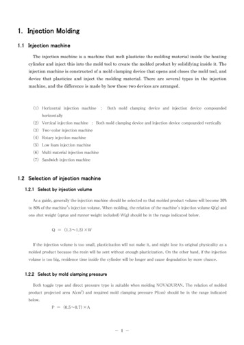
AppendixPneumatic System23
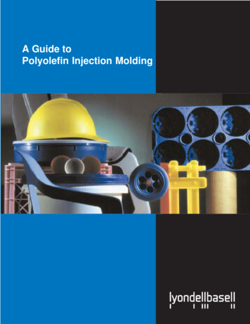
Pilot Valve24
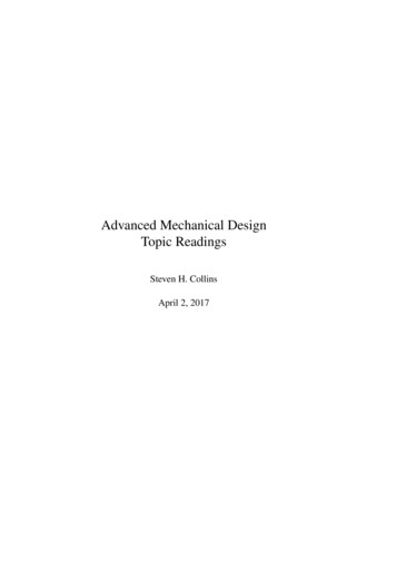
Flow Control Valve25
The Morgan-Press, Model G-100T, is an injection molder designed for practical and economical manufacturing of thermoplastic parts in quantities required for prototyping and low-volume producti