Transcription
Advanced Drafting and CustomizationCATIA V5 TrainingStudent Notes:FoilsCopyright DASSAULT SYSTEMESAdvanced Draftingand CustomizationCopyright DASSAULT SYSTEMESVersion 5 Release 19January 2009EDU CAT EN DRA AF V5R191
Advanced Drafting and CustomizationAbout this courseStudent Notes:Objectives of the courseUpon completion of this course you will be able to set and manageall dimension and annotation standards contained in the standardfiles according to company or projects needs.Targeted audienceDraftsmen, Drafting AdministratorsPrerequisitesCopyright DASSAULT SYSTEMESCATIA V5 Mechanical Design Fundamentals, knowledge of VBscriptingCopyright DASSAULT SYSTEMES16 hours2
Advanced Drafting and CustomizationStudent Notes:Table of Contents (1/2)Hints and Tips on Interactive DraftingAccessing the WorkbenchToolbars DescriptionHints & Tips on Dress Up CommandsHints & Tips on Dimension CommandsHints & Tips on Text CommandsHints and Tips on Generative DraftingGenerating Specific ViewsCreating a Section View/Section Cut with a Profile Defined in .Update ManagementAuto-DimensioningAdvanced Filtering TechniquesBalloons CreationDrawing Generation of Large AssembliesGeneral recommendationsApproximate generation modeCopyright DASSAULT SYSTEMESAdministration tasksAbout Standards and generative View stylesCopyright DASSAULT SYSTEMES56121819324647505152687779808285863
Advanced Drafting and CustomizationStudent Notes:Table of Contents (2/2)Administration of Generative View Styles and StandardsSetting standard parametersSetting standard stylesSetting Generative View StylesAdministration SettingsIncreasing ProductivityGenerating Hole Dimensions TablesCreating Point Coordinates TablesCreating TablesCreating Frames and Title Blocks with a MacroDefining FramesFilling in the Title Block105106107108109110124128Copyright DASSAULT SYSTEMESTo Sum Up88939698101Copyright DASSAULT SYSTEMES4
Advanced Drafting and CustomizationHints & Tips on Interactive DraftingStudent Notes:Copyright DASSAULT SYSTEMESAccessing the WorkbenchToolbars DescriptionHints & Tips on Dress Up CommandsHints & Tips on Dimension CommandsHints & Tips on Text CommandsCopyright DASSAULT SYSTEMES5
Advanced Drafting and CustomizationAccessing the Workbench (1/6)Student Notes:You can access the Drafting Workbench anywhere from :1Copyright DASSAULT SYSTEMES2The Start Menu :The File Menu or the New icon in the Standard toolbar :orCopyright DASSAULT SYSTEMES6
Advanced Drafting and CustomizationStudent Notes:Accessing the Workbench (2/6)You can also create shortcut to access faster the workbench :1Go to Tools Menu and select Customize.Copyright DASSAULT SYSTEMES2Copyright DASSAULT SYSTEMESSelect the Drafting Workbench and add it to the Favorites byclicking the right arrow.You can add anAccelerator toaccess directly theworkbench bypressing a key.7
Advanced Drafting and CustomizationAccessing the Workbench (3/6)3Student Notes:Now you can access the workbench by 3 new ways :When you start CATIAorUsing the Start MenuCopyright DASSAULT SYSTEMESorPressing F12 Key in this caseCopyright DASSAULT SYSTEMES8
Advanced Drafting and CustomizationAccessing the Workbench (4/6)Student Notes:The New Drawing Panel :You can choose differentStandards : ISO, ANSI,ASME,JIS or yourcompany standardCopyright DASSAULT SYSTEMESUse this Option to avoiddisplaying this panel whenaccessing the DraftingWorkbench.Copyright DASSAULT SYSTEMES9
Advanced Drafting and CustomizationStudent Notes:Accessing the Workbench (5/6)You can use the New From function to access the DraftingWorkbench by using an existing drawing with a predefinedformat :1Select an existing drawing to use it as reference.This is a new Drawing andyou can save it withoutkeeping any links with theselected file.Copyright DASSAULT SYSTEMES2Go to File Menu and select New From.Copyright DASSAULT SYSTEMES10
Advanced Drafting and CustomizationStudent Notes:Accessing the Workbench (6/6)When you have accessed the Drafting Workbench you can still make modifications on the Format,the Orientation or the Background using the File/Page Setup command:Change the Standard and update thedrawing with this new Standard.Change the FormatCopyright DASSAULT SYSTEMESYou can choose to apply themodifications on the currentsheet or on all the sheets of thedrawing.Copyright DASSAULT SYSTEMESYou can insert a backgroundview from a selected sheet of another drawing document.11
Advanced Drafting and CustomizationStudent Notes:Toolbars Description (1/6)1The Text Properties Toolbar :You can select a framearound the text or adimension.Be careful, these twospecifications are applied atthe dimension creation.You can use different Fonts asPostscript, True type and V4 type.Copyright DASSAULT SYSTEMESDefault values are defined in thestandard styles. After text creationyou can change the default valuesby selecting a font, a size, analignment, etc.Copyright DASSAULT SYSTEMESText alignmentSelect the anchorpoint position ofthe text.You can add somesymbols in the text. Itallows you to add aprefix symbol to adimension.12
Advanced Drafting and CustomizationStudent Notes:Toolbars Description (2/6)2The Dimension Properties and Numerical Properties Toolbars:Default values are the one definedin the drafting standards. Afterdimension creation you can choosedifferent values.Copyright DASSAULT SYSTEMESYou can modify thedimensional representationof the dimension.Copyright DASSAULT SYSTEMES13
Advanced Drafting and CustomizationStudent Notes:Toolbars Description (3/6)3The Graphic Properties Toolbar :You can copy the format ofone object on selectedobjects.You can select here the line color, the line thickness, the linetype and point type. When you choose a specification, it willbe applied on all the graphics you will create; it becomes aspecification by default.Copyright DASSAULT SYSTEMESYou can also select a graphic then choose a specification toapply on it. In this case, this specification won’t be applied onthe next created graphics.Copyright DASSAULT SYSTEMESYou can select here apattern for the Area Fillfunction.In Standards, youcan add newthickness values14
Advanced Drafting and CustomizationStudent Notes:Toolbars Description (4/6)4The Tools and Visualization Toolbars:These Toolbars are specific because they contain some standard functions and displaysspecific information in accordance with the command you select. Most of time, you have todrag & drop the Toolbar on the screen to display it entirely.ABCDEFHere is the standard Tools toolbar.It’s a kind of shortcut of the menuTools – Options – Drafting.Copyright DASSAULT SYSTEMESCFDimension systemselection mode.You can differentiate 2D elements(Interactive workbench) fromgenerated elements (Generativeworkbench) within the same view.Copyright DASSAULT SYSTEMESGADBEIf you want the constraints to becreated, you must have selected theConstraints creation Option beforeto create geometry.G15
Advanced Drafting and CustomizationToolbars Description (5/6)5Student Notes:The Position and Orientation Toolbar:This Toolbar is not located on a side of the workbench in the default set-up. You have to go inthe View/Toolbars command to select it.You can apply a translation and a rotation to a view,a text or a datum.Copyright DASSAULT SYSTEMESFor a view the reference point is the origin pointand for a text or a datum, the reference point is theanchor point.Copyright DASSAULT SYSTEMES16
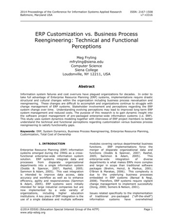
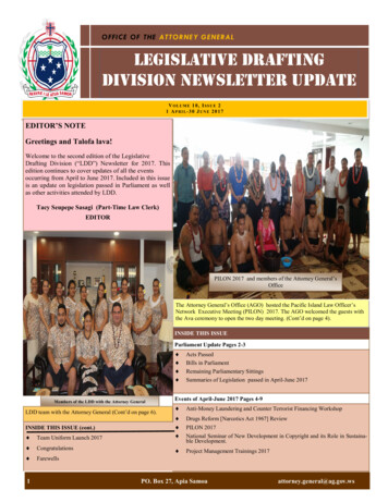
Advanced Drafting and CustomizationStudent Notes:Toolbars Description (6/6)61Create a circle and add a radiusdimension. The Style toolbardisplays the styles available forradius dimensions. In our example,only one style is available, thereforeit will be used by default.In the Graphic Properties toolbar,select another color, red, forexample In the Style toolbar, anasterisk appears in front of theselected style: this asteriskindicates that the style of theelement you are creating has beenoverloaded compared to the stylewhich is defined in the standards.3 Then you can either revert to the standarddefined values (i.e. reset the toolbarproperties to their original values) by reselecting this style from the Styles toolbar,and then clicking to validate and end thedimension creation. The asterisk willdisappear. Or you can apply the modified style byclicking to validate and end the dimensioncreation. For the purpose of this scenario,do this.The dimension is created with the selectedstyle, as defined in the standard andoverloaded by the properties you changed.Copyright DASSAULT SYSTEMES2The Style Toolbar :The styles available in the toolbardepend on what your administratorspecified in the standards.Copyright DASSAULT SYSTEMES17
Advanced Drafting and CustomizationStudent Notes:Hints & Tips on Dress Up CommandsHow to move Axis or Centre Line.If you select a manipulator you will move the Centre Line and the Axis Line along all thedirections with the same length. The modification will be symmetric.Copyright DASSAULT SYSTEMES Ctrl KeyIf you want to move just one line along only onedirection and not symmetrically, you can do it byselecting the concerning manipulator and holding onthe Ctrl Key while you are moving the manipulator.Copyright DASSAULT SYSTEMES18
Advanced Drafting and CustomizationHints & Tips on Dimension Commands (1/13)Student Notes:The way that you can set and manipulate dimensionsdepends on the options that you have checked in theTools Options Drafting panel.1The Dimension following the cursor Option:Copyright DASSAULT SYSTEMESBy selecting this option, whenyou create a dimension, thedimension line is dynamicallypositioned following the cursor.If you want to deactivatetemporarily this mode, you cando it by pressing the Ctrl Key.Copyright DASSAULT SYSTEMES19
Advanced Drafting and CustomizationHints & Tips on Dimension Commands (2/13)2Student Notes:The Snapping Option :By selecting this option, whenyou create a dimension, thedimension is snapped on thegrid or/and the dimension valueto be located at its defaultposition between symbols. If youwant to avoid this, you can do itby holding on the Shift Key.With the Value between symbols option,the dimension value will remain in themiddle of the two extension lines only ifthe mouse cursor stays between thetwo extension lines.Copyright DASSAULT SYSTEMES Shift KeyCopyright DASSAULT SYSTEMESYou can position thedimension value where youwant.20
Advanced Drafting and CustomizationHints & Tips on Dimension Commands (3/13)3Student Notes:The Move only selected sub-part Option :The Move only selected sub-partoption allows you to move only adimension sub-part like a text, aline, the dimension value, etc.Copyright DASSAULT SYSTEMESFor example, you can move the dimensionvalue even if you have selected the Snap bydefault option.Copyright DASSAULT SYSTEMES21
Advanced Drafting and CustomizationHints & Tips on Dimension Commands (4/13)4Student Notes:The Dimension Circle Option :Copyright DASSAULT SYSTEMESBy selecting this option, thedimension you will createbetween a circle and anotherelement will be either on thecircle center or on the circleedge. If you want to change thisoption during the creation, youcan do it by using the yellowmanipulator which is displayed.Select the manipulator with MB1 anddrag it to choose one of the 3 proposedlocations. If you have chosen theDimension following the cursor optionuse CTRL KEY.Copyright DASSAULT SYSTEMES22
Advanced Drafting and CustomizationHints & Tips on Dimension Commands (5/13)5Student Notes:The Diameter Dimension Options :During the dimension creation step, you can switchbetween one-symbol or two-symbols dimension.Copyright DASSAULT SYSTEMESOnce the dimension has been created,you must use the Properties menu(Dimension Line tab) to specify whetheryou want to use one or two-symbols.After the Diameter Dimension creation,you can swap to Radius Dimension byusing the contextual menu.Copyright DASSAULT SYSTEMES23
Advanced Drafting and CustomizationHints & Tips on Dimension Commands (6/13)6Student Notes:The Angle dimensions Creation :You can also edit the angle sector of anexisting angle dimension, by right-clickingthe angle dimension and selecting theDimension name object - Angle Sectorcommand from the contextual menu.Copyright DASSAULT SYSTEMESDuring angle dimension creationyou can move the dimension toa new sector by using the AngleSector contextual menuCopyright DASSAULT SYSTEMES24
Advanced Drafting and CustomizationHints & Tips on Dimension Commands (7/13)7Student Notes:The Create driving dimension Option :Select this Option if you want tocreate driving dimensions bydefault.Copyright DASSAULT SYSTEMESDuring the dimensions creation,you can set directly the value inthe Tools Palette toolbar.Copyright DASSAULT SYSTEMES25
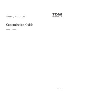
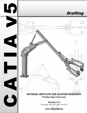
Advanced Drafting and CustomizationStudent Notes:Hints & Tips on Dimension Commands (8/13)8The Line-Up Options:The Line-Up function allows you to positionlength, distance, radius, diameter an angledimensions according to a given reference.To define the distance and the angle inrelation with the reference element.To define the distance and the anglebetween each dimension you line up.Define de Line-upparametersCopyright DASSAULT SYSTEMESSelect thereference elementCopyright DASSAULT SYSTEMES5mm10mm26
Advanced Drafting and CustomizationHints & Tips on Dimension Commands (9/13)9Student Notes:Creating Chamfer Dimensions :During the creation of the chamferdimension, you can define the format of thedimension and the representation mode inthe Tools Palette toolbar.Copyright DASSAULT SYSTEMESYou can also modify those propertiesafterwards by accessing the Chamfer tab inthe dimension properties.Copyright DASSAULT SYSTEMES27
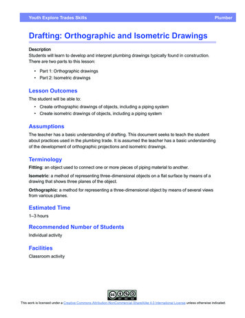
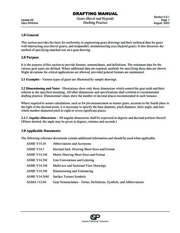
Advanced Drafting and CustomizationHints & Tips on Dimension Commands (10/13)10Student Notes:Creating Coordinate Dimensions :The Tools palette appears with two options:2D Coordinates lets you create 2D (x, y)coordinate dimensions for interactivegeometry, 3D Coordinates lets you create3D (x, y
Student Notes: Advanced Drafting and Customization Copyright DASSAULT SYSTEMES 17 C o p y r i g h t D A S S A U L T S Y S T E M E S Toolbars Description (6/6) 6 The .