Transcription
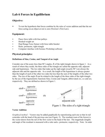
Lab 6 Forces in EquilibriumObjective: To test the hypothesis that forces combine by the rules of vector addition and that the netforce acting on an object at rest is zero (Newton’s First Law).Equipment: Pasco force table with four pulleysHooked weight setDual Range Force Sensor with force table bracketRuler, protractor, right triangleComputer interface with Science Workshop softwarePhysical principles:Definitions of Sine, Cosine, and Tangent of an AngleConsider one of the acute (less than 90E) angles, 2, of the right triangle shown in figure 1. As aresult of where they reside, the three sides of the triangle are called the opposite side, adjacentside and hypotenuse. The two sides that make up the right angle (exactly 90E) are always theadjacent side and the opposite side. As a result, the length of the hypotenuse is always greaterthan the length of each of the other two sides but less than the sum of the lengths of the other twosides. The size of the angle 2 can be related to the length of the three sides of the right triangleby the use of the trigonometric functions Sine, Cosine and Tangent, abbreviated sin, cos and tan,respectively. They are defined as shown in Figure 1.oppositehypotenuseadjacentcosθ hypotenuseoppositetan θ adjacentsin θ (1)Vector AdditionGraphical method - Vectors may be added graphically by repositioning each one so that its tailcoincides with the head of the previous one (see Figure. 2). The resultant (sum of the forces) isthe vector drawn from the tail of the first vector to the head of the last. The magnitude (length)and angle of the resultant is measured with a ruler and a protractor, respectively. Note: In order
to measure the angle, a set of axes must first be defined.Component method - Vectors may be added by selectingtwo perpendicular directions called the X and Y axes, andprojecting each vector on to these axes. This process iscalled the resolution of a vector into components in thesedirections. If the angle a that the vector makes from thepositive X axis, is used (see Figure 3), these componentsare given byFx F cosθFy F sin θ(2)Figure 2 Vector addition by thepolygon method.The X component of the resultant is the sum of the Xcomponents of the vectors being added, and similarly for theY component. The angle that the resultant makes with the Xaxis is given by F θ tan 1 y Fx (3)and the magnitude is given byF Fx2 Fy2(4)Figure 3 Finding the twoperpendicular components of avector.Equilibrium ConditionsNewton's first law predicts that a body will not accelerate when the net force acting on it is zero.So, for an object to be at rest, the resultant force acting on it is zero. Thus, if three forces act onan object at rest, the following relationship has to be satisfied.r rrF1 F2 F3 0(5)An equivalent statement isrr rF3 ( F1 F2 )(6)so that F3 is equal in magnitude and opposite in direction to the vector sum of the other twoforces.
Prediction:Suppose you have one force, of magnitude 3.0N, directed in the positive x direction (21 0E),and a second force, of magnitude 4.0 N,direction in the positive y direction (22 90E).In your journal, draw a graph that includes thesetwo forces (to scale), the vector sum of thesetwo forces, and the needed force that would beequal in magnitude and opposite in direction tothe resultant of these two forces. What is themagnitude and direction of F ?Figure 4. Pasco Force Table with DualRange Force Sensor balancing two forces.Procedure:Setup Science Workshop:1.Connect the din plug from the force sensor into analog channel A of the ScienceWorkshop Interface.2.Open Science Workshop.3.Click on Sampling Options to change the sampling rate to 500 Hz. Set a stop time of 2 s.4.Click and drag the analog plug (right hand side) icon to analog channel A, choose ForceSensor.5.Double click on the Force Sensor icon below analog channel A, to calibrate.6.Enter 0 in the Low Value box on the left. With no tension in the force sensor string clickon the Low Value Read to enter the voltage for zero force.7.Support 500 g of hooked weights from the end of one of these strings across a pulley andconnect a second one to the force sensor. Position the force sensor opposite the pulley.The tension force equals the weight of the mass, which is (0.500 kg)(9.8 m/s2) 4.90 N.Position this pulley opposite the force sensor. Be sure that the string is perpendicular tothe end face of the force sensor. Enter 4.9 in the High Value box on the left. Click on theHigh Value Read to enter the voltage for the 4.9 N force. Click on OK to accept thecalibration.8.Click and drag the graph icon onto the force sensor icon. Click on the statistics icon E onthe lower left, then click on the E in the statistics window and select Count. Similarlyselect Mean and Standard Deviation.Data collection:Set up the following situations so that in each case the magnitudes of the forces are unequal. Ineach case, adjust the position of the force sensor in both the angular and radial direction so thatthe knot in the strings is exactly over the cross-hairs in the center of the force table. The pulleysshould be adjusted so that the strings are exactly horizontal and as close to the force table aspossible without actually touching the table.
1. Support hooked masses of 200 g (F1 0.200 kg * 9.8 m/s2 1.96 N) and 300 g (F2 0.300 kg * 9.8 m/s2 2.94 N) fromstrings over the pulleys so that the angle between forces F1 andF2 is 90E as shown in Figure 5. The force FFS is the valuedisplayed by the force sensor. Enter in Table 1 the two massesand weights F1, and F2. Click on REC and click and drag toselect the force data. Record the value of the force FFS and itsstandard deviation. From the force table record the direction2FS that the force sensor string is pulling. Compute themagnitude and direction of the sum of the forces F1 and F2using equations (3) and (4) and compare your result withFigure 4 Force table setup with2FS - 180E and FFS.two forces balanced by the forceSelect your x axis to be along the line of force F1 at the angle sensor.of 0E. Make a sketch in your journal showing these forces asarrows and write the values of each force alongside its arrow. Draw to scale two vectors for F1and F2 and add the vectors graphically. Use at least 1/2 of a page for the graphical solution inorder to improve the accuracy of your measurement. Then compare the results from the forcesensor with the graphical measurements.2. Support three different masses in an arrangementapproximately as shown in Figure 6. Record the masses inTable 2. Calculate and record in table 2 the weight forces andforce components. Add the components of F1, F2, and F3.Compute the magnitude and direction of the sum of theseforces using equations (3) and (4) and compare your resultwith 2FS - 180E and FFS.Make a sketch in your journal showing these forces as arrowsand write the values of each force alongside its arrow. Draw arough sketch of the sum of these vectors. Label each vectorFigure 6 Force table setup withand the sum.three forces.Conclusions:In your conclusions, discuss whether your measurements satisfy the requirements of Newton’sFirst Law. What can you say about the proposition that forces combine according to the rules ofvector addition?For extra credit repeat the measurements and calculations you did in step 2 using four differentweight forces. Compare the measured force sensor result with the calculated component methodsolution for the four weight forces. Do these results satisfy the requirements of Newton’s FirstLaw?
Table 1 Adding two forces that are at 90EMass m (kg)Weight m* g (N)F1 (along x, 21 0E)F2 (along y, 22 90E)2FS FFS Fcalc Fx2 Fy2 % error of F 100 2FS - 180E Fy θcalc tan 1 Fx ,FFS Fcalc Fcalcangle error 2FS - 180E - 2calc Table 2 Adding three forces by the component method.Mass (kg)m*g (N)Angle 2Fx (N)F1 (along x, 21 is zero)Fy (N)0F2 (22 is in the first quadrant.)F3 (21 is in the second quadrant)Components of the vector sum of F1 and F22FS FFS Fcalc Fx2 Fy2 % error of F 100 FFS Fcalc Fcalc2FS - 180E , Fy θcalc tan 1 Fx angle error 2FS - 180E - 2calc
Lab 6 Forces in Equilibrium Objective: To test the hypothesis that forces combine by the rules of vector addition and that the net force acting on an object at rest is zero (Newton’s First Law). Equipment: Pasco force table with four pulleys Hooked weight set Dual Range Force Sensor with force table bracket Ruler, protractor, right triangle Computer interface with Science .