Transcription
Uplift Pressures below Spillway Chute Slabs atUnvented Open Offset JointsDownloaded from ascelibrary.org by Tony Wahl on 09/13/19. Copyright ASCE. For personal use only; all rights reserved.Tony L. Wahl, P.E., M.ASCE 1; K. Warren Frizell 2; and Henry T. Falvey, Dr.Eng., D.WRE, M.ASCE 3Abstract: The catastrophic failure of the spillway chute at Oroville Dam in February 2017 raised concerns throughout the water resourcesindustry regarding design, construction, and maintenance practices for concrete spillway chutes, especially joints and cracks that could allowpenetration of high-pressure water into a chute foundation. The independent forensic team investigation found that hydraulic jacking was themost likely cause of the initial chute slab failure, highlighting a need for better analysis of the hydraulic jacking potential of existing spillwaysand more resilient designs for spillways that operate under high-velocity flow conditions. This paper reviews the Oroville Dam event andfindings and previous laboratory testing performed to evaluate uplift pressures and flow transmitted through spillway joints. A reanalysis ofprevious studies was used to develop relations between chute velocity, joint geometry, and uplift pressure transmitted into a joint. Upliftpressure head in these relations is expressed in a dimensionless manner, either as a percentage of the velocity head in the boundary layer atmidheight of the offset into the flow, or as a percentage of the channel-average velocity head. The first approach is potentially more useful forprototype applications, but the second method provides the best fit to the available experimental data. Additional research is still needed toquantify rates of flow through open joints, confirm relations between uplift pressure and boundary layer velocities, and evaluate the effects ofaerated flow. DOI: 10.1061/(ASCE)HY.1943-7900.0001637. 2019 American Society of Civil Engineers.IntroductionThe February 2017 failure of the spillway chute at Oroville Dam,owned and operated by the California Department of WaterResources (DWR), raises significant concerns about aging spillway structures. As dams and spillways age, concrete surfaces andmasses slowly deteriorate, slabs may shift because of foundationsettlement or frost heave, reinforcement bars and anchors maycorrode and lose strength, and auxiliary components such as underslab drain systems can be compromised by sediment deposition,scour, and intrusion of tree roots. Once concrete surfaces sufferinitial deterioration, other problems become more likely, includingcavitation damage, increased uplift forces at joints, and accelerationof deterioration rates due to freeze-thaw action.One of the most likely locations for problems to occur in a concrete spillway chute is at or near the joints. Common types of jointsinclude construction joints, control joints, expansion joints, andcontraction joints. Joints typically deteriorate faster than slabs,and they offer opportunities for surface offsets and entry of pressurized flow into foundation areas, key elements for cavitation andhydraulic jacking failure modes. Even if uplift pressures are notlarge enough to cause immediate slab movement, the flows thatenter the foundation through open joints can cause erosion and thedevelopment of voids beneath slabs that may ultimately lead to slabmovement, offsetting of joints, and uplift.1Technical Specialist, Bureau of Reclamation, Hydraulic Investigationsand Laboratory Services, Denver, CO 80225-0007 (corresponding author).ORCID: https://orcid.org/0000-0002-2081-2263. Email: twahl@usbr.gov2Retired; formerly, Hydraulic Engineer, Bureau of Reclamation, Hydraulic Investigations and Laboratory Services, Denver, CO 80225-0007.3Consultant, Henry T. Falvey & Associates, 11624 Blackfoot Rd.,Conifer, CO 80433.Note. This manuscript was submitted on October 5, 2018; approved onMarch 22, 2019; published online on September 13, 2019. Discussionperiod open until February 13, 2020; separate discussions must be submitted for individual papers. This paper is part of the Journal of Hydraulic Engineering, ASCE, ISSN 0733-9429. ASCEDespite their problems, joints are a practical necessity becausespillways are large structures that typically must be constructed in aspecific sequence and in multiple phases over several months oryears. Joints placed at regular intervals enable staged construction,permit thermal contraction and expansion, and help to controlcracks in the finished product. The geometry and constructiondetails of joints vary, which affects their vulnerability to upliftand seepage flow. Although modern design standards for spillwayjoints (e.g., Bureau of Reclamation 2014) include details meant toprevent the development of offsets and gaps (e.g., keys, structuralreinforcement) and limit flow through joints (waterstops), olderspillways like Oroville lack some or all of these features or haveother deficiencies (e.g., poorly prepared foundations, inadequate ordeteriorated drainage systems) that make them vulnerable to upliftfailures.Hydraulic jacking occurs when the forces acting to lift a spillway slab exceed the forces resisting upward movement. Resistingforces include the weight of the slab itself, the capacity of foundation anchors, and the pressure applied to the top of the slab by waterflowing in the chute. Uplift can be created through a combination ofincreased pressure below the slab and reduced pressure above theslab (i.e., lift). High pressures can be generated below a slab whenhigh-velocity flow stagnates against an offset into the flow at a jointthat is open to the foundation. Offsets can occur due to settlement ofan upstream slab or lifting or tilting of the edge of a downstreamslab, or with no slab movement when the concrete surface is spalledupstream from a joint. Slab movements that lead to offsets mayoccur because of drying or wetting of soil foundations, frost heave,or internal erosion of foundation soils when flow through openjoints is not captured or retained within a drainage system. Wheninternal erosion leads to the development of large voids beneath aslab, this may enable high pressures generated at a joint to morereadily act over a large area beneath the slab.Lift on the top surface of a slab can occur because of gradualcurvature of the spillway surface away from the flow, or abruptseparations of flow from the spillway surface. Steps up or downcaused by misalignment of joints are capable of generating localized04019039-1J. Hydraul. Eng., 2019, 145(11): 04019039J. Hydraul. Eng.
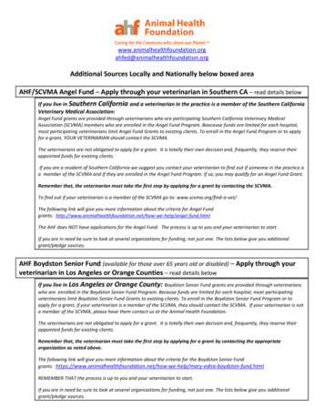
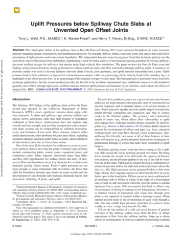
Downloaded from ascelibrary.org by Tony Wahl on 09/13/19. Copyright ASCE. For personal use only; all rights reserved.low-pressure zones. Dong et al. (2010) studied cavitation at offsetsinto the flow and measured negative pressures approaching the vapor pressure of water in the separation zone downstream from 2- and5-mm-high offsets, but pressure recovery was also observed to begin75–100 mm downstream. Vapor pressure establishes the minimumpossible pressure on the upper surface of a spillway slab, limitingthe contribution of flow separation to the uplift head to about 10 m(33 ft), but stagnation pressure heads associated with high-velocityflow can be much larger. For example, the stagnation pressure associated with a velocity of 30 m s (98 ft s) is about 46 m (151 ft).For this reason, most analyses of uplift forces have focused on thepressure increase beneath the slab. In previous experimental work tobe discussed later in this paper, the reported uplift was the net difference between the increased pressure below the slab and the pressureabove the slab associated with a relatively shallow flow depth.Additional factors that may be important in spillway slab upliftare air entrained in the flow above the slab and its effect on pressures generated within the joints, and the role of fluctuating pressures in combination with steady uplift. These two factors mayalso be linked to some degree, as Bollaert and Schleiss (2003a, b)showed that air is an important factor in creating a resonance effectthat magnifies pressure fluctuations within closed-end fissures infractured rock masses.Hepler and Johnson (1988) and Trojanowski (2004) documentedhydraulic jacking failures in Bureau of Reclamation spillways atDickinson Dam (North Dakota) in 1954 and at Big Sandy Dam(Wyoming) in 1983. At Dickinson Dam, there was a lack of defensive design features such as foundation grouting, anchor bars, andwaterstops, and the underdrain system was compromised by subfreezing temperatures. In addition, there were several possiblemechanisms that could have led to joints with offsets and openingsthat permitted pressurized flow to enter the foundation. Unfilteredgravel zones around the underdrain system were also implicated asa factor in internal erosion that led to the development of voidsbeneath the slabs. At Big Sandy Dam, freezing temperatures overmany years caused deterioration of the spillway concrete, damage tothe underdrain system, and slab movement that produced open andoffset joints. Uplift pressures at the time of failure were large enoughto pull the foundation rock anchors out of the soft sandstone foundation [1.2-m (4-ft)–long, 25-mm (1-in.)–diameter bars on 1.5-m(5-ft) centers, with a design capacity of 44 kN (10 kips) each].It was speculated that the anchors may have been only 50% effective because of deterioration of the grout-foundation contact andcould have been failed by an uplift pressure head greater than49% of the mean velocity head, which was a feasible failure scenario (Trojanowski 2004). Considering these failures and experiences from other spillways exhibiting various types of distress,Trojanowski (2008) discussed the evaluation of potential failuremodes of spillways, including factors related to hydraulic jacking.delivery system in the United States. On February 7, 2017, the service spillway chute lining failed, leading to an emergency that lastedfor several weeks while the spillway was required to continueoperating.At the time of the failure, Oroville Dam was equipped with twospillways. The gated spillway, described as the service spillway orflood control outlet (FCO), was controlled by eight large top-sealradial gates and discharged into a concrete chute that was 54.5 m(178.67 ft) wide and 914 m (3,000 ft) long. The emergency spillway, which had never operated, was a 518-m (1,700-ft)–long uncontrolled overflow weir discharging into an unimproved steepnatural drainage leading back to the Feather River. The servicespillway chute was originally designed for a maximum flow rate of7,080 m3 s (250,000 ft3 s). The historical maximum instantaneous discharge was 4,530 m3 s (160,000 ft3 s) in 1997, about 64%of the design discharge (IFT 2018). The spillway had operated infrequently in its 49-year history, with about 4 days of operationabove 2,830 m3 s (100,000 ft3 s), 40 days above 2,120 m3 s(60,000 ft3 s), and 300 days above 1,060 m3 s (30,000 ft3 s).Soon after construction was completed, cracking of the spillwayslab occurred over embedded drain pipes, which were arranged ina herringbone pattern down the length of the spillway. As result,there was a long history of periodic repairs made to maintain theservice spillway chute slab.Due to heavy snow and rain in northern California in thewinter of 2016–2017, the service spillway operated for aboutfive days in mid-January 2017 at flow rates up to about 283 m3 s(10,000 ft3 s)—the first significant flows since 2011. The spillwaywas shut down around January 20 and then restarted aroundFebruary 1. Discharges were gradually increased during earlyFebruary. At about 10:10 a.m. on the morning of February 7, whilethe discharge was being increased from 1,200 to 1,490 m3 s(42,500 to 52,500 ft3 s), DWR personnel working near the left sideof the service spillway chute heard a loud sound they compared toan explosion. They subsequently observed spray and significantlydisturbed flow conditions in the spillway chute near Station 1,020 m(33 þ 50 ft), about 640 m (2,100 ft) downstream from the spillwayradial gates. The spillway continued to operate for about one hour,and then, from about 11:25 a.m. to 12:25 p.m. the spillway gateswere closed, revealing the damage shown in Fig. 1.Because of forecasted large inflows, a continued need forspillway operations was anticipated. Following initial damage assessments and release of some closely monitored test flows, theOroville Dam Spillway FailureThe description of the Oroville Dam spillway chute failure givenin this section is summarized from the report of the Oroville DamIndependent Forensic Team (IFT 2018).Oroville Dam is an embankment dam located on the FeatherRiver in northern California—the tallest dam in the United Statesat 235 m (770 ft). The dam is owned and operated by DWR, whichwas responsible for design and construction, completed in 1968. Itis one component of the Oroville-Thermalito Complex, which includes several hydroelectric powerplants, canals, and diversion andfish barrier dams. The complex is a major feature of the CaliforniaState Water Project, the largest state-owned water storage and ASCEFig. 1. Spillway damage observed after gates were initially closed atmidday, February 7, 2017. (Reprinted from IFT 2018, with permission.)04019039-2J. Hydraul. Eng., 2019, 145(11): 04019039J. Hydraul. Eng.
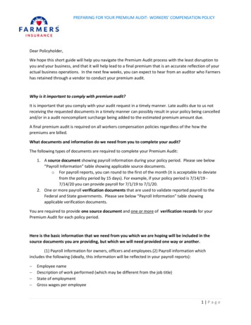
Downloaded from ascelibrary.org by Tony Wahl on 09/13/19. Copyright ASCE. For personal use only; all rights reserved.Fig. 2. Ultimate damage at the Oroville Dam service spillway inMay 2017. (Reprinted from IFT 2018, with permission.)spillway was placed back into service from February 8 to February10 at discharges up to 1,840 m3 s (65,000 ft3 s), with erosionand damage to the chute structure continuing. Unfortunately, thesereleases were not enough to keep up with inflow to the reservoir.Early on February 11, the reservoir level exceeded Elevation274.62 m (901 ft) and the emergency spillway began to flow forthe fir
failures. Hydraulic jacking occurs when the forces acting to lift a spill-way slab exceed the forces resisting upward movement. Resisting forces include the weight of the slab itself, the capacity of theslabbywater ationof