Transcription
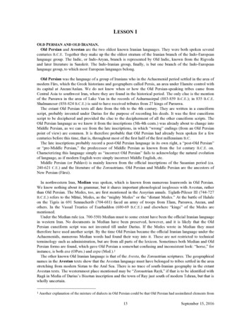
Q6 (Advanced 6 year old child)User Manual
For information on Humanetics products, please visit our web site atwww.humaneticsatd.com or contact:Humanetics Innovative Solutions47460 Galleon DrivePlymouth, MI 48170, USATelephone: 734-451-7878Fax: 734-451-9549No part of this publication may be reproduced, stored in a retrieval system or transmitted inany form or by any means, electronic, photocopying, recording, mechanical or otherwise,without the express written consent of Humanetics Innovative Solutions.Copyright 2016 Humanetics Innovative Solutions, All rights reserved.The information in this manual is furnished for informational use only, and is subject tochange without notice. Humanetics Innovative Solutions assumes no responsibility or liabilityfor any errors or inaccuracies that may appear in this manual.Notice: This product may contain leadA list of components that may contain lead is being maintained on the Humanetics website.The list, organized by dummy type, shows subcomponents that may currently or in the pasthave contained lead or a lead based alloy. Please refer to the Humanetics website underATD Lead Disclosure for information regarding lead in this product.http://www.humaneticsatd.com/Lead DisclosurePage 2 of 96033-9900 User Manual Q6 (Advanced 6 year old) Rev. M 2016 Humanetics Innovative Solutions Inc.
Content1.Introduction . 72.General Description and Features . 82.1Design History. 82.2Applications . 82.3Features . 92.4Instrumentation Options. 122.5Main Dimensions . 122.6Mass Distribution . 132.7Standard Dummy. 133.Instrumentation . 143.1General . 143.2Transducers . 143.3Accelerometer Mounts . 173.4Angular Velocity Sensor Mounting . 193.5Abdomen Pressure Twin Sensor (ATPS) . 213.6Cable Routing and Protection . 234.Assembly - Disassembly . 244.1General Overview . 244.2Head . 254.3Neck. 284.4Torso . 324.5Lumbar Spine and Abdomen . 404.6Pelvis. 444.7Legs . 464.8Arms . 484.9Abdomen . 51Page 3 of 96033-9900 User Manual Q6 (Advanced 6 year old) Rev. M 2016 Humanetics Innovative Solutions Inc.
4.10 Neck Shield . 524.11 Suit . 534.12 Hip Insert . 535.Pre-Test Checks . 545.1Inspection . 545.2Click Stops and Arm Adjustment . 555.3Time Interval between Tests . 566.Dummy Parts List and Recommended Spare Parts . 576.1Dummy Parts . 576.2Recommended Spare Parts . 607.Certification Equipment . 617.1Requirements . 617.2Equipment . 627.3Equipment Parts List . 678.Certification Tests . 688.1Head Certification. 688.2Certification of the Neck . 728.3Certification of the Lumbar Spine . 788.4Certification of the Abdomen. 848.5Certification of the Thorax . 859.10.Markers Location Coordinates and Relevant Dimensions . 92Manual Update Log . 94Page 4 of 96033-9900 User Manual Q6 (Advanced 6 year old) Rev. M 2016 Humanetics Innovative Solutions Inc.
List of FiguresFigure 1.Q0 – Q6 dummies: from left to right Q1.5, Q3, Q0, Q6 and Q1 . 7Figure 2.Accelerometer mounts for Q6 . 18Figure 3.Thorax uni-axial acceleration mounts I.AO (left) and I.AN (right) . 18Figure 4.Pelvis uni-axial acceleration mounts I.AO (left) and I.AN (right) . 18Figure 5.Head uni-axial acceleration mounts I.AD (left) and I.AM (right) . 18Figure 6.ATA ARS-01 (left) and ARS-06 (flanged version) (right) . 19Figure 7.DTS ARS’s on the special mount (DTS drawing TRIAX-M2D-1168) . 20Figure 8.Q6 Head instrumentation. 20Figure 9.40 mm APTS sensor . 21Figure 10.CAD Picture of Q6 Abdomen showing ATPS sleeves assembled without sensorsand with foam plugs for certification . 22Figure 11.Q6 Head assembly (standard and optional instrumentation brackets shown). 26Figure 12.Q6 Neck assembly . 29Figure 13.Q6 Thorax assembly . 33Figure 14.IR-TRACC attachment hardware spine frontal (top left and right) and rib cageside (bottom) . 37Figure 15.IR-TRACC should swing freely . 38Figure 16.Q6 side impact IR-TRACC arrangement . 39Figure 17.Lumbar spine assembly and abdomen . 43Figure 18.Pelvis and hip joint assembly . 45Figure 19.Leg Assemblies . 47Figure 20.Arm Assemblies . 49Figure 21.Neck Shield Installed: Left, Rear view; Right, Front view . 52Figure 22.Hip insert fitted on Q6: sitting position (left), straight legs (right) . 53Figure 23.Neck and lumbar spine head form test set-up for frontal test . 62Figure 24.Neck and lumbar spine head form test set-up for lateral test . 63Figure 25.Q6 full-body impactor (accelerometer not shown) . 65Figure 26.Full body pendulum impactor suspension wire diagram . 66Figure 27.Frontal Head drop certification set-up . 70Figure 28.Lateral Impact Head certification set-up – rear view of head . 71Figure 29.Q6 neck certification test set-up for frontal test . 74Figure 30.Q6 neck certification test set-up for lateral test . 76Figure 31.Q6 lumbar spine certification test set-up for frontal test . 80Figure 32.Q6 lumbar spine certification test set-up for lateral test . 82Figure 33.Abdomen certification test set-up . 84Figure 34.Neck Shield Installed and Removed . 86Figure 35.Marker Positions on the Dummy. 92Page 5 of 96033-9900 User Manual Q6 (Advanced 6 year old) Rev. M 2016 Humanetics Innovative Solutions Inc.
List of TablesTable 1.Main dimensions . 12Table 2.Mass distribution . 13Table 3.Uni-axial accelerometers and mounts for thorax and pelvis . 17Table 4.Tri-axial accelerometers and mounts for head . 19Table 5.Assembly and component part numbers for abdomens that can engage APTSsensors . 22Table 6.Head assembly parts . 25Table 7.Neck assembly parts. 28Table 8.Torso assembly parts . 32Table 9.IR-RTRACC attachment: part list frontal impact configuration . 36Table 10.IR-RTRACC attachment: part list frontal impact configuration. 39Table 11.Spine and abdomen assembly parts . 41Table 12.Pelvis assembly parts . 44Table 13.Legs assembly parts . 46Table 14.Arm assembly parts. 49Table 15.Dummy parts list . 57Table 16.Recommended spare parts . 60Table 17.Q6 full body pendulum specifications . 65Table 18.Q-Dummy certification equipment parts list . 67Table 19.Markers Head, Origin: Occipital Condoyle . 93Table 20.Markers Torso, Origin: Erected seating, Seat back (cable guide), bottom of pelvisflesh- and Mid-sagittal-plane . 93Table 21.Markers Arms, Origin: Elbow joint centre, Upper arm bone vertical, Lower armbone horizontal . 93Table 22.Markers Legs, Origin: Knee joint centre, Upper leg bone horizontal, Lower legbone vertical . 93Page 6 of 96033-9900 User Manual Q6 (Advanced 6 year old) Rev. M 2016 Humanetics Innovative Solutions Inc.
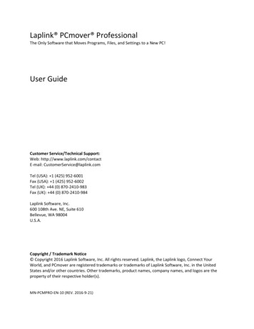
1. IntroductionIn the late 1970s and early 1980s, TNO and others developed the P-dummies, aseries of child dummies that covers almost the complete child population up to12 years. The P-series dummies are still test tools for the European regulationECE-R44 and are also adopted by many other standards.In 1993, the International Child Dummy Working Group started the developmentof a new series of child dummies as a successor to the P-series. This new serieswas called the Q-series. Part of the development and evaluation of the Q-dummiestook place within European Research programs like CREST1, CHILD2, CASPER3 andEPOCh4 all aiming at improving child safety in cars. As of December 2011, theseries is available in five age groups, representing a Newborn, 1 year, 1½ year, 3year, 6 year and 10 year old child.Nowadays members of this Q family are applied in UNECE Regulation R129, whichbecame effective per January 2013. Also, various consumer rating programsworld-wide apply Q dummies.Humanetics reserves the right to make improvements or implement changes tothe dummy, the certification or the user manual if this is deemed necessary. Wewill of course inform our customers of any changes or modifications should theyoccur.Figure 1.Q0 – Q6 dummies: from left to right Q1.5, Q3, Q0, Q6 and Q11CREST. “Child Restraint System for Cars”, EC-contract number C-RTD SMT4-CT95-2019.2CHILD. “Child Injury Led Design”, EC-contract number G3RD-CT-2002-00793CASPER. “Child Advanced Safety Project for European Roads”, EC Grant Agreement 218564.4EPOCh. “Enabling Protection for Older Children”, EC Grant Agreement 218744Page 7 of 96033-9900 User Manual Q6 (Advanced 6 year old) Rev. M 2016 Humanetics Innovative Solutions Inc.
2. General Description and Features2.1Design HistoryThe development of the Q-series, directed by the International Child DummyWorking Group, resulted in a Q3 dummy in 1998, followed by the addition of theQ6 dummy in 1999, and the Q1 in 2000.Based on customer feedback and test results, Humanetics have receivedcomments on the dummies’ performance and durability. This has resulted in anupdate program that was started in 2004. This update was aimed at a number ofissues with the Q dummies in the shoulder, and head/neck area. During thisperiod, the Q0 and Q1.5 were added to the family, based on Q-seriesanthropometry and biofidelity data.The European Enhanced Vehicle-safety Committee performed an extensiveevaluation program of the Q-series in 2004. A full report on a possiblerecommendation for use of the dummies in ECE R44 tests is expected in 2005.Results of the first evaluations have been published at the 19th Enhanced Safetyof Vehicles conference in 20055. In 2006, the New Programme for the Assessmentof Child-restraint Systems (NPACS) adopted the Q dummies for their testprotocols.2.2ApplicationsThe Q6 dummy is suitable for frontal as well as side impact CRS evaluations, tobe used for both homologation, consumer rating and research purposes.Applications include: Child Restraint Systems (CRS) type approval testing. This includes the UNECERegulation R129 in which the Q6 dummies will be applied from July 2017 on toassess non-integral Child Restraint Systems (CRS). The Regulation R129 isbeing introduced in phases including front and side assessment of CRS.5 Assessing New Child Dummies and Criteria for Child Occupant Protection in Frontal Impact, Kate de Jageret. Al, Enhanced Safety of Vehicles conference 2005. Paper no. 05-0157.Page 8 of 96033-9900 User Manual Q6 (Advanced 6 year old) Rev. M 2016 Humanetics Innovative Solutions Inc.
Consumer rating tests. The dummy has been designed to withstand impact withclosing velocities up to an average Euro NCAP level. Since January, the Q6 isbeing used in the Euro NCAP protocols together with the Q10 dummy. OtherNCAP organizations like A-NCAP will follow at a later point in time. The European Test Consortium (ETC) for Child Restrain Seats uses the Q seriesfor their frontal and side impact consumer test procedures for CRS performancerating6. Out-of-position tests (OOP), including airbag interaction.2.3Features The Q-dummies have improved biofidelity over the P-series. Biomechanicalinformation from children and scaled adult biomechanical response curves hasbeen used to define the dummy response. The anthropometry of the dummy isbased on CANDAT7 data. The dummies can be equipped with accelerometers, angular velocity sensors,load cells and displacement sensors. This allows evaluation of the injury riskunder various circumstances. Special attention has been paid to the handling characteristics of the dummy,ensuring the dummy can be assembled and disassembled quickly, andinstalling the dummy in the test configuration is simple and repeatable. The influence of transducers upon the kinematics of the dummy is minimized,and protection of transducers and cables is integrated in the dummy design.6 New Program for the Assessment of Child Restraint Systems (NPACS), V. Sandner et., Enhanced Safety ofVehicles conference 2009.7 Anthropometric of Children for Dummy Design, D. Twisk et. Al., ECOSA Product Safety Conference.Amsterdam. 1993.Page 9 of 96033-9900 User Manual Q6 (Advanced 6 year old) Rev. M 2016 Humanetics Innovative Solutions Inc.
HeadThe head is largely made from synthetics. The head cavity is large enough to allowuse of several instruments, including linear accelerometers and angular velocitysensors.NeckThe neck is flexible and allows shear and bending in all directions. The segmenteddesign allows a realistic rotational behavior. The neck is equipped with low stretchneck-cord in order to prevent excessive elongation. The neck-cord is alsodesigned to act as a safety cord in case of rubber failure. A six channel load cellcan be mounted at the neck-head and neck-torso interface.ThoraxThe thorax of the child is represented by a single rib cage. The deformation canbe measured with an IR-TRACC (Infra-Red Telescoping Rod for Assessment ofChest Compression) sensor. The shoulders are connected with a flexible joint tothe thorax, allowing deformation forward. Accelerometers can be mounted onthe spine to measure linear accelerations.AbdomenThe abdomen is foam covered with skin. Biomechanical data from children hasbeen used to determine the required stiffness.Lumbar SpineThe lumbar spine is a flexible rubber column, with a steel cable, which allowsshear and bending in all directions. A six channel load cell can be mountedbetween the lumbar spine and the pelvis.Page 10 of 96033-9900 User Manual Q6 (Advanced 6 year old) Rev. M 2016 Humanetics Innovative Solutions Inc.
PelvisThe Q-dummy pelvis has removable hip joints. An accelerometer array can bemounted in the pelvis. Special hip joints are available that allow the dummy to beposition in a standing posture.LegsThe knee joints can be locked in any position. This feature can be used to facilitatepositioning the dummy in a standing position. Note that the dummy does not havethe ability to stand without support. It must be placed against some object, suchas the dashboard.Page 11 of 96033-9900 User Manual Q6 (Advanced 6 year old) Rev. M 2016 Humanetics Innovative Solutions Inc.
2.4Instrumentation OptionsThe complete list of instrumentation options includes 36 channels:HeadAx, Ay, Az linear acceleration.HeadWx, Wy, Wz angular velocity.Upper NeckFx, Fy, Fz forces and Mx, My, Mz moments.Lower NeckFx, Fy, Fz forces and Mx, My, Mz moments.Thoracic SpineAx, Ay, Az linear acceleration.Thorax'rib cage' Dx or Dy deflection.Thorax'rib cage' Ax and Ay linear acceleration (upper and lowerside)AbdomenPressureLower Lumbar SpineFx, Fy, Fz forces and Mx, My, Mz moments.PelvicAx, Ay, Az linear acceleration.2.5Main DimensionsThe main dimensions of the Q6-dummy are provided below.Table 1.Main dimensionsQ6Description *Dimension[mm]Seating height (head tiltedTolerance [mm]6019362711439Chest depth * *1415Shoulder width (maximum)3057Hip width2237Back of buttocks to front knee3665Back of buttocks to popliteus,2995forward)Shoulder height (sitting)Staturesitting*)Measurements are valid for the dummy without suit.**) Chest depth is measured at the center line of the fixation hole for the displacementtransducer.Page 12 of 96033-9900 User Manual Q6 (Advanced 6 year old) Rev. M 2016 Humanetics Innovative Solutions Inc.
2.6Mass DistributionThe table below shows the masses of the various components of the dummy. Themasses given include accelerometer mounts, the IR-TRACC and all screws andfasteners.Table 2.Mass distributionQ6ToleranceMass [kg] [kg]Head Neck (incl. acc. mount)3.940.10Torso (incl. acc. mounts & IR-9.070.40Legs (left & right)6.900.10Arms (left & Total2.7Standard DummyThe standard Q-dummy is delivered with the following items:- One piece of clothing (a yellow suit);- Structural replacements in the location of the load cells;- One set of mounting blocks for use with uni-axial accelerometers.Page 13 of 96033-9900 User Manual Q6 (Advanced 6 year old) Rev. M 2016 Humanetics Innovative Solutions Inc.
3. rometersandloadcellsasstandardinstrumentation. Angular velocity sensors (DTS-ARS and Applied TechnologiesAssociates type ARS-01 or ARS-06 (flanged version)) can be fitted to the head,which requires an alternative head accelerometer mount. The dummy can beequipped with uni-axial accelerometers for all locations. Tri-axial accelerometerscan be used on the pelvis and thorax location. The standard dummy will bedelivered including mounting blocks for uni-axial accelerometers.The load cells or their structural replacements are a part of the dummy structure;the structural replacements have to be used in absence of the actual transducer.A 6-channel load cell (Humanetics model IF-217 or IF-218) can be placed in theupper neck, lower neck and lumbar spine location.Tilt sensor mounts are also available for head, thorax and pelvis to suit 2 axissensor type IES1402. Part Numbers are 033-1110 head, 033-4110 thorax, and033-7110 pelvis.3.2TransducersThe Q6 dummy can be fitted to measure any or all of the following parameters(see also notes below):HeadStandard - 3 uni-axial accelerometers in head (Ax, Ay, Az)Optional - 3 angular velocity sensors:Applied Technologies Associates type ARS-01 or ARS-06 (flangedversion) or DTS-ARS.NeckStandard - Upper neck 6 channel load cell, 3 forces, 3 moments (Fx, Fy, Fz, Mx,My, Mz). Humanetics Model IF-217 (350 Ohm) or IF-218 (120 Ohm).Page 14 of 96033-9900 User Manual Q6 (Advanced 6 year old) Rev. M 2016 Humanetics Innovative Solutions Inc.
- Lower neck 6 channel load cell, 3 forces, 3 moments (Fx, Fy, Fz, Mx,My, Mz). Humanetics Model IF-217 (350 Ohm) or IF-218 (120 Ohm).ThoraxStandard - 3 uni-axial accelerometers (or tri-axial accelerometer) in upper spine(Ax, Ay, Az).- 1 IR-TRACC sensor to measure chest deformation, frontal or lateral(Dx or Dy) (Humanetics model IF-362).Optional - Additional accelerometers may be installed with double sided tapeon flat spots at the rib cage and the thoracic spine (Ax, Ay) (seenotes below).Lumbar SpineStandard - 6 channel load cell at lumbar spine/ pelvis interface (Fx, Fy, Fz, Mx,My, Mz). Humanetics Model IF-217 (350 Ohm) or IF-218 (120 Ohm).AbdomenOptional - Twin pressure sensorPelvisStandard - 3 uni-axial accelerometers (or tri-axial accelerometer) on pelvisskeletal structure (Ax, Ay, Az).Optional - Asis Load cell left and right (Fx, My) PrototypeNotes:1. IR-TRACC sensor may be mounted in two ways, either to measure frontal orlateral deformations. The IR-TRACC sensor cannot record the true deformation inoblique impacts. It is recommended not be use the IR-TRACC in tests withexpected high oblique rib deformations; this can cause damage to the IR-TRACCsensor, as it has limited range of motion in directions perpendicular to its sensitivedeflection direction.2. Information on the installation of the instrumentation can be found in theassembly/disassembly section of this manual.Page 15 of 96033-9900 User Manual Q6 (Advanced 6 year old) Rev. M 2016 Humanetics Innovative Solutions Inc.
3. The Upper Neck Load Cell does not require any correction for measurement ofthe moment around the OC joint. The (theoretical) OC joint coincides with theneutral axis of the moment measurement of the (Humanetics) load mmyforadditional/redundant information. There are no fixed points for attaching theseaccelerometers. Instead, double-sided tape may be used to attach theaccelerometer to the desired location. Two accelerometers may be used tomeasure deformation velocity and the deformation itself. The procedure is asfollows:Install the accelerometers in the dummy. The sensitive axes of the transducersshould be aligned as good as possible. Furthermore, the accelerometersshould be installed in locations that are expected to retain their alignmentduring the deformation phase. Make sure that the accelerometers are notlocated on positions that may contact other parts of the dummy as a result ofdeformation. To process and combine the data, first filter both signals atCFC1000 according to SAE J211. Subtract the signals and integrate the result.This results in the deformation velocity. Numerical integration of thecalculated velocity signal gives the deformation itself.Note that this method gives an approximation of the actual deformation. Theaccuracy is limited due to the fact that the accelerometers do not remainproperly aligned during the test and the numerical integrations that includethe small measurement errors of the accelerometers cumulative in the velocityand displacement result. The longer the time interval is the larger thecumulative error can be. Experience with the Q3 dummy shows that usage ofthe acceleration integration method results in an under-estimation of thedeformation. At 4.3 m/s initial impact velocity the error is approximately 10%.At 6.7 m/s it is approximately 20%.5. ASIS load-cells for the Q6 dummy are currently under development. Prototypesare available and evaluation testing is ongoing.Page 16 of 96033-9900 User Manual Q6 (Advanced 6 year old) Rev. M 2016 Humanetics Innovative Solutions Inc.
3.3Accelerometer MountsHumanetics support three brands/models of accelerometers or equivalents Endevco 7264 and 7267A series Entran EGAS Series and EGE3-73 Tri-axial. Kyowa ASM Series MSC 126M/CM Uni-axial accelerometersNote:The tri-axial accelerometers Endevco 7267A and Entran EGE3-073cannot be fitted to the head. The head will only accept uni-axialaccelerometers.Note:Thorax and Pelvis locations will ONLY accept tri-axial transducerswith a side-entry cable.The uni-axial accelerometers and mounts that can be used for the Q6 dummyare listed Table 3. The mounts and their orientation are depicted in figure 2 to 5.Tri-axial accelerometers and mounts are listed in Table 4.Table 3.Uni-axial accelerometers and mounts for thorax and pelvisLoc
033-9900 User Manual Q6 (Advanced 6 year old) Rev. M 2016 Humanetics Innovativ