Transcription
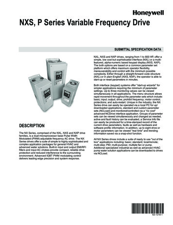
NXS, P Series Variable Frequency DriveSUBMITTAL SPECIFICATION DATANXL, NXS and NXP drives, ranging from 1 to 800 HP, offer asimple, low cost but sophisticated interface (NXL) or a multifeatured, alpha-numeric based keypad display (NXS, NXP).The both options are based on a common parameter setplatform which offers maximum operator flexibility,maneuverability and control with the minimum possiblecomplexity. Either through a straight-forward code structure(NXL) or in plain English (NXS, NXP), the operator is able tostart-up or reset parameters in minutes.DESCRIPTIONThe NX Series, comprised of the NXL, NXS and NXP drivefamilies, is a dual-microprocessor base Pulse WidthModulated (PWM) adjustable frequency AC drive. The NXSeries drives offer a suite of simple to highly sophisticated andcomplex application packages for general HVAC andadvanced water solutions. Built-in input and output EMI/RFIfilters and input AC chokes provide compact, reliable driveprotection and reduced interference to the surroundingenvironment. Advanced IGBT PWM modulating controldelivers leading edge precision and system response.Both interface (keypad) systems offer "start-up wizards" forsimpler applications requiring the minimum of parametersettings. Up to three monitoring values can be viewedsimultaneously in all applications. The menu structure allowsrapid movement throughout the parameter sets which include:basic; input; output; drive; prohibit frequency; motor control;protections; and auto-restart. Unique in the industry, the NXSeries drive can easily be operated via a local PC for up/downloaded applications, standard and custom parametersets (NCLoad) and monitored/controlled via a "no cost"advanced NCDrive interface application. Groups of parametersets can be viewed simultaneously and changed as needed,active and fault history can be evaluated, a Service Info filecan easily be produced for a time-stamped record of thecurrent drive parameters, faults as well as hardware andsoftware profile information. In addition, up to eight drive ormotor parameters can be viewed "real time" and trendinginformation saved via a snap-shot function.All NX Series drives include a suite of ready to use "out of thebox" applications including: basic; standard; local/remote;multi-step; PID; multi-purpose; multiple fan or pump.Additional specialized industrial as well as advanced HVACpump water solution applications can be downloaded to drivesvia NCLoad.63-1319-1
NXS, P SERIES VARIABLE FREQUENCY DRIVEFEATURES Standard Features UL, cUL labeled and CE markedEMI/RFI Filter - Input & OutputStart-Up WizardFault & Diagnostics AssistanceFault History NXS, P - max 30 stored faultsReal Time Clock function - PC or manual input mode— Day, Month, Year; Hour, Minute, Second7 prepackaged applications: Basic; Standard; Local/Remote;Multi-Step; PID Control; Multi-Purpose; Multiple Fan and PumpNCLoad & NCDrive PC no charge software for: drive access foroperation, monitoring up to 8 variables, diagnostics/faults, servicerecordVFD & Keypad Parameter Backup (upload/download)Full Graphic and Multilingual Display— Operator Control, Parameter Set-Up, Control locationdesignation— Data Display:— Output Frequency (Hz)— Frequency reference (Hz)— Motor Speed (RPM calculated)— Motor Current (Measured)— Motor Torque (Calculated)— Motor Power (Calculated)— Motor Voltage (Calculated)— DC Link Voltage (Measured)— Heatsink Temperature (Measured)— Motor Temperature (Calculated)— Analogue Inputs 1, 2, 3, 4— Digital Inputs 1, 2, 3— Digital Inputs 4, 5, 6— PID Reference, Actual Value, Error Value, Output— Multiple Monitoring (3) values— Fault Text— User Selectable Engineering UnitsTwo (2) Programmable Analog InputsSix (6) Programmable Digital InputsOne (1)) Programmable Analog OutputTwo (2) standard Programmable Relay OutputsFive (5) Additional AI/AO, DI/DO, RO BoardsAdjustable Filters on Analog Inputs and OutputsMathematical Functions on Analog Reference SignalsAll Control Inputs Isolated from Ground and PowerOptional Communication Protocols— RS-485 Modbus & Johnson Controls N2— Lonbus— BACnet— Profibus & Device NetInput Speed Signals— Current 0 (4) to 20 mA— Voltage 0 (2) to 10 VDC— Increase/Decrease Reference Contacts(Floating Point)— Serial CommunicationsStart/Stop— 2 Wire (Dry Contact Closure)— Output Frequency Supervision— Application of Reference Signal (Sleep/Wake-Up)— Serial CommunicationsStart Functions— Ramp, Flying Start,— Automatic Torque Boost (U/f optimization)— Auto Restart Selectable by Ramp or Flying Start (Reset) Customer Selectable and— Adjustable (Over/Under V, Over/Under C, AI, Motor Temp,Underload)63-1319—12 Stop Functions— Ramp or Coast to Stop— Emergency Stop— DC Braking / Hold at Stop— Flux BrakingAcceleration/Deceleration— Two (2) sets of Independently Ramps— Linear, Squared or Adjustable 'S' CurveSeven HVAC and Open Use Prepackaged ApplicationsSeparate Safeties (2) and Run Permissive InputsOverride Input (Fire Mode)Timer FunctionsUp to fifteen (15) Preset Speeds (Multi-Step Application)Supervision FunctionsAdjustable Current LimitElectronic ReverseAutomatic Extended Power Loss Ride Through (Selectable)Programmable Maximum Frequency to 320 Hz, 7200 Hz UtilizingPre-packaged High Speed ApplicationPID Control— Two (2) Integral Independent Programmable PID— Setpoint Controllers (Process and External)— External Selection between Two (2) Sets of Process— PID Controller Parameters— PID Sleep/Wake-UpMotor Control Features— Scalar (V/Hz) and Vector Modes of Motor Control— V/Hz Shapes— Linear— Squared— Energy Optimization— IR Compensation— Slip Compensation— Three (3) Critical Frequency Lockout BandsPreprogrammed Protection Circuits— Overcurrent— Short Circuit— Ground Fault— Overvoltage— Undervoltage— Input Phase Loss— Output Device (IGBT) Overtemperature— Adjustable Current Limit Regulator— UL508C approved Electronic Motor Overload (I2T)Programmable Fault Functions for Protection Include— Loss of Analog Input— Panel Loss— External Fault— Motor Thermal Protection— Stall— Underload— Motor Phase Loss— Ground Fault3% AC Choke built-into all modelsOPTIONAL FEATURES Five additional I/O boards (various AI, AO, DI, DO, ROcombinations)Available Fieldbus Protocol Option Boards:LonWorks, BACnet, RS485-MODbus & N2, Profibus and DeviceNetAdvanced water solutions no charge application softwareFan Replacement Kit
NXS, P SERIES VARIABLE FREQUENCY ControlCharacteristicsInput voltage Uin208 240V; 380 500V; 525 690V; –10% 10%Input frequency45 66 HzConnection to mainsOnce per minute or less (normal case)Output voltage0—UinContinuous output currentIh: Ambient temperature max. 122ºF (50 C),overload 1.5 x Ih (1 min./10 min.)Il: Ambient temperature max. 104 F (40 C),overload 1.1 x Il (1 min./10 min.)Starting torqueIs for two seconds, torque motor dependentPeak currentIs for 2 s every 20 sOutput frequency0 320 Hz (NXS); 7200 Hz (Special)Frequency resolution0.01 Hz (NXS); Application dependent (NXP)Control methodFrequency control U/f Open Loop Sensorless Vector ControlClosed Loop Frequency ControlClosed Loop Vector Control (NXP only)Switching frequency(see parameter 2.6.9)NX B:NX A:Up to and including NX 0061:1 16 kHz; Factory default 10 kHz From NX 0072:1 10 kHz; Factory default 3.6 kHz1 6 kHz; Factory default 1.5 kHzNX C:Frequency reference Analogue Resolution 0.1% (10-bit), accuracy 1% Resolution 0.01 Hzinput Panel referenceField weakening pointAmbientConditionsEMC (at defaultsettings)Safety8 320 HzAcceleration time0.1 3000 secDeceleration time0.1 3000 secBraking torqueDC brake: 30% * Tn (without brake option)Ambient operating temperature 14 F (-10 C) (no frost) 122 F (50 C): Ih 14 F (-10 C)(no frost) 104 F (40 C): IlStorage temperature–104 F 158 FRelative humidity0 to 95% RH, non-condensing, non-corrosive, no dripping waterAir quality:-chemical vapors-mechanical particlesIEC 721-3-3, unit in operation, class 3C2IEC 721-3-3, unit in operation, class 3S2Altitude100% load capacity (no derating) up to 3147 feet;-1% derating for each 327 ft above 3147 ft.; max. 9843 ftVibrationEN50178/EN60068-2-65 150 HzDisplacement amplitude 0,04 in (peak) at 3 15.8 Hz Max accelerationamplitude 1 G at 15.8 150 HzShockIEC50178, IEC60068-2-27UPS Drop Test (for applicable UPS weights) Storage and shipping: max 15G, 11 ms (in package)Enclosure classIP21/NEMA1 standard in entire kW/HP rangeIP54/NEMA12 option in entire kW/HP rangeNote: Keypad installation required for IP54ImmunityFulfil all EMC immunity requirementsEmissionsEMC level H: IEC 61800-3 (1996) A11 (2000)(1st environment, restricteduse); IEC 61000-6-4 EMC level L: IEC 61800-3 (1996) A11 (2000)(2ndenvironment)EN 50178 (1997), IEC 60204-1 (1996), IEC 60950(2000, 3rd edition) (as relevant), CE, UL, CUL, FI, GOSTR, IEC 61800-5; (see unit nameplate for more detailed approvals)363-1319—1
NXS, P SERIES VARIABLE FREQUENCY DRIVEControlConnectionsProtectionsAnalogue input voltage0 10V, Ri 200kÙ, (–10V 10V joystick control) Resolution 0.1%,accuracy 1%Analogue input current0(4) 20 mA, Ri 250Ù differentialDigital inputs (6)Positive or negative logic; 18 30VDCAuxiliary voltage 24V, 15%, max. 250mAOutput reference voltage 10V, 3%, max. load 10mAAnalogue output0(4) 20mA; RL max. 500Ù; Resolution 10 bit; Accuracy 2%Digital outputsOpen collector output, 50mA/48VRelay outputs2 programmable change-over relay outputs (1 NO/NC; 1 NO)Switching capacity: 24VDC/8A, 250VAC/8A,125VDC/0.4AMin. switching load: 5V/10mA1 thermister input for motor overtemperature warningOvercurrent protectionTrip limit 4.0*IH instantaneouslyOvervoltage protectionUndervoltage protectionNX 2: 437VDC;NX 5: 911VDC;NX 6: 1200VDC NX 2: 183VDC;NX 5: 333VDC;NX 6: 460 VDCGround fault protectionIn case of ground fault in motor or motor cable, only the frequency drive isprotectedMains supervisionTrips if any of the input phases is missingMotor phase supervisionTrips if any of the output phases is missingUnit overtemperatureprotectionYesMotor overload protectionYesMotor stall protectionYesMotor underload protectionYesShort-circuit protection of 24V Yesand 10V reference voltages63-1319—14
NXS, P SERIES VARIABLE FREQUENCY DRIVEFault codesThe fault codes, their causes and correcting actions arepresented in the table below. The faults 37, 38, 39 are A faultsonly. The following faults for which you can be programdifferent responses in the application are: 3, 9, 10, 11, 15, 16,17, 42, 50 indicated by *. See parameter group Protections.FaultcodeFaultNOTE: When contacting distributor because of a fault condition, always write down all text and codes on the keypad display.Possible CauseCorrecting MeasuresOvercurrentFrequency drive has detected too high a current( 4*In) in the motor cable: - sudden heavy loadincrease - short circuit in motor cables- unsuitable motorOvervoltageThe DC-link voltage has exceeded the limits defined Make the deceleration time longer. Use brakein Table 4-2. - too short a deceleration time - highchopper or brake resistor (available asovervoltage spikes in supplyoptions)Ground Fault*Current measurement has detected that the sum ofmotor phase current is not zero.- insulation failure in cables or motorCheck motor cables and motor.Charging switchThe charging switch is open, when the STARTcommand has been given. - faulty operation component failureReset the fault and restart. Should the faultre-occur, contact your nearest distributor.Emergency stopStop signal has been given from the option board.Saturation tripVarious causes, e.g. defective componentSystem fault-component failure -faulty operation Note exceptional Reset the fault and restart. Should the faultfault data record, see 7.3.4.3.re-occur, contact your nearest distributor.Under voltage*DC-link voltage is under the voltage limits defined in. In case of temporary supply voltage break- most probable cause: too low a supply voltagereset the fault and restart the frequency drive.- frequency drive internal faultCheck the supply voltage. If it is adequate, aninternal failure has occurred. Contact yournearest distributor.10Input linesupervision*Input line phase is missing.Check supply voltage and cable.11Output phasesupervision*Current measurement has detected that there is nocurrent in one motor phase.Check motor cable and motor.Brake choppersupervision*no brake resistor installed brake resistor is brokenbrake chopper failureCheck brake resistor. If the resistor is ok, thechopper is faulty. Contact your nearestdistributor.Frequency driveunder-temperatureHeatsink temperature is under 14 F (– 10 C)Frequency driveovertemperatureHeatsink temperature is over 194 F (90 C).Overtemperature warning is issued when theheatsink temperature exceeds 185 F (85 C).Check the correct amount and flow of coolingair. Check the heatsink for dust. Check theambient temperature. Make sure that theswitching frequency is not too high in relationto ambient temperature and motor load.15Motor stalled*Motor stall protection has tripped.Check motor.16Motorovertemperature*Motor overheating has been detected by frequency Decrease the motor load. If no motordrive motor temperature model. Motor is overloaded. overload exists, check the temperaturemodel parameters.17Motor underload*Motor underload protection has tripped.22EEPROMParameter save fault23checksum faultFaulty operation component failure123567891213145Check loading. Check motor.Check cables.Cannot be reset from the keypad. Switch offpower. DO NOT RE-CONNECT POWER!Contact factory. If this fault appearssimultaneously with Fault 1, check motorcables and motor63-1319—1
NXS, P SERIES VARIABLE FREQUENCY DRIVEFaultcode2526FaultPossible CauseCorrecting MeasuresMicroprocessorwatchdog faultFaulty operation component failureReset the fault and restart. Should the faultre-occur, contact your nearest distributor.Start-up preventedStart-up of the drive has been prevented.Cancel prevention of start-up.Thermistor faultThe thermistor input of option board has detectedincrease of the motor temperatureCheck motor cooling and loading Checkthermistor connection (If thermistor input ofthe option board is not in use it has to beshort circuited)Fan coolingCooling fan of the frequency drive does not start,when ON command is givenContact your nearest distributor.CAN buscommunicationSent message not acknowledged.Ensure that there is another device on thebus with the same configuration.Control unitNXS Control Unit can not control NXP Power Unitand vice versaChange control units37Device changed(same type)Option board or control unit changed. Same type ofboard or same power rating of drive.Reset Note: No fault time data record!38Device added(same type)Option board or drive added. Drive of same powerrating or same type of board added.Reset Note: No fault time data record!39Device removedOption board removed. Drive removed.Reset Note: No fault time data record!Contact your nearest distributor.2932343640Device unknownUnknown option board or drive.IGBT temperatureIGBT Inverter Bridge overtemperature protection has Check loading. Check motor size.detected too high a short term overload currentBrake resistorovertemperature*Brake resistor overtemperature protection hasdetected too heavy brakingSet the deceleration time longer. Useexternal brake resistor.Encoder faultNote the exceptional Fault data record.1 Encoder 1 channel A is missing2 Encoder 1 channel B is missing3 Both encoder 1 channels are missing4 Encoder reversedCheck encoder channel connections.Check the encoder board.Current at the analogue input is 4mA.- control cable is broken or loose- signal source has failedCheck the current loop circuitry.50Analog input Iin 4mA (selectedsignal range4 to 20 mA)*51External faultDigital input fault.52KeypadThe connection between the control key-pad and the Check keypad connection and possiblecommunication fault freq. drive is broken.keypad cable.414243535456Fieldbus faultThe data connection between the fieldbus Masterand the fieldbus board is broken.Check installation. If installation is correctcontact your nearest distributor.Slot faultDefective option board or slotCheck board and slot. Contact your nearestdistributor.PT100 board temp.faultTemperature limit values set for the PT100 boardparameters have been exceededFind the cause of temperature rise63-1319—16
NXS, P SERIES VARIABLE FREQUENCY DRIVEFault time data recordThe data available are:When a fault occurs the information described above isdisplayed. By pushing the right arrow menu button it ispossible to view the Fault time data record menu indicated byT.1.T.13.In this menu, some selected important data valid at the time ofthe fault are recorded. This feature is intended to help the useror the service person to determine the cause of fault.T.1Counted operation days(Fault 43: Additional code)dT.2Counted operation hours(Fault 43: Counted operation days)hh:mm:ss(d)T.3Output frequency(Fault 43: Counted operation hours)Hz(hh:mm:ss)T.4Motor currentAT.5Motor voltageVT.6Motor power%T.7Motor torque%T.8DC voltageVT.9Unit temperature FT.10Run statusT.11DirectionT.12WarningsT.130-speedREAL TIME RECORDIf real time is set to run on the frequency drive the data itemsT1 and T2 will appear as follows:T.1Counted operation days yyyy-mm-ddT.2Counted operation hourshh:mm:ss,sssVFD CONTROL KEYPADThe frequency drive is operable through the nine pushbuttons of the control keypad. Furthermore, the buttons servethe purposes of parameter setting and value monitoring.The keypad is detachable and isolated from the input linepotential.Fig. 1. Control KeypadThe control keypad is the link between the frequency driveand the user. The NX control keypad features analphanumeric display with seven indicators for the Run status(RUN,, READY, STOP, ALARM, FAULT) and threeindicators for the control place (I/O term/ Keypad/BusComm).There are also three Status Indicator LEDs (green - green red).The control information, i.e. the number of menu, descriptionof menu or the displayed value and the numeric informationare presented on three text lines.7Fig. 2. Keypad indicationsDrive status indicationsThe drive status indications tell the user what the status of themotor and the drive is, and whether the motor control softwarehas detected irregularities in motor or frequency drivefunctions.63-1319—1
NXS, P SERIES VARIABLE FREQUENCY DRIVE Illuminates when the drive is running. Blinks whenRUN Motor is running; Blinks when the stopthe STOP button has been pushed and the drive is rampingdown.command has been given but the frequency is still rampingdown. Illuminates when unsafe operating conditions were Indicates the direction of motor rotation.encountered due to which the drive was stopped (Fault Trip).Simultaneously, the drive status indicator FAULT blinks on thedisplay and the fault description can be seen, see ActiveFaults.STOP Indicates that the drive is not running.READY Lights when AC power is on. In case of a trip,the symbol will not light up.ALARM Indicates that the drive is running outside aKEYPAD MAIN MENU AND SUBMENUNAVIGATIONFor more information on the menus, see the User Manual.certain limit and a warning is given.Navigation on the control keypadFAULT Indicates that unsafe operating conditionsThe data on the control keypad are arranged in menus andsubmenus. The menus are used for example for the displayand editing of measurement and control signals, parametersettings, reference values and fault displays. Through themenus, the contrast of the display can be adjusted.were encountered due to which the drive was stopped.Control place indicationsThe symbols I/O term, Keypad and Bus/Comm (see Fig. 2)indicate the choice of control place made in the Keypadcontrol menu (M3).LOCATIONI/O term I/O terminals are the selected control place;i.e. START/STOP commands or reference values etc. aregiven through the I/O terminals.DESCRIPTIONNUMBER OF ITEMS AVAILABLEITEM VALUEKeypad Control keypad is the selected control place;i.e. the motor can be started or stopped, or its referencevalues etc. altered from the keypad.Fig. 3. MenusBus/Comm The frequency drive is controlled througha fieldbus.Status LEDsThe status LEDs light up in connection with the READY, RUNand FAULT drive status indicators.The first menu level consists of menus M1 to M7 and is calledthe Main menu. The user can navigate in the main menuusing the Browser buttons up and down. The desiredsubmenu can be entered from the main menu using the Menubuttons. When there still are pages to enter under thecurrently displayed menu or page, an arrow () can beseen in the lower right corner of the display and by pressingthe right arrow menu button, the next menu level can bereached.The control keypad navigation chart is shown on the nextpage. Please note that the menu M1 is located in the lower leftcorner. From there it is possible to navigate your way up to thedesired menu using the menu and browser buttons. Illuminates with the AC power connected to thedrive. Simultaneously, the drive status indicator READY is litup.63-1319—1M137558
NXS, P SERIES VARIABLE FREQUENCY DRIVEFig. 4. Keypad Navigation Chart963-1319—1
NXS, P SERIES VARIABLE FREQUENCY DRIVEMonitoring menu (M1)The monitoring menu can be entered from the main menu bypushing the Right arrow menu button when the locationindication M1 is visible on the first line of the display. How tobrowse through the monitored values is presented in Fig. 5.Fig. 5. Monitoring menuThe monitored signals carry the indication V#.# and they arelisted in the Table below. The values are updated once every0.3 seconds. This menu is only for signal checking. Thevalues cannot be altered here.Table 1. Monitored signalsCodeSignal nameUnitDescriptionV1.1Output frequencyHzV1.2Frequency referenceHzFrequency to the motorV1.3Motor speedrpmCalculated motor speedV1.4Motor currentAMeasured motor currentV1.5Motor torque%Calculated actual torque/nominal torque of the unitV1.6Motor power%Calculated actual power/nominal power of the unitV1.7Motor voltageVCalculated motor voltageV1.8DC-link voltageVMeasured DC-link voltageV1.9Unit temperatureºFHeat sink temperatureV1.10Motor temperature%Calculated motor temperatureV1.11Voltage inputVAI1V1.12Current inputmAAI2V1.13DIN1, DIN2, DIN3Digital input statusesV1.14DIN4, DIN5, DIN6Digital input statusesV1.15DO1, RO1, RO2V1.16Analogue output currentV1.17Multi monitoring itemsDigital and relay output statusesmAAO1Displays three selectable monitoring values.In the Keypad Controls Menu, it is possible to choose thecontrol place, edit the frequency reference and change thedirection of the motor. Enter the submenu level with the rightarrow menu button.SELECTION OF CONTROL PLACEThere are three different places (sources) which the frequencydrive can be controlled from. For each control place, adifferent symbol will appear on the alphanumeric display:63-1319—110Change the control place by entering the edit mode with theright arrow menu button. The options can then be browsedthrough with the Browser buttons. Select the desired controlplace with the Enter button.
NXS, P SERIES VARIABLE FREQUENCY DRIVEKEYPAD REFERENCEThe keypad reference submenu displays and allows theoperator to edit the frequency reference. The changes willtake place immediately. This reference value will not,however, influence the rotation speed of the motor unless thekeypad has been selected as the active control place.NOTE: The maximum difference between the output frequency and the keypad reference is 6 Hz.The application software monitors the keypad frequencyautomatically.KEYPAD DIRECTIONThe keypad direction submenu displays and allows theoperator to change the rotating direction of the motor. Thissetting will not, however, influence the rotation direction of themotor unless the keypad has been selected as the activecontrol place.See Fig. 6 for how to change the rotation direction.Fig. 6. Selection of control placeSTOP BUTTON ACTIVATEDBy default, pushing the STOP button will always stop themotor regardless of the selected control place. You candisable this function by giving parameter 3.4 the value 0. If thevalue of this parameter is 0, the STOP button will stop themotor only when the keypad has been selected as the activecontrol place.NOTE: Information on controlling the motor with the keypadis in the User Manual.NOTE: There are some special functions that can be performed when in the M3 menu:the keypad. Copy the frequency reference set elsewhere (I/O,fieldbus) to the panel by keeping the enter button pusheddown for 3 seconds.NOTE: That While in any other than M3 menu these functions will not work.If in a different menu other than M3 menu and try to start themotor by pressing the START button when the keypad is notselected as the active control place an error message KeypadControl NOT ACTIVE will be displayed.System Menu (M6)Select the keypad as the active control place by keeping thestart button pushed down for 3 seconds when the motor isrunning. The keypad will become the active control place andthe current frequency reference and direction will be copied tothe keypad.Select the keypad as the active control place by keeping thestop button pushed down for 3 seconds when the motor isstopped. The keypad will become the active control place andthe current frequency reference and direction will be copied to11The System menu can be entered from the main menu bypushing the right arrow menu button when the locationindication M6 is visible on the display.The controls associated with the general use of the frequencydrive, such as application selection, customized parametersets or information about the hardware and software arelocated under the System menu. The number of submenusand sub pages is shown with the symbol S (or P) on the valueline.63-1319—1
NXS, P SERIES VARIABLE FREQUENCY DRIVETable 2. Functions in the System 1Language S6.2Application selectionBasicApplicationBasic ApplicationStandard Application Local/Remote control Appl.Multi-Step Application PIDControl Application MultiPurpose Control Appl.Pump and Fan Control Appl.S6.3Copy parametersS6.3.1Parameter setsStore set 1Load set 1Store set 2Load set 2Load factory defaultsS6.3.2Load up to keypadAll parametersS6.3.3Load down fromkeypadAll parametersAll but motor parametersApplication parametersP6.3.4Parameter backupS6.4Compare parametersS6.5SecurityNoYes NoS6.5.1PasswordNot used0 Not usedP6.5.2Parameter lockChangeEnabledChange EnabledChange DisabledS6.5.3Start-up wizardNo YesS6.5.4Multi monitoringitemsChange EnabledChange DisabledS6.6Keypad settingsP6.6.1Default pageP6.6.2Default page/Operating menuP6.6.3Time-out time065535P6.6.4Contrast031P6.6.5Backlight timeAlways 65535S6.7Internal brake resistorP6.7.2Fan controlP6.7.3HMI acknowledge.time-outP6.7.4HMI number of retries 1min102005000msTotal countersC6.8.1.1MWh counterC6.8.1.2Power On daycounterC6.8.1.3Power On hourscounterConnectedNot connectedConnectedContinuousContinuous Temperature200105System informationS6.8.163-1319—13018Hardware settingsP6.7.1S6.8skWhhh:mm:s s12
NXS, P SERIES VARIABLE FREQUENCY DRIVECodeFunctionS6.8.2Trip countersT6.8.2.1MWh counterT6.8.2.2Clear MWh tripcounterT6.8.2.3Operating days tripcounterT6.8.2.4Operating hours tripcounterT6.8.2.5Clear operating :mm:ssSoftware infoS6.8.3.1Software packageS6.8.3.2System softwareversionS6.8.3.3Firmware interfaceS6.8.3.4System loadS6.8.4ApplicationsS6.8.4.#MinName of applicationD6.8.4.#.1 Application IDD6.8.4.#.2 Applications: VersionD6.8.4.#.3 Applications:Firmware interfaceS6.8.5HardwareI6.8.5.1Info: Unit powerkWI6.8.5.2Info: Unit voltageVI6.8.5.3Info: Brake chopperI6.8.5.4Info: Brake resistorS6.8.6Expander boards1363-1319—1
NXS, P SERIES VARIABLE FREQUENCY DRIVECONTROL TERMINAL SIGNALSTerminalSignalTechnical Information1 10 VrefReference voltageMaximum current 10 mA2AI1 Analogue input,voltage or current3GND/AI1–Analogue input commonSelection V or mA with jumper block X1 (see page 68):Default: 0– 10V (Ri 200 kÙ)(-10V . 10V Joy-stick control, selected with a jumper)0– 20mA (Ri 250 Ù) Differential input if not connected to ground;Allows 20V differential mode voltage to GND4AI2 Analogue input,voltage or current5GND/AI2–Analogue input common624 Vout(bidirectional)24V auxiliary voltage 15%, maximum current 250mA (all boards total);150mA (fromsingle board); Can also be used as external power backup for thecontrol unit (and fieldbus)7GNDI/O groundGround for reference and controls8DIN1Digital input 1Ri min. 5k.9DIN2Digital input 210DIN3Digital input 311CMADigital input common A for DIN1,DIN2 and DIN3.Must be connected to GND or 24V of I/O terminal or to external24V or GNDSelection with jumper block X3 (see page 68):1224 Vout(bidirectional)24V auxiliary voltageSame as terminal #613GNDI/O groundSame as terminal #714DIN4Digital input 4Ri min. 5k.15DIN5Digital input 516DIN6Digital input 617CMBDigital input common B for DIB4,DIB5 and DIB6Must be connected to GND or 24V of I/O terminal or to external24V or GNDSelection with jumper block X3 (see page 68):18AO1 Analogue signal ( output)19AO1–Analogue output commonOutput signal range:Current 0(4)–20mA, RL max 500Ù or Voltage 0—10V, RL 1k.Selection with jumper block X6 (see page 68):20DO1Open collector outputMaximum Uin 48VDC Maximum current 50 mASelection V or mA with jumper block X2 (see page 68):Default: 0– 20mA (Ri 250 Ù)0– 10V (Ri 200 kÙ)(-10V . 10V Joy-stick control, selected with a jumper)Differential input if not connected to ground;Allows 20V differential mode voltage to GNDControl I/O Terminal Signals On Basic Relay Board al InformationRelay output 1Switching capacityMin. switching loadRO2/1Relay output 2Switching capacityRO2/226Min. switching load28TI1 29TI1-63-1319—1Thermistor input1424VDC/8A250VA
IEC 721-3-3, unit in operation, class 3C2 IEC 721-3-3, unit in operation, class 3S2 Altitude 100% load capacity (no derating) up to 3147 feet;-1% derating for each 327 ft above 3147 ft.; max. 9843 ft Vibration EN50178/EN60068-2-6 5-150 Hz Displacement amplitude 0,04 in (peak) at 3-15.8 Hz Max acceleration amplitude 1 G at 15.8-150 Hz Shock