Transcription
Capacitor AssemblyAutomationTeam 6:Marissa ForeitKyler KazmierskiFolaranmi AdenolaOlayinka OladosuSponsor: Mr. WalkerAdvisor: Dr. MooreProfessor: Dr. Shih4/13/2017
Presentation Outline Introduction and Background InformationProduct SpecsProblem Statement/Goal StatementKey Assembly StepsDesign ProcessImproved Process with Updated OperationsTime ImprovementsProposed Floor LayoutChallenges FacedFuture WorkBudget ReportFOLARANMI ADENOLA2
Introduction and Background Information Unison Industries Subsidiary of GESpecial in electrical components for jet engines, ignition systems and generators80% of jet engines are installed with ignition systems produced by UnisonIndustries Capacitor Assembly Automation Making a manual process automated in order to reduce assembly time Options of fully automatic versus semi automatic Fully automatic requires no operatorSemi automatic requires some use of the operatorFOLARANMI ADENOLA3
Product Specs 4 individual sections Layer of insulation paper and double sided tape inbetween Insulation material wrapped around wholeFigure 1assembly Maximum dimensions: 4.25”H x 2.6”L x 1.38”WFigure 2FOLARANMI ADENOLA4
Problem Statement/ Project GoalProblem Statement The current process of assembling capacitors takes approximately 27 min The goal is to reduce this time to 15 minThe assembly process has multiple steps involvedEach step has been analyzed in order to choose the best ones to improvewith either automation or a new manual processProject Goal Goal Statement: To create a streamline process to reduce the overallassembly time by adding some automation and updating some currentmanual processesFOLARANMI ADENOLA5
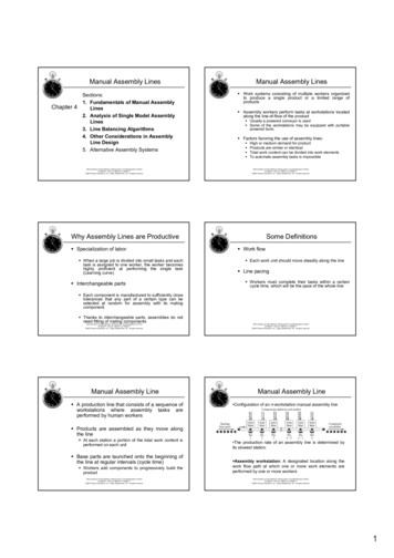
Key Assembly Steps1. Place a layer of double sided tape on each capacitor ImprovedAutomated Step Improved ManualStep2. Stack the 4 individual capacitors3. Solder the electrical tabs4. Insert the lead wires and form the safety loops5. Wrap the capacitor stack with insulation paper6. Wrap pieces of tape around the insulation paper7. Final dimension checkFigure 3MARISSA FOREIT6
Design StepsCreateconceptualdesigns foreachupdated stepAssembleprototypesCreate 2Dprints andmachine thepartsCreate 3Ddrawings foreach designRedesignMARISSA FOREIT7
Updated Assembly Process:Tape Rolling18”10”Figure 4 Powered by motor Tape (blue) rolls onto individual capacitors Roller (green) rolls behind the tape to ensure tape sticksSaves time by: Reducing number of times the layer on the tape needs to be pulled back Guided slots make the cutting process easier and more efficientMARISSA FOREIT8
Tape Rolling Con’tFigure 5 After tape is placed on capacitors, operator will peel back sealing layer After this, the operator will cut the tape in between the sections Scissors will be guided by grooves in the plateMARISSA FOREIT9
Tape Rolling to Stacking9”18”Figure 6Figure 7MARISSA FOREIT10
StackingFigure 8Figure 9 L-Gauge will guide the stacking of the capacitors Saves time by making the capacitors easier toalignMARISSA FOREIT11
Stacking to Soldering/Attaching Lead Wire After stacking, the operator will move the capacitor to the next workstation At this work station, a second operator will began soldering the tabs,attaching lead wires and forming the safety loops These are intricate processes and will not be updatedMARISSA FOREITFigure 1012
Soldering/Attaching Lead Wire to InsulationPaper Wrapping After soldering, operator will bring the capacitor to the next workstation The next operator will then load the capacitor into the paper wrappingmachine to begin that processMARISSA FOREIT13
Paper Wrapping/Tape Wrapping15”15”Figure 11Figure 12KYLER KAZMIERSKI14
Paper RollFigure 13Figure 14KYLER KAZMIERSKIFigure 1515
Paper Wrapping to Dimension Check Immediately after wrapping the paper and tape, the operator will unload the capacitorand place it into the gauge block for the final dimensional check Maximum dimensions are 1.38” x 2.60” x 4.25”Saves time by checking all dimensions at onceFigure 16Figure 17KYLER KAZMIERSKIFigure 1816
Original Designs vs Final DesignsTape RollerFigure 19Figure 20L-GaugeFigure 22Figure 21KYLER KAZMIERSKI17
Original Designs vs Final DesignsPaper WrapperFigure 23Figure 24Gauge BlocksFigure 25Figure 26Figure 27KYLER KAZMIERSKI18
Estimated TimesAssembly StepCurrent TimeImproved TimeTape Roller2 min 15 sec35 secStacking25 sec12 secPaper Wrapping2 min 50 sec1 min 25 secDimension Check1 min 4 sec15 secKYLER KAZMIERSKI19
Proposed Lean Floor LayoutWork Station #1Work Station #2Work Station #3Operator #1Operator #2Operator #324”Soldering/LeadWiresPaperWrapperL-GaugeTape Roller36”Legend:Product Flow36”GaugeBlockAutomatedUpdated Manual36”KYLER KAZMIERSKI20
Challenges Faced Creating the initial designs Understanding the current process well enough to improve itRedesigning the L-Gauge and Gauge Block to make them more user friendlyRedesigning the Tape Roller to make the parts machinableFinding a machine shop to create the parts for the Paper Wrapper 3D printed most of the partsRedesigning the tape roller to prevent the roller arms from swingingOLADOSU OLAYINKA21
Gantt ChartOLADOSU OLAYINKA22
Future Work Add motors to tape roller and wrapping design Automate the tape wrapping Possibly automate the stacking design with a robot Update the remaining assembly stepsFigure 28OLADOSU OLAYINKA23
Budget ReportOLADOSU OLAYINKA24
Budget Pie 27.57OLADOSU OLAYINKA25
Summary The overall assembly process was analyzed to find the best steps to improveDesigns were created for 4 of the steps 2 will become automated and 2 are manualAll 4 steps reduced original assembly timeMany challenges were faced Delayed getting the prints to the shopFinding a shop to make some of the partsOLADOSU OLAYINKA26
References Kevin Walker, Assembly Steps Handout27
Questions?28
The assembly process has multiple steps involved Each step has been analyzed in order to choose the best ones to improve with either automation or a new manual process Project Goal Goal Statement: To create a streamline process to reduce the overall assembly time by adding some automatio
