Transcription
Roof-Floor Truss manual7/31/0810:42 AMPage 1ROOF & FLOOR TRUSSESA MANUAL FOR ARCHITECTS AND ENGINEERSDESIGN INFORMATIONTECHNICAL DATAAPPROVALSSPECIFICATION & DETAILSwww.mii.comTM
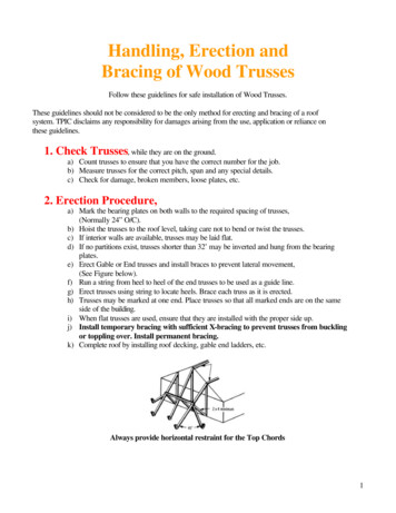
Roof-Floor Truss manual7/31/0810:42 AMPage 2 MITEKPRODUCTS& SERVICESHeadquartered in St. Louis, Missouri,For more than 35 years MiTek companies have developed and refined their connector plates into the state-MiTek Industries, Inc. is the leadingof-the-art products they are today. consistent anddependable!supplier of connector plates, trussWith MiTek you’re assured of the best quality. MiTekmanufacturing equipment, designconnector plates are manufactured under strictquality control and undergo extensive testing in oursoftware and engineering servicesR & D facility.MiTek’s connector plates meet or exceed allfor the worldwide componentbuilding code and industry association requirements.Acceptances include ICC-ES, Florida-Dade County andindustry.LA City.MiTek also offers the very best in framing layout andengineering software for roof and floor trusses, as wellas wall panel design. These programs provide ourfabricators with fast and accurate layout and designcapabilities.Our engineering department is available to reviewand seal our customers’ designs. With offices in NorthCarolina, Missouri, Florida and California, MiTek’sprofessional engineers can furnish sealed engineeringfor all 50 states!Look to a MiTek fabricator for the best the industry hasto offer! This brochure reviews the benefits of usingwood roof and floor trusses, but MiTek fabricators alsooffer a full line of builders hardware and a complementof other building components including wall panels andsteel framing.At MiTek, we are committed to providing the bestproducts and services in the industry and will continueour tradition of customer support.TM
Roof-Floor Truss manual7/31/0810:43 AMPage 3CONNECTORPLATESBRACING IGNSOFTWAREENGINEERINGSERVICESW W W. M I I . C O M1
Roof-Floor Truss manual7/31/0810:43 AMPage 4WHY USE WOOD TRUSSES?TABLE OF CONTENTSCONTRACTORS AND BUILDERS KNOW.1 OVERVIEWADVANTAGES2 WHY USE WOODTRUSSES?INSTALLATION4 HANDLING,Contractors and builders know thata MiTek engineered roof or floortruss ensures quality and efficiency.INSTALLATION ANDBRACINGMiTek Trusses Save MoneyPRODUCTS5 BRACING &RESTRAININGTRUSS TYPES6 TYPICAL TYPESBecause costs are known in advance,there’s no guesswork. Your siteerection time is greatly reduced anddollar losses from job site materialshortages and pilferage are eliminated.CONSTRUCTION DETAILS8 FLOOR TRUSSES10 CANTILEVERS, JACKSMiTek Trusses Are ReliableEvery MiTek truss has been individu-11 STAIRWAYS ANDSTAIRWELLSMISCELLANEOUSally designed and that design ischecked and approved by licensedengineers for structural adequacy.12 ARCHITECTURALSPECIFICATIONSMITEK TRUSSES Are Versatile12 CONSTRUCTIONDOS & DON’TSMiTek trusses provide more design12 RECOMMENDATIONSAND LIMITATIONSventional framing. Offering numerous13 CONCENTRATED LOADSpresent an economical and struc-14 CODE APPROVALSturally superior method for rapid14 FLOOR DECKING14 MECHANICAL SERVICECLEARANCES15 FIRE RATING16 APPLIED LOADS16 MATERIAL WEIGHTS17 SOUND TRANSMISSION18 MAXIMUM SPANS2flexibility, inside and out, than con-custom design options, our trusseserection.
Roof-Floor Truss manual7/31/0810:43 AMPage 5?FOR THE HOMEOWNER Lower constructioncosts Clearspan flexibilityADVANTAGES OF TRUSSESOVER CONVENTIONALFRAMING More flexibilityin architecturalappearance andfloor plans Easier remodelingFor Architects/DevelopersFor Contractors/Builders Pre-determined, pre-engineeredtruss system Fewer pieces to handle andSavings in design costs-one basicstructural design for shell with minorfloor plan variationspossibilities in movinginterior wallsreduced installation time Better project cost control, withcomponent costs known in advance Wide 3-1/2” nailing surface foreasy floor deck application Better cash flow with earlieroccupancy due to reduced on-site Eliminate notching and boring joistsfor electrical wiring and plumbinglabor Faster shell completion time Using trusses of smaller dimensionlumber, in place of beams andand less in-place cost than 2x8 or2x10 joists columns Greater flexibility in locating additional support requiredReduced HVAC, plumbing, andelectrical subcontractor time on job No column pads to pour, no steelbeams and posts to placeFloor plan freedom in locatinginterior partitions often withoutFactory-manufactured componentsto exact span requirementsplumbing, duct work, and electricalwiringFloor trusses offer better availability Job site material pilferage andcutting waste reduced“TMTMW W W. M I I . C O M3
Roof-Floor Truss manual7/31/0810:43 AMPage 6HANDLING, INSTALLATIONAND BRACING*TEMPORARY BRACING*Reprinted from the “Commentary & Recommendation for Handling, Installing & Bracing,Metal Plate Connected Wood Trusses, HIB-91”, by permission of Truss Plate Institute, Inc.Temporary or installation brac-It is the responsibility of the installer toThe installer should be knowledgeableing is the responsibility of theselect the most suitable method andabout the truss design drawings, trussinstaller. Temporary bracingsequence of installation available toplacement plans, and all notes andshould remain in place as longhim which is consistent with thecautions thereon.as necessary for the safe andowner’s (architectural) plans and speci-acceptable completion of thefications and such other informationroof or floor and may remain inwhich may be furnished to him priorplace after permanent bracing isto installation. Trusses may be installedinstalled.either by hand or by mechanical means.The method generally depends uponthe span of the trusses, their installedheight above grade, and/or the accessibility or availability of mechanicalinstallation equipment (such as acrane or forklift).FIELDASSEMBLYSTORAGEIn some cases, the size or shapeTrusses should be stored in a stableof wood trusses is such thatposition to prevent toppling and/orsome field assembly is required.shifting.The installer is responsible forproper field assembly.During long-term storage, trussesIf trusses are stored horizontally, theshould be protected from the elementsblocking should be eight to ten footComplete details can be found inthe Building Component Safetyin a manner that provides for adequatecenters to prevent lateral bending. If theventilation of the trusses. If tarpaulinstruss bundle is to be stored for moreInformation Guide to Goodthan one week, the solid-blocking,Practice for Handling, Installing,ventilation. If trusses are made withparty, should be at a sufficient heightinterior rated fire retardant lumber,to lessen moisture gain from theextreme care should be taken to limitground.outside exposure.Plate Connected Wood Trusses,Truss Council of America) andTPI (Truss Plate Institute).4used, the ends should be left open forgenerally provided by the receivingRestraining and Bracing of Metalavailable through WTCA (Woodor other water resistant materials are
NRoof-Floor Truss manual7/31/0810:43 AMPage 7MITEK BRACING ANDRESTRAINING PRODUCTSFEATURESSTABILIZER Temporary & permanent lateral bracing Save time and money Eliminate spacing errorsThe Stabilizer accurately spaces roof trusses on 24" and 16" centers with an accuracy The Stabilizerof 1/32". It provides lateral restraints andspaces and bracesin one step withjust a hammerremains as a permanent lateral restraint.The Stabilizer installs as fast as the cranecan set trusses and clips on to ride up withthe truss to the plate line. Eliminatesany activitiesassociated withtemporary bracingMost importantly the Stabilizer saves timeand money. It can reduce installation timeby 45 percent and crane expense by 35 percent. It completely eliminates the time spentThe Stabilizer spaces and braces in onecutting temporary bracing lumber and de-step with just a hammer.nailing and disposing of temporary bracing.MULTI-BRACE ELIMINATOR All-purpose permanent braceFactory-installed T-BracingThe MiTek Multi-Brace is the all-purposeSpeed up roof framing and eliminatebrace that satisfies virtually all of yourfield- applied compression web bracingpermanent truss bracing requirements, yetwith MiTek’s Eliminator . Eliminator is theinstalls more quickly without adding costs.factory-installed alternative to field-appliedThe ultra light Multi-Brace delivers simpleT-bracing and is engineered by MiTek shipping, handling on the ground and in theroof system – assuring you of a safe andaccurately braced roof system. 20/20 software.You can get peace of mind and an engineered component when the T-bracing isIts unique nesting feature allows for substan-installed by your component manufacturertial material savings since it does not requirein their plant. T-bracing, installed in thethe customary one truss or 24" overlap ofright places, can reduce your web bracingconventional lumber bracing.problems before they occur. Factory-installed,engineered web bracingEliminator builds a betterroof system.The Eliminator is the engineered solutionMiTek Multi-Brace, the all purpose brace.to T-bracing installation. It can reduce laborcosts and call backs while improving jobTMsafety.TMW W W. M I I . C O M5
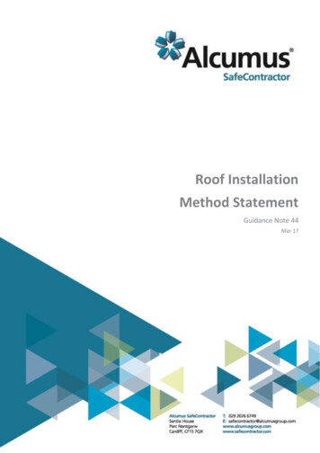
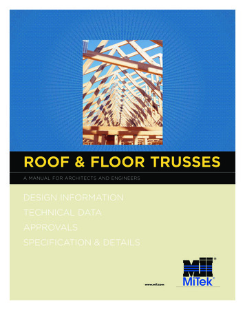
Roof-Floor Truss manual7/31/0810:43 AMPage 8TRUSS TYPESBasic Roof Truss Configurations6KINGPOSTDOUBLE FINKQUEENPOSTDOUBLE HOWEFINKHIPHOWESCISSORSFANMONOPITCHMODIFIED QUEENPOSTCAMBERED
Roof-Floor Truss manual7/31/0810:43 AMPage 9DUAL CATHEDRALBOWSTRINGSLOPING FLATTMSTUBFLATTMW W W. M I I . C O M7
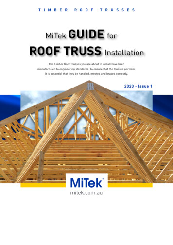
Roof-Floor Truss manual7/31/0810:43 AMPage 10FLOOR TRUSSCONSTRUCTION DETAILSSupport DetailsBottom Chord Bearing onExterior Frame or Masonry WallBottom Chord Bearingon Exterior Frame Wall with Masonry Fascia WallTop chord cut afterinstallation8Intermediate Bearing - Simple Span TrussesIntermediate Bearing - Continuous Floor TrussSpecial Engineering RequiredHeader Beam Pocket Floor Truss Supporting Header BeamSpecial Engineering RequiredIntermediate Bearing Floor Truss Supported by Steel or Wood BeamSpecial Engineering RequiredTop Chord Bearing on Frame WallTop Chord Bearing on Masonry Wall
Roof-Floor Truss manual7/31/0810:43 AMPage 11COMPONENTDESIGNSupport20/20Details ENGINEERINGMITEK JOINT DETAILSExtended Top Chord BearingSpan Limited by EngineeringExtended Top Chord BearingSpan Limited by EngineeringBalcony CantileverSpecial Engineering RequiredLoad-Bearing Wall CantileverSpecial Engineering RequiredDropped Chord Balcony CantileverSpecial Engineering RequiredJOINT DETAILS4" x 4"BlockChord Pre-SpliceTMW W W. M I I . C O M9
Roof-Floor Truss manual7/31/0810:43 AMPage 12FLOOR TRUSSCONSTRUCTION DETAILSSTRONGBACK SUPPORTSCantilever and Jack Details24" Max.LATERAL BRACINGSUGGESTIONS5'-Approx. 72"0"Minimum2x6 “Strongback” lateralsupports should be locatedSection AA - Floor Truss Jackson edge approximately every10 feet along the floor truss.They should be securelyfastened to vertical webs.Floor JoistScab CantileverGirder Floor TrussBlocking behind the verticalweb is recommended whilenailing the strongback. TheNotesstrongbacks should either be Special engineeringrequired for girder floortrussessecured to adjacent partitionwalls or alternate “X” bridgingshould be used to terminate thebracing member.Floor TrussJacksAA Slope for drainage,as required Cantilever span controlledby lumber size, grade anddeflection limitationsBearingWallFloor Cantilevered Perpendicularto Floor Truss SpanGirder Floor TrussTwo 2xRim JoistsFloor TrussJacksCantileveredFloor TrussStrongback Lateral SupportsBearingWall24"Max.Floor Cantilevered Perpendicularand Parallel to Floor Truss Span10
dRoof-Floor Truss manual7/31/0810:43 AMPage 13Stairway and Stairwell DetailsStairwell OpeningwithoutStud WallsSTAIRWAY FRAMINGGirderFloor TrussesBuilt-up Beamwith StrapHangerAlternateLadderFramingHeader BeamPocketStairwell OpeningCarriedby Stud WallHeader Beam withStrap HangerStairwell OpeningPerpendicularto Floor Trusses,Carried byStud WallTypicalBasementStair FramingCross-SectionNotes Framing opening betweenheader beams must usuallybe increased beyond conventional framing opening topermit necessary headroomTM Special engineering required forgirder floor trussesTMW W W. M I I . C O M11
Roof-Floor Truss manual7/31/0810:43 AMPage 14ARCHITECTURALSPECIFICATIONCONSTRUCTION GUIDELINESfor ROOFSDO. Support trusses that are storedhorizontally on blocking toprevent excessive lateral bendingand lessen moisture gain Brace trusses that are storedvertically, to prevent toppling ortippingDON’T Trusses shall be fabricated by a MiTek Delivery, handling, and erection ofMiTek trusses shall be in accordancetruss manufacturer in accordancewith MiTek floor truss engineeringwith the BCSI, Building ComponentspecificationsSafety Information, jointly producedby WTCA and the Truss Plate MiTek engineering design drawings,Institutebearing the seal of the registeredengineer preparing the design, shall Anchorage, permanent bracingbe provided to the project architectand required design loads shall befor his approvalthe responsibility of the building Unload trusses on rough terrainor uneven surfaces, which couldcause damage to the trusses Break banding until installationbegins and the trusses are in astable, horizontal position Lift bundled trusses by the bandsand do not use damaged trussesdesigner Truss designs shall be in accordancewith the latest version of ANSI/TPI1 MiTek truss connector plates areNational Design Standard for Metalmanufactured under rigid qualityPlates Connected Wood Trusscontrol using structural quality steelConstruction, a publication of themeeting ANSI/TPI 1 requirementsTruss Plate Institute, and generallyaccepted engineering practice Walk on trusses that are lyingflat – this is a dangerous practicefor FLOORSDO. Color-code floor truss endsfor correct non-symmetricalinstallations Locate trusses to allow forRECOMMENDATIONS& LIMITATIONS FOR DEPTH, DEFLECTION AND CAMBERplumbing or duct riser clearances Assure that trusses are installedwith a joint located over aninterior bearing Use warning tags on floor trussesto provide proper installationorientation and to warn againstcutting or modifying trussesDON’T Permit stacking of drywall orplywood sheathing duringconstruction on floor trussbalcony cantilevers or at trussmid-span without proper shoring Use floor trusses when exposedto weather, chemically corrosiveenvironment or extremely highhumidityIn addition to allowable lumber stressThe truss deflection is calculated bylimitations, floor truss designs are alsocomplex engineering methods whichregulated by maximum permissiblehave been verified by extensive fullscale load tests. The floor span-to-depthdeflection-to-span and depth-to-spanlimitation is intended to preventlimitations, as shown in the chart below.objectionable floor vibration. All of theThe suggested camber to be built intofollowing recommended limitationsthe truss during fabrication is alsoshould be achieved to provide a qualityincluded.floor system and assure completecustomer satisfaction.FloorRoofMinimum DepthSpan/20 inchesSpan/24 inchesMaximum DeflectionSpan/360 (Live Load)Span/240 (Live Load)Recommended CamberDead Load DeflectionDead Load Deflection** Provide a minimum slope of 1/4" per foot of span for proper drainage to prevent water ponding Cut truss chords or webs ormodify them in any way duringconstructionFor further information see the BCSI, Building Component Safety Information Guide jointly produced by WTCA and TPI.12
Roof-Floor Truss manual7/31/0810:43 AMPage 15CONCENTRATEDLOAD INFORMATIONFor Floor TrussesFLOOR TRUSS CANTILEVERCONCENTRATED LOADSFloor truss cantilevers often supportConcentrated Load at End of Cantilever (lbs.)load-bearing walls carrying roofRoofSpan(Feet)20/10/0/10 40 psf30/10/0/10 50 psf40/10/0/10 60 300153028114513851630incorporate a 15% load durationfactor for the roof load only.Roof Load (at 1.15) Plus Wall Loadlive loads and wall material deadloads. The chart at left providesa convenient means of determiningan equivalent concentrated load3012151475173532128515601840CONCENTRATED LOADSAMPLE CALCULATIONfor representative roof loads whichRoof Loading 20/10/0/10 40 psf @ 1.15Roof Load (Roof Truss Reaction) 40 psf x (30'/2) x 2'-0" o.c. 1200 lbs.8' Stud Wall Weight(@ 85 lbs./lineal ft.) Roof Load85 plf x 2'-0" o.c. 170 lbs.Equivalent Floor Truss Load (1200/1.15) 170 1215 lbs.Concentrated LoadNote:30’-0”This is the concentrated load thefloor truss should be designed for.Also check floor truss for deadload only at end of cantilever.Wall Load (varies)TMTMW W W. M I I . C O M13
Roof-Floor Truss manual7/31/0810:43 AMPage 16TECHNICALINFORMATIONCODE APPROVALSMiTek connector plates haveFLOOR DECKING INFORMATIONbeen approved by all recognized national and regionalmodel building code groups,Virtually all decking systems may be easily applied to MiTek floor trusses. The widebased on extensive structural3-1/2” nailing surface assures that floor decks are installed accurately and quickly.testing. The followingThe table below summarizes the plywood deck requirements presented by variousapprovals may be referencedAmerican Plywood Association publications.for more detailed information. Floor ConstructionICC-ESFloor Truss SpacingConventional48/2423/32", 3/4", 7/8"24" SpacingReports: ESR-1311,double-layer plywood40/2019/32", 5/8", 3/4", 23/32"19.2" SpacingESR-1352, ESR-1988underlayment over32/1615/32", 1/2", 5/8", 19/32"16" Spacingplywood sub-flooring24/167/16", 15/32", 1/2"16" o.c. SpacingAPA Sturd-I-Floor2423/32", 3/4",(must be nailed orglued and nailedaccording to APA)2019/32", 5/8"1619/32", 5/8"LA CityResearch Report:RR25370(Spacing equal toPanel Indent)Panels must eitherbe tongue-andgroove or blockedbetween trusses327/8", 1"481-1/8"24” Spacing(Available thicknessfor either conventionalsubflooring plywoodor for Sturd-I-Floorpanels)FloridaAPA Glued FloorSystem (must beglued according toAPA Spec. AFG-01and nailed)Florida Department ofCommunity AffairsFL #2197OverallTrussDepth(Inches)14ThicknessICC Evaluation Service, Inc.City of Los Angeles Panel IndentWhen Width (W) Equals:3” 4” 5” 6” 7” 8”1232 2519126-734 28 23171158143626 20151091538 33 28 231914101640 3526 221711174137 32 28 24 20121842 38 34 30 26 22131943 39 36 32 28 25142044 40 37 33 30 26152144 4116313138 3531282245 42 39 36 33 30172346 43 40 37 34182446 43 413138 35 3218-1/216” SpacingMAXIMUMMECHANICAL SERVICECLEARANCESDiameter(D)(Inches)1319.2” SpacingOverallTrussDepthDW H
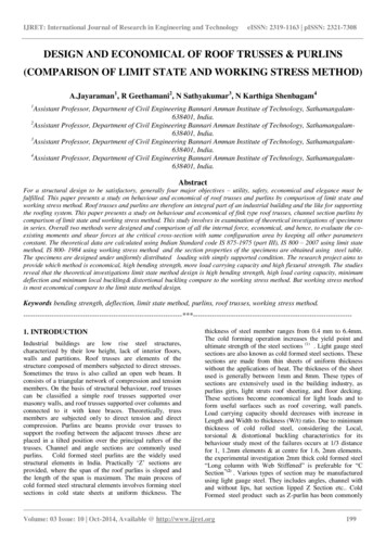
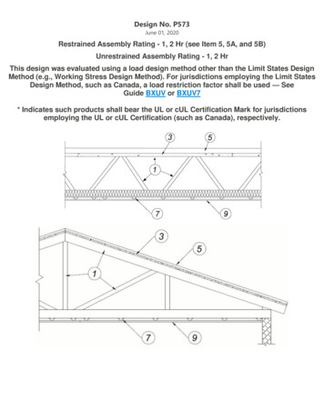
Roof-Floor Truss manual7/31/0810:43 AMPage 17ONE-HOURFIRE RATINGFor Floor TrussesFIRE TESTSDesign No. MCI/FCA 60-02 with Floor Truss Assembly Rating: 60 minutes – Unrestrained Floor/Ceiling Assembly; Finish Rating: 22 minutes1. Topping (Optional): Subject to design and project limitations, thesesystems may be augmented with a lightweight floor topping mixcontaining perlite or vermiculite aggregate.2. Flooring: Minimum 5/8" (15.9mm) plywood or O-2 grade waferboard orstrandboard. See General Information for spacing 16" (400mm) oc.19.2" (500mm) is 3/4" (19.0mm) oc24" (600mm) is 3/4" (19.0mm) oc3. Structural Members: Miitek Canada Inc. Metal Truss Plates with structural graded chords and webs as per NLGA grading rules. All FloorTrusses are to be designed and sealed by a Professional Engineer.4.Furring Channels (Resilient Channel): 7/8" deep with 26 gaugegalvanized steel wired to underside of each truss with double strandsof 18 gauge steel tie wire or screwed to each truss with 1-1/4" Type Sdrywall screws. Double rows of furring channels at each gypsumwallboard joist (at least 3" apart).5. Bridging/Strongback: 2 x 6 SPF #2 to be screwed to the bottom chord with two 3" screws and spaced 7' oc.6.Gypsum Board: 4' x 10' x 5/8" Type C (listed Firecode C or Westroc Fireboard C) with edges runningperpendicular to the furring channels. Screwed to channels with 1-1/4" Type S bugle head drywall screws set at12" oc & 1-1/2" from edges of board (minimum). All joints to be taped. Joints and screw heads covered with 2layers of gyproc joint filler.SEE NEXT PAGEFOR GENERALINFORMATION7. Insulation (optional): It may be 3-1/2" (89mm) thick fiberglass insulation batts with density 0.75 lb/cu. ft.All batts are to be placed between bottom joist flanges and supported by metal furring channels. All buttjoints shall be over furring channels.GA* Design No. FC 5517UL** Design No. L528The Truss Plate Institute has author-3/4" T&G plywood, glued and nailedwith alt. lightweight concrete3/4" T&G plywood, glued and nailed withalt. lightweight concreteized fire tests be conducted toachieve a one-hour fire rating for atypical floor and ceiling assembly.2x4 or 4x2parallel chordtrusses@max. 24" o.c.2x4 or 4x2roof or floortrusses @max.24" o.c.Copies of those reports are availablefrom the issuing agencies.Fire rating test results are summa-4x2 wood blockZ-clipFurring channels1 layer 5/8" thick USG Firecode C,Type C gypsum wallboard fastenedwith 1-7/8" Type S screws @ 8" o.c.1 layer 5/8" thick Type C, USGgypsum wallboard securedwith screws, joints finishedrized in the adjacent illustrations.Additional information regardingone-hour fire ratings using woodtrusses with gypsum board ceilingUL** Design No. L529Factory Mutual*** Design FC2143/4" T&G plywood, glued and nailedwith alt. lightweight concrete3/4" T&G plywood, glued and nailedmay be obtained from ICBOResearch Reports No. 1632 and 1352.2x4 or 4x2parallel chordtrusses@max. 24" o.c.2x4 or 4x2parallel chordtrusses@max. 24" o.c.Steel cross teesand runners1 layer 5/8" thick Type C, USGgypsum wallboard securedwith screws, joints finished2 layers 1/2" thick Type FSW-1, NGCgypsum wallboard, secured withscrews, joints finishedTMTMW W W. M I I . C O M15
Roof-Floor Truss manual7/31/0810:43 AMPage 18Trackless Floor Truss Roller PressMITEKFIRE DESIGN LISTINGGENERAL INFORMATIONRoof/Ceiling, Floor Ceiling,Beam & Column AssembliesMiTek Canada Inc. fire design listingsare based on, and supported by,proprietary test reports which havebeen reviewed and evaluated byIntertek. The test reports furtherdefine proprietary design detailswhich make these listings applicableonly to the specified productsmanufactured by MiTek Canada Inc.continued from page 15Unless otherwise noted, panels are T & G,maximum width 48" with long dimensionsinstalled perpendicular to joists. End joistsare staggered minimum 24" and butted overjoists. Unless otherwise noted, minimumnominal thickness of sub-flooring is:MaximumJoistsSpacing(mm)Plywood & O-2Grade Waferboard& Strandboard(mm)Waferboard &StrandboardR-1 & O-1 Grade(mm)16" (400)19.2" (500)24" (600)5/8" (15.9)3/4" (19.0)3/4" (19.0)5/8" (15.9)3/4" (19.0)3/4" (19.0)The following fire assembly designsare listed in accordance withASTM-E119 (Fire Tests of BuildingConstruction Materials),Sub-Flooring Fastening: Minimum length offastener for sheathing and subfloor attachment for thickness from 5/8" (15.9mm) to3/4" (19.0mm) thick is:CAN/ULC-S101 (Standard Methodsof Fire Endurance Tests of BuildingConstruction and Materials),NFPA-251 (Fires Tests of BuildingConstruction and Materials), UBC-7-1(formerly UBC-43-1), UniformBuilding Code Standard).a) Common or Spiral Nail: 2" (51mm)(Canada); 8d (0.131" dia. x 2.5" long) (U.S.)General InformationApplicable to all MiTek DesignsFloor Topping: Subject to designand project limitations, thesesystems may be augmented witha lightweight floor topping mixcontaining perlite or vermiculiteaggregate.Sub-Flooring: Sub-floor panels toconform to one of the following:MaterialCanadian Std.U.S. Std.Douglas Fir CAN/CSA-0121PlywoodPS-1-83Grp 1 strut.SoftwoodPlywoodCAN/CSA-0151PS-1-83Grp III C-DPoplarPlywoodCAN/CSA-0153PS-1-83C-DWaferboard CAN-0437.0andStrandboardSheathingCAN/CSA-0325.0 PS-2-92Note: All plywood are to be produced withadhesive qualified as interior use/exteriorgrade (exposure 1) or better.16b) Ring Thread Nail: 1-3/4" (45mm)(Canada); 6d (0.120" dia. x 2" long) (U.S.)Nail spacing shall be 6" (150mm) o.c. alongbutt edges of panel and 12" (300mm)(Canada) and 10" (U.S.) o.c. along intermediate support.Structural Members: Listed fire designs arebased on systems designed for structuraland functional performance in accordancewith MiTek Canada Inc. procedures. Alldesigns are tested in unrestrained configuration. The chord materials are structural ratedlumber material as graded under NLGA-1993Standard Grading rules for Canadian Lumberor graded by an inspection bureau or agencyapproved by the U.S. Department ofCommerce Board of Review of the AmericanLumber Standards Committee with chordsizes of 3x2, 4x2, 5x2.MiTek Posi-Strut Series: Unless otherwisespecified, this includes PS-10, PS-10V2, PS-12,PS12V2, PS-12i, PS-13, PS-14, PS-14V3, PS-16,PS-16V3 metal webs having a minimumdepth of 9-1/4" and spaced up to a maximumof 24" o.c. for floor/ceiling systems. MiTekFloor Truss Series: Unless otherwise specified, this includes wood web floor trussdesigns with metal truss plates manufacturedby MiTek Canada Inc. having a minimumdepth of 10" and spaced up to a maximum of24" o.c. for floor/ceiling systems.Resilient Channel: Can be used in all cases,directly applied to joists. Minimum requirement is 26 gauge galvanized steel. Unlessotherwise noted, maximum spacing is 24"o.c., perpendicular to joists and fastened toeach joist with one 1-1/4" Type S drywallscrew. Double rows of furring channels ateach gypsum wall board joint (at least 3"apart).Gypsum Board: All Gypsum Board is listed5/8" (15.9mm) Type X, unless otherwisenoted. In certain cases, as noted, it may bespecific proprietary type with other designations identified in conjunction with the manufacturer’s name. Maximum width is 48" andunless otherwise noted, all exposed joints aretaped and finished with two additional coatsof joint compound. Screw heads are coveredwith two coats of joint compound.Bridging/Strongback: 2x6Bridging/Strongback to be attached to eachbottom chord of the assembly with two 3"screws and to be spaced 7" o.c.Insulation: Where design requires insulation,it shall be 1-1/2" (38mm) thick mineral woolinsulation batts. Where insulation is optional,it may be 3-1/2" (89mm) thick fiberglassinsulation batts with density 0.75 lb/cu. ft. Allbatts are to be placed between bottom joistflanges and supported by metal furring channels. All butt joints shall be over furring channels.Suspended Ceiling System: Any suspendedceiling system may be selected whichsatisfies the following criteria:a) It must be a fire-rated system, and beinstalled within the terms of its listing.b) It must have a finish rating equal to orgreater that the finish rating required bythe suspended ceiling design.c) It must be suspended in accordance withthe terms of its listing and a minimum of7-1/2" below the joist.d) Penetrations such as ducts, air diffusers,and fixtures must be protected in such amanner as to conform to the terms of thelisting of the suspended ceiling system.
Roof-Floor Truss manual7/31/0810:43 AMPage 19SOUND TRANSMISSIONRATINGSTechnical Information - Floor/Ceiling SystemsCALCULATION EXAMPLEVarious floor-ceiling systems exhibit different abilities to reduce sound transfer from oneroom to another. This sound transmission resistance is measured by two indices - the SoundDescriptionSTCIICCarpet and Padding020Transmission Class (STC) which rates airborne sounds to evaluate the comfortability of aparticular living space and the Impact Insulation Class (IIC) which rates the impact soundtransmission performance of an assembly. These ratings are used by regional buildingcodes to regulate permissible sound transfer.71Wood Truss Floor3633Resilient Channel108Total53623/4” GypcreteFor more detailed information reference the Metal Plate Connected Wood Truss Handbook, 1993 Wood Truss Council of America, Section 18.0 - Transitory Floor Vibration and SoundTransmission.STC HighFrequencyIIC LowFrequencyBasic Wood Floor - consisting of wood joist(I-joist, solid-sawn or truss), 3/4” decking and 5/8”gypsum wallboard attached directly to ceiling3633Cushioned Vinyl or Linoleum02Non-cushioned Vinyl or Linoleum001/2” Parquet Flooring013/4” Gypcrete or Elastizel 7-811-1/2” Lightweight Concrete7-8115Description1/2” Sound Deadening Board (USG)*Quiet-Cor Underlayment by Tarkett, Inc*18Enkasonic by American Enka Company*413Sempafloor by Laminating Services, Inc.*111R-19 Batt Insulation20R-11 Batt Insulation10103" Mineral Wood InsulationResilient Channel108Resilient with Insulation1315Extra Layer of 5/8" Gypsum WallboardCarpet and Padding0-22-4020-25* Estimates base on proprietary literature. Verify with individual companies. The information in thechart above was excerpted from the Construction Guide for Southern Pine Joist & Rafters.Southern Pine Council, 1993.TMW W W. M I I . C O M17
Roof-Floor Truss manual7/31/0810:43 AMPage 20TECHNICALINFORMATIONAPPLIED LOADSREPRESENTATIVEFLOOR & ROOF LOADING40 psf TC live loadTYPICAL CONSTRUCTIONMATERIAL WEIGHTS10 psf TC dead load(3/4" plywood decking)Floors0 psf BC live loadHardwood (1 in. thick) . . . . . . . . . . . . . . .3.8235 lb. shingles and paper . . . . . . . . . . .2.5Concrete2-15 lb. and 1-90 lb. . . . . . . . . . . . . . . . . . .1.7Residential Flooring5 psf BC dead load(1/2" to 5/8" drywall)55 psf total load(If heavy insulation or 2-plydrywall ceiling, BC dead load 10 psf and 40/10/0/10 60 psftotal load)Composition RoofingpsfRegular (1 in. thick) . . . . . . . . . . . . . . .12.03-15 lb. and 1-90 lb. . . . . . . . . . . . . . . . . . . .2.2Lightweight (1 in. thick) . . . . . . . . . . . .8.03-ply and gravel . . . . . . . . . . . . . . . . . . . . . .5.6Linoleum . . . . . . . . . . . . . . . . . . . . . . . . . . .1.54-ply and gravel . . . . . . . . . . . . . . . . . . . . . .6.03/4" ceramic or quarry tile . . . . . . . . . . 10.0Roof and Floor SheathingpsfCeiling
engineering software for roof and floor trusses, as well as wall panel design. These programs provide our fabricators with fast and accurate layout and design . our tradition of customer support. Roof-Floor Truss manual 7/31/08 10:42 AM Page 2. CONNECTOR PLATES BRACING & RESTRAINING PRODUCTS TRUSS MANUFACTURING EQUIPMENT DESIGN SOFTWARE .