![Materials For Engineering [by John Martin]](/img/14/materials-20for-20engineering-20-5bby-20john-20martin-5d.jpg)
Transcription
234 x 156 / 307 C & 3025 C14mmThis third edition of what has become a modern classic presents a lively overviewof materials science for students of structural and mechanical engineering. Itcontains chapters on the structure of engineering materials, the determinationof mechanical properties, and the structure–property relationships of metals andalloys, glasses and ceramics, organic polymeric materials and composite materials.It contains a section with 50 thought-provoking questions to check students’knowledge and understanding, as well as a series of useful appendices. The thirdedition includes new topics such as superplasticity and the Bauschinger Effect,expanded coverage of such areas as organic polymers and updated reading lists.Clear, concise and authoritative, the third edition of Materials for engineeringwill confirm its position as an ideal text for undergraduates and a useful referencesource on materials structure and properties for the practising engineer.CRC Press LLC6000 Broken Sound Parkway, NWSuite 300Boca RatonFL 33487USACRC order number WP8780ISBN-10: 0-8493-8780-9Woodhead Publishing LtdAbington HallAbingtonCambridge CB1 6AHEnglandwww.woodheadpublishing.comISBN-13: 978-1-84569-157-8ISBN-10: 1-84569-157-1Im3The Institute of Materials, Minerals & MiningMartinWoodhead Publishing and Maney Publishingon behalf ofThe Institute of Materials, Minerals & MiningThird editionJohn Martin is Emeritus Reader in Physical Metallurgy at the University of Oxfordand recipient of the Platinum Medal of the UK Institute of Materials, Minerals andMining.Materials for engineering‘Outstanding academic title for 2003 – this title has been selected for itsexcellence in scholarship and presentation, the significance of its contribution tothe field, and because of its important treatment of its subject.’ Choice magazineMaterials forengineeringThird editionJohn Martin
Materials for engineering
Related titles:Solving tribology problems in rotating machines(ISBN-13: 978-1-84569-110-3; ISBN-10: 1-84569-110-5)Bearings are widely used in rotating machines. Understanding the factors affecting theirreliability and service life is essential in ensuring good machine design and performance.Solving tribology problems in rotating machines reviews these factors and their implicationsfor improved machine performance.Nanostructure control of materials(ISBN-13: 978-1-85573-933-8; ISBN-10: 1-85573-933-X)Nanotechnology is an area of science and technology where dimensions and tolerances inthe range of 0.1 nm to 100 nm play a critical role. Nanotechnology has opened up newworlds of opportunity. It encompasses precision engineering as well as electronics,electromechanical systems and mainstream biomedical applications in areas as diverse asgene therapy, drug delivery and novel drug discovery techniques. This new book providesdetailed insights into the synthesis/structure and property relationships of nanostructuredmaterials. A valuable book for materials scientists, mechanical and electronic engineers andmedical researchers.Engineering catastrophes, 3rd edn(ISBN-13: 978-1-85573-505-7; ISBN-10: 1-85573-505-9)This new edition of a well received and popular book contains a general update of historicaldata, more material concerning road and rail accidents and, most importantly, a new chapteron the human factor. The author provides a broad survey of the accidents to which engineeringstructures and vehicles may be subject. Historical records are analysed to determine howloss and fatality rates vary with time and these results are displayed in numerous graphs andtables. Notable catastrophes such as the sinking of the Titanic and the Estonia ferry disasterare described. Natural diasters are considered generally, with more detail in this edition onearthquake resistant buildings.Details of these and other Woodhead Publishing materials books and journals, as well asmaterials books from Maney Publishing, can be obtained by: visiting www.woodheadpublishing.com contacting Customer Services (e-mail: sales@woodhead-publishing.com;fax: 44 (0) 1223 893694; tel.: 44 (0) 1223 891358 ext. 30; address:Woodhead Publishing Ltd, Abington Hall, Abington, Cambridge CB1 6AH, England)If you would like to receive information on forthcoming titles, please send your addressdetails to: Francis Dodds (address, tel. and fax as above; email: francisd@woodheadpublishing.com). Please confirm which subject areas you are interested in.Maney currently publishes 16 peer-reviewed materials science and engineering journals.For further information visit www.maney.co.uk/journals.
Materials forengineeringThird editionJ. W. MartinWoodhead Publishing and Maney Publishingon behalf ofThe Institute of Materials, Minerals & MiningCRC PressBoca Raton Boston New York Washington, DCWOODHEADPUBLISHING LIMITEDCambridge England
Woodhead Publishing Limited and Maney Publishing Limited on behalf ofThe Institute of Materials, Minerals & MiningWoodhead Publishing Limited, Abington Hall, Abington,Cambridge CB1 6AH, Englandwww.woodheadpublishing.comPublished in North America by CRC Press LLC, 6000 Broken Sound Parkway, NW,Suite 300, Boca Raton, FL 33487, USAFirst published 1996.Second edition published 2002 by Maney Publishing for The Institute of MaterialsThird edition published 2006, Woodhead Publishing Limited and CRC Press LLC Woodhead Publishing Limited, 2006The author has asserted his moral rights.This book contains information obtained from authentic and highly regarded sources.Reprinted material is quoted with permission, and sources are indicated. Reasonableefforts have been made to publish reliable data and information, but the author andthe publishers cannot assume responsibility for the validity of all materials. Neitherthe author nor the publishers, nor anyone else associated with this publication, shallbe liable for any loss, damage or liability directly or indirectly caused or alleged to becaused by this book.Neither this book nor any part may be reproduced or transmitted in any form or byany means, electronic or mechanical, including photocopying, microfilming andrecording, or by any information storage or retrieval system, without permission inwriting from Woodhead Publishing Limited.The consent of Woodhead Publishing Limited does not extend to copying forgeneral distribution, for promotion, for creating new works, or for resale. Specificpermission must be obtained in writing from Woodhead Publishing Limited for suchcopying.Trademark notice: Product or corporate names may be trademarks or registeredtrademarks, and are used only for identification and explanation, without intent toinfringe.British Library Cataloguing in Publication DataA catalogue record for this book is available from the British Library.Library of Congress Cataloging in Publication DataA catalog record for this book is available from the Library of Congress.Woodhead Publishing Limited ISBN-13:Woodhead Publishing Limited ISBN-10:Woodhead Publishing Limited ISBN-13:Woodhead Publishing Limited ISBN-10:CRC Press ISBN-10: 0-8493-8780-9CRC Press order number: WP8780978-1-84569-157-8 (book)1-84569-157-1 (book)978-1-84569-160-8 (e-book)1-84569-160-1 (e-book)The publishers’ policy is to use permanent paper from mills that operate asustainable forestry policy, and which has been manufactured from pulpwhich is processed using acid-free and elementary chlorine-free practices.Furthermore, the publishers ensure that the text paper and cover board usedhave met acceptable environmental accreditation standards.Typeset by Replika Press Pvt Ltd, IndiaPrinted by TJ International, Padstow, Cornwall, England
ContentsPreface to the third editionixPreface to the second editionxiPreface to the first editionIntroductionxiiixvPart I Characterization of engineering materials1 Structure of engineering materials31.11.21.31.4Crystal structureMicrostructureMolecular structure of organic polymers and glassesFurther reading3727352Determination of mechanical properties372.12.22.32.42.52.62.7IntroductionThe tensile testBend testingStatistics of brittle fractureHardness testingFracture toughness testingTime-dependent mechanical properties37374345454752Part II Structure–property relationships3Metals and alloys3.13.23.3General strengthening mechanisms: the effect of processingThe families of engineering alloysJoining of metals and alloys717184115
viContents3.43.5Degradation of metals and alloysFurther reading1221314Glasses and ceramics1334.14.24.34.44.54.6GlassesGlass ceramicsCeramic materialsCement and concreteBulk metallic glassesFurther reading1331381391471561585Organic polymeric rming processes for polymersDirectionality of propertiesMechanical propertiesJoining of polymersPolymer degradationModelling of polymer structure and propertiesFurther reading1591611631631751791821846Composite materials1856.16.26.36.46.5IntroductionManufacture of composite materialsCellular solidsModelling composite behaviourFurther reading185186191194214Part III lems219221224226226227
ContentsviiPart IV AppendicesIIIIIIIVVIndexUseful constantsConversion factorsSelected data for some elementsSources of material property dataThe Periodic Table of the elements231233235237241243
Preface to the third editionThe criterion I have adopted for discussing a specific material in this bookis its commercial availability, rather than its being confined to a research anddevelopment laboratory. In the ten years since the appearance of the firstedition of the book, a number of such engineering materials have appearedon the market and a number of these will be discussed in the pages below.I have also taken the opportunity of including a few topics of engineeringimportance that were originally omitted. Typical examples are the phenomenaof superplasticity and the Bauschinger Effect. The chapter on organic polymericmaterials now includes a fuller introduction to the range of those commerciallyavailable, and their typical applications.The suggested reading lists at the end of chapters have been updatedwhere necessary, as has the Appendix devoted to a review of the sources ofmaterial property data (though the latter is essentially a moving target and socan never be fully comprehensive!).I continue to appreciate with gratitude the support and encouragement ofmy colleagues notably that of Professor George Smith, FRS, for allowing meaccess to the facilities of the Department of Materials at the University ofOxford.John W. Martin
Preface to the second editionSince the appearance of the first edition of the book, it has been pointed outto me that its value to the student reader would be increased if a series ofrelated problems were included. Over 50 such problems have been devised,and they appear at the end of the text.The opportunity has also been taken to correct a number of misprints anderrors which appeared in the earlier edition. I am particularly indebted toProfessor Christopher Viney of Heriot-Watt University for his assistance inthis regard.
Preface to the first editionThis textbook represents an attempt to present a relatively brief overview ofMaterials Science, the anticipated readership being students of structural andmechanical engineering. It is in two sections – the first characterisingengineering materials, the second considering structure–property relationships.Emphasis is thus placed on the relationship between structure and propertiesof materials, starting with the concept of ‘structure’ at three levels – crystalstructure, microstructure, and molecular structure. The discussion ofmicrostructure introduces the topics of phase transformations, metallographyand phase diagrams – none of which would be familiar to the intended readership.After a section on the determination of mechanical properties, the remainingfour chapters deal with the four important classes of engineering materials,namely metals, ceramics, polymers and composites. It is estimated that thereare some 40 000 metallic alloys in existence, over 5000 polymers and some2000 ceramic materials, so there is some justification in discussing metalsand alloys at the greatest length. In that chapter, an attempt has been madeto consider initially the general principles of strengthening, so that the individualfamilies of engineering alloys can be discussed in the light of this introduction.About equal emphasis is placed on the remaining classes of materials.The tables of data within the text, and the Appendices, have been selectedto increase the value of the book as a permanent source of reference to thereaders throughout their professional life. The latter include:Useful constantsUnit conversion factorsSelected data for some elementsA list of sources of material property data, in the form of both handbooksand database software.The Periodic Table of the elementsThe author is pleased to acknowledge the encouragement and suggestionsgiven by the members of the University Books Sub-Committee of the Instituteof Materials, Minerals & Mining. I am also most grateful to Professors B.Cantor and D. G. Pettifor, FRS, for the facilities they have kindly providedfor me in the Oxford University Department of Materials and to PeterDanckwerts for his efficient dealing with editorial matters.
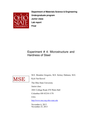
IntroductionThe materials available to engineers for structural applications embrace anextremely wide range of properties. We can classify them into THREE broadfamilies as follows:METALS & ALLOYSENGINEERING CERAMICS & GLASSESENGINEERING POLYMERS & ELASTOMERSThere is the further possibility that materials from two or more of thesefamilies may themselves be combined to form a FOURTH family, namely:COMPOSITE MATERIALSIt is possible to present a broad ‘overview’ of the properties of engineeringmaterials by constructing a Material Property Chart. These charts show therelationship between two selected engineering properties of the above families,and Fig. 0.1 (due to Ashby) illustrates the Young’s modulus–density chart forengineering materials.Young’s elastic modulus is one of the most self-evident of material properties,reflecting as it does the stiffness of structural steel or the compliance ofrubber. Because of this wide range of values, the scales of the axes inFig. 0.1 are logarithmic, and their ranges have been chosen to include allmaterials from light polymeric foams to engineering alloys.Data for a given family of materials are seen to cluster together on thechart, and each family has been enclosed within an envelope in the diagram.Although each class of material has characteristic properties, these may varywithin each class because of variations in structure at three different levels,
xviIntroductionYoung’s modulus, E (GPa)1000EngineeringWC-CeDiamondceramicsB SiCSi3H4SteelsAluminasMo W-alloysSialons ZrO2CFRPBeOSiNi-alloysCeuni-plyCu-alloysGlasses Pottery100KFRPEngineeringTi-alloys Zn-alloys1/2Al-alloysGFRPTincomposites E Rock, stoneCFRPalloys Lead ρ (m / s)Cement,concrete LaminatesalloysGFRP KFRP4Parallel10AshMgto grain Oakalloys Porous Engineering10MELFir PineceramicsalloysPPSBalsadEpoxiesoo ctsW duPMMAoprPVCWoodsPPNylon3 103Lower limitAsh1Polyestersfor true solidsOakHDPEPerpendicular PineGuide lines forFirPTFEto grainminimumLDPESpruceEweight design CBalsaPlasticised ρPVC1030.11. Modulus–DensityYoung’s modulus E(G 3E/8 : K E)MFA: 88-913 102Cork0.010.1Polymersfoams0.3HardPU Elastomersbutyl1/2Eρ CSoft SiliconebutylE 1/3 Cρ1.03.0Density, ρ (Mg/m3)10300.1 Young’s modulus, E, vs. density, ρ. (After M. F. Ashby, ActaMetall., 1989, 37, 1273).namely the atomic arrangement, or crystal structure, the microstructure,which refers to the size and arrangement of the crystals, and the molecularstructure. We will consider these aspects of structure in turn.
Part ICharacterization of engineering materials
1Structure of engineering materials1.1Crystal structureCrystal structure refers to the ordering of atoms into different crystallinearrangements. It is the arrangement of these atoms – the strength anddirectionality of the interatomic bonds – which determines the ultimate strengthof the solid. Techniques involving X-ray or electron diffraction are employedto determine crystal structures, and four types of interatomic bonding arerecognized: van der Waals, covalent, ionic and metallic. The latter three‘primary’ bonds are limiting cases, however, and a whole range of intermediatebonding situations also exist in solids.The van der Waals force is a weak ‘secondary’ bond and it arises as aresult of fluctuating charges in an atom. There will be additional forces ifatoms or molecules have permanent dipoles as a result of the arrangement ofcharge inside them. In spite of their low strength, these forces can still beimportant in some solids; for example it is an important factor in determiningthe structure of many polymeric solids.Many common polymers consist of long molecular carbon chains withstrong bonds joining the atoms in the chain, but with the relatively weak vander Waals bonds joining the chains to each other. Polymers with this structureare thermoplastic, i.e. they soften with increasing temperatures and are readilydeformed, but on cooling they assume their original low-temperature propertiesand retain the shape into which they were formed.Covalent bonding is most simply exemplified by the molecules of thenon-metallic elements hydrogen, carbon, nitrogen, oxygen and fluorine. Theessential feature of a covalent bond is the sharing of electrons betweenatoms, enabling them to attain the stable configuration corresponding to afilled outermost electron shell. Thus, an atom with n electrons in that shellcan bond with only 8 – n neighbours by sharing electrons with them.For example, when n 4, as in carbon in the form of diamond, one of thehardest materials known, each atom is bonded equally to four neighbours atthe corners of a regular tetrahedron and the crystal consists of a covalent3
4Materials for engineeringmolecule, Fig.1.1(a). In graphite, only three of the four electrons form covalentbonds, so a layer structure forms, Fig. 1.1(b), and the fourth electron is free,which gives some metallic properties to this form of carbon. Graphite crystalsare flat and plate-like, and they are so soft that graphite is used as a lubricant.It is clear from Fig. 1.1 that the different dispositions of the covalent bondsin space have a profound influence on the atomic arrangements and henceupon properties of the material.For many years diamond and graphite were the only known forms ofcarbon, but, in 1985, a new form of carbon (buckminsterfullerene), C60, wasidentified, Fig. 1.1(c), as a soccer-ball-like cage of 60 carbon atoms with adiameter of 0.71 nm. This was the only allotrope of any element to have beendiscovered in the twentieth century. Other, larger, fullerene ‘buckeyballs’have subsequently been discovered and, in 1991, multiwalled carbon nanotubeswere discovered. Two years later, single-walled carbon nanotubes werediscovered with diameters generally varying between 1.3 and 1.6 nm. Figure1.1(d) is an electron micrograph showing a series of fullerene buckeyballswithin a carbon nanotube. Carbon nanotubes can be synthesized by a numberof techniques, including carbon arcs, laser vaporization and ion bombardment.(a)(b)(c)5 nm(d)1.1 Crystal structure of (a) diamond; (b) graphite; (c) buckminsterfullerene,C60; and (d) electron micrograph of a series of buckeyballs within acarbon nanotube: a diagram of the structure is shown underneath.(Courtesy Dr Andrei Khlobystov.)
Structure of engineering materials5They consist of concentric, cylindrical, graphitic carbon layers capped onthe ends with fullerene-like domes.The possibility of encapsulating atoms (and molecules) inside the fullerenecages is of considerable interest, giving rise to materials with highly modifiedelectronic properties and thus opening the way to novel materials with uniquechemical and physical properties. The Young’s modulus of multiwallednanotubes has been measured to be 1.26 TPa and this high strength may beexploited by incorporating them in composite materials.The elements can be divided into two classes, electronegative elements(such as oxygen, sulphur and the halogens) that tend to gain a few electronsto form negatively charged ions with stable electron shells, and electropositiveelements (such as metals) that easily dissociate into positive ions and freeelectrons. Ionic bonding consists of an electrostatic attraction between positiveand negative ions. If free atoms of an electropositive element and anelectronegative element are brought together, positive and negative ions willbe formed which will be pulled together by electrostatic interaction until theelectron clouds of the two ions start to overlap, which gives rise to a repulsiveforce. The ions thus adopt an equilibrium spacing at a distance apart wherethe attractive and repulsive forces just balance each other.Figure 1.2 shows a diagram of the structure of a sodium chloride crystal:here each Na ion is surrounded by six Cl– ions and each Cl– is surroundedby six Na ions. Many of the physical properties of ionic crystals may beaccounted for qualitatively in terms of the characteristics of the ionic bond;for example they possess low electrical conductivity at low temperatures,but good ionic conductivity at high temperatures. The important ceramicNaCl1.2 Crystal structure of sodium chloride.
6Materials for engineeringmaterials consisting of compounds of metals with oxygen ions are largelyionically bonded (MgO, Al2O3, ZrO2, etc).Metallic bonding. About two-thirds of all elements are metals, and thedistinguishing feature of metal atoms is the looseness with which their valenceelectrons are held. Metallic bonding is non-directional and the electrons aremore or less free to travel through the solid. The attractions between thepositive ions and the electron ‘gas’ give the structure its coherence, Fig. 1.3.The limit to the number of atoms that can touch a particular atom is set bythe amount of room available and not by how many bonds are formed.‘Close-packed’ structures, in which each atom is touched by twelve others,are common and they give rise to the typical high density of metals. Sinceeach atom has a large number of neighbours, the overall cohesion is strongand metals are therefore similar to ionic and covalent solids as regardsstrength and melting point.In general, the fewer the number of valence electrons an atom has and themore loosely the electrons are held, the more metallic the bonding. Suchelements have high electrical and thermal conductivities because their valenceelectrons are so mobile. Although a satisfactory description of some of thephysical properties of metals can be obtained from this ‘free electron’ picture,many other properties (particularly those concerned with the motion of electronswithin metal crystals) have to be explained in terms of electrons as wavesoccupying definite quantized energy states.As the number of valence electrons and the tightness with which they areheld to the nucleus increase, they become more localized in space, increasingthe covalent nature of the bonding. Group IVB of the Periodic Table illustratesparticularly well this competition between covalent and metallic bonding:diamond exhibits almost pure covalent bonding, silicon and germanium aremore metallic, tin exists in two modifications, one mostly covalent and theother mostly metallic, and lead is mostly metallic.Nucleus plusinner electronsElectron cloud1.3 Classical model of a metal crystal.
Structure of engineering materials1.27MicrostructureMicrostructure refers to the size and arrangement of the crystals, and theamount and distribution of impurities in the material. The scale of thesefeatures is typically 1–100 µm. Microstructure determines many of theproperties of metals and ceramics.1.2.1Introduction to phase transformationsThe transition from the liquid state to the solid state is known as ‘crystallization’,and the mechanism by which the process takes place controls the microstructureof the final product. A phase transformation, such as the change from liquidto solid, occurs by the mechanism of nucleation of small ‘seed’ crystals inthe liquid, which then grow by the addition of more material from the liquid.The driving force for this change can be obtained by considering the changein free energy on solidification. For example, if a liquid is undercooled by T below its melting point (Tm) before it solidifies, solidification will beaccompanied by a decrease in the Gibbs free energy of G. The Gibbs freeenergy of a system is defined by the equationG H – TSwhere H is the enthalpy, T the absolute temperature and S the entropy of thesystem. The free energies of the liquid and solid at temperature T are givenbyGL HL – TSLGS HS – TSSso that at temperature T, the change in free energy/unit volume uponsolidification may be written: Gv H – T S[1.1]where H HL – HS and S SL – SSAt the equilibrium melting temperature Tm, Gv 0, thus S H/Tm L/Tm[1.2.]where L is the latent heat of fusion. Combining equations [1.1] and [1.2]gives Gv L – T(L/Tm)Thus, for an undercooling T, Gv L T/Tm[1.3]
8Materials for engineeringEquation [1.3] shows that the higher the degree of supercooling, the greaterthe free energy decrease, and this is a most useful result to which we willreturn.NucleationConsider a given volume of liquid supercooled below Tm by a temperatureinterval T. If a small sphere of solid forms (radius r), the free energy of thesystem will be lowered by an amount per unit volume corresponding toequation [1.3]. Energy is required, however, to create the solid/liquid interface,of energy γSL per unit area. The free energy change in the system may bewritten: G –(4/3)πr3 Gv 4πr 2 γSL[1.4]Figure1.4 illustrates this relationship and it may be seen that, for a givenundercooling, there is a certain critical radius, rc, of the solid particle. Solidparticles with r rc, known as embryos, will redissolve in the liquid to lowerthe free energy of the system, whereas particles with r rc, known as nuclei,will grow in order to decrease the energy of the system.By differentiation of equation [1.4] it can be shown that:rc 2γSL/ Gv[1.5] GInterfacialenergy r2 G*0rrc GVolume freeenergy r3 T1.4 Free energy change associated with the nucleation of a sphere ofradius r.
Structure of engineering materials9and substituting equation [1.3] gives:rc (2γSLTm /L)(1/ T)[1.6]indicating that rc decreases with increasing undercooling.For small degrees of undercooling, therefore, rc is large and there is onlya low probability that a large embryo will be formed in the liquid in a giventime by random thermal motion of the atoms. There is thus likely to be onlya low number of successful nuclei per unit volume of liquid. For high degreesof undercooling, rc is small and the probability of forming such a nucleus isnow very high, so that a high number of successful nuclei per unit volume ofliquid will be observed. The implication of these effects upon the resultantmicrostructure will be considered next.Growth of nuclei. Once stable nuclei are formed in the liquid, they growat the expense of the surrounding liquid until the whole volume is solid.Most crystal nuclei are observed to grow more rapidly along certaincrystallographic directions, causing spike-shaped crystals to develop. Furtherarms may branch out sideways from the primary spikes, resulting in crystalswith a three-dimensional array of branches known as dendrites, as shown inFig. 1.5(a).Dendrites grow outwards from each crystal nucleus until they meet otherdendrites from nearby nuclei. Growth then halts and the remaining liquidfreezes in the gaps between the dendrite arms, as shown in Fig. 1.5(b). Eachoriginal nucleus thus produces a grain of its own, separated from theneighbouring grains by a grain boundary, which is a narrow transition regionin which the atoms adjust themselves from the arrangement within one grainto that in the other orientation.12341.5 (a) Drawing of a dendrite and (b) schematic view of the freezingof a liquid by nucleation and growth of dendrites.
10Materials for engineeringThe grain size of a solidified liquid will thus depend on the number ofnuclei formed, and thus on the degree of undercooling of the liquid. Forexample, if a liquid metal is poured into a (cold) mould, the layer of liquidnext to the wall of the mould is cooled very rapidly. This gives rise to a verylarge local undercooling with the result that very many small nuclei of thesolid are formed upon the mould wall and these grow to produce a very finegrained layer of crystals (each perhaps less than 100 µm in size) at thesurface of the casting, known as the ‘chilled layer’.The converse situation arises in nature over geological periods of time,when molten rock may cool very slowly and nucleation takes place at smallundercoolings. Few nuclei form, since rc is so large, and beautiful mineralcrystals of centimetre dimensions are commonly found. The grain size of amaterial is thus an important microstructural feature and we will discusslater how its value may be controlled and what effect its magnitude mayhave upon the mechanical properties of the material.1.2.2Introduction to metallographyLet us next consider the various techniques for microstructural examination.It is usually necessary to prepare a section of a material in order to study thesize, shape and distribution of crystals within it. In the case of metallicmaterials, this is referred to as metallographic examination (‘materialography’is sometimes used more generally), and great precautions have to be taken atevery stage to ensure that the method of preparation does not itself alter themicrostructure originally present.If the section for study is c
Materials for engineering John Martin ‘Outstanding academic title for 2003 – this title has been selected for its . Clear, concise and authoritative, the third edition of Materials for engineering . 5.2 Forming processes