Transcription
OARDBITUMINUOSBUILDINGBLOCKBLOCKINGBEAMBOTTOM OFBASEMENTBETWEENBUILT-UP ROOFBUILT-UP CTSKCYLCABINETCATCH BASINCENTER TO CENTERCEMENTCERAMICCORNER GUARDCAST IRONCAST IN PLACECONTROL JOINTCEILINGCAULKINGCLOSETCLEARCOUNTERCLEAN OUTCOLUMNCOMBUSTIONCOMPOSITIONCONCRETE MASONRY ORCARPETCASEMENT (WINDOW)CERAMIC OUBLEDEPARTMENTDRINKING FOUNTAINDOUGLAS FIR PRESSURE TREATEDDOUBLE HUNG (WINDOW)DIAMETERDIFFUSERDIMENSIONDIMENSION POINTDISPOSALDOWNDOOR OPENINGDOORDOWNSPOUTDRY \Projects\ACSO Training Tower\2021007.Alameda County Fire Training Tower.rvtCopyright 2015 AE3 PARTNERS All Rights Reserved - These Plans and/or Specifications are intended for the sole benefit of AE3 Partners client and may not be copied, reproduced, used or reused in any form without the express written consent of AE3Partners.8/6/2021 11:19:42 ANICNONOMNRNTSQTQTYQUALQUARRY EQRETREVREVERRFRHRMRNDROROWRWDRWLRELOCATEDRISER OR RADIUSRADIUSROOF DRAINREINFORCING BARREFERENCEREFLECTED OR EVISION OR REVISEDREVERSEDRESILIENT FLOORINGRIGHT HANDROOMROUNDROUGH OPENINGRIGHT OF WAYREDWOODRAIN WATER LEADER5301 MADIGAN ROADDUBLIN, CA 94568TREADTOP AND BOTTOMTONGUE AND GROOVETOWEL BARTRASH COMPACTORTOWEL RESHOLDTOP OFTOP OF WALLTOILET PAPER HOLDERTRASH RECEPTACLETUBE STEELTYPICALTESSUNDERWRITERS LABORATORIES, INC.UNFINISHEDUNLESS OTHERWISE NOTEDWITHWASHER AND DRYERWEST OR WIDEWITHOUTWATER CLOSETWOODWATER HEATERWHERE OCCURSWATERPROOFWATERPROOFING MEMBRANEWATER RESISTANTWEATHERSTRIPPINGWAINSCOTWET STANDPIPEWEIGHTSEVICINITY MAPRGORVINYL COMPOSITE TILEVERTICALVESTIBULEVERIFY IN FIELDGeneral Services AgencyCapital Programs1401 Lakeside DriveOakland CA, 94612YYYY-MM-DDISSUE/REVISIONNO.PROJECT DIRECTORYCLIENTDSA1401 LAKESIDE DRIVEOAKLAND CA, 94612CONTACT: DAVID BARBAE:DAVID.BARBA@ACGOV.ORGSITEARCHITECTUREAE3 PARTNERS315 MONTGOMERY ST., SUITE 1000SAN FRANCISCO, CA 94111CONTACT: DOUGLAS DAVIST: 415.651.4592E: DOUGD@AE3PARTNERS.COMPSTRUCTURALKPFF45 FREMONT ST., 28th FLOORSAN FRANCISCO, CA 94105CONTACT: BRIAN BIEHLE: BRIAN.BIEHL@KPFF.COMKEY PLANNNELECTRICALRANDALL LAMB ASSOCIATES, INC500 WASHINGTON ST, SUITE 200SAN FRANCISCO, CA 94111CONTACT: AARON STRAUCHE: ASTRAUCH@RANDALLLAMB.COMPROFESSIONAL SEALSBUILDING INFORMATIONLOCATION:5301 MADIGAN ROADDUBLIN, CA 94568CONSTRUCTION TYPE:IIBNUMBER OF STORIES:FOUROCCUPANCY:ASCOPE OF WORKERECTING A TACTICAL TRAINING SYSTEM 4000 SERIES PERMANUFACTURER’S SHOP DRAWINGSINTERIOR CONSTRUCTION: NON COMBUSTIBLE:DEFERRED SUBMITTALAPPLICABLE CODESALL WORK SHALL FULLY COMPLY BUT NOT BE LIMITED TO:NOITCRUTSS ED A RC HE N LA S A . D I TAGVIFIXED POSITION (WINDOW)FIRE ALARMFORCED AIR UNITFLOOR DRAINFOUNDATIONFIRE EXTINGUISHERFIRE EXTINGUISHER CABINETFINISH FLOORFIRE HOSE CABINETFLAT HEAD MACHINE SCREWFINISHFIXTUREFLOORFLASHINGFLUORESCENTFACE OFFACE OF FINISHFACE OF STUDFACE OF TREADFIREPLACEFIREPROOFFIRE RESISTIVEFRAMINGFIBERGLASS REINFORCEDPOLYESTER PANELFULL SIZEFLOOR SINKFEET OR FOOTFOOTINGFURRINGOKITKHB275 Battery Street, Suite 1050San Francisco, California s.comTEC FOSFOTFPLFPRFFRFRMGFRPPIECE OR PRECASTPERPENDICULARPOCKET (DOOR)PLATEPLASTIC ER OWNER'S R TOWEL DISPENSERPAINTEDPARTITIONPAPER TOWEL RECEPTACLEPOLY VINYL CHLORIDEJANJCTJSTJTACSOTRAINING TOWERSITE ELEVATIONSCOVERSITE PLANGREEN BUILDING CHECKLISTGREEN BUILDING CHECKLISTTITLE PAGEGENERAL NOTESFOUNDATION PLANFOUNDATION DETAILSNNO.C-28047OCEXP. 08-31-21ROFTONTEAEXISTINGEASTEACHEXTERIOR FACE OF STUDEXPANSION EDGE OFELECTRICAL PANELEQUALEQUIPMENTELECTRICAL WATER DPTNPTRECPVCIDINCANINSULINTSOLID CORE WOOD DOORSOAP DISH OR DISPENSERSECTIONSEE ELECTRICAL DRAWINGSSQUARE FEETSEE FIRE PROTECTION DRAWINGSSLIDING GLASS DOORSINGLE HUNG (WINDOW)SHELFSHOWERSHEETSHEATHINGSIMILARSEE LANDSCAPE DRAWINGSSEE LIGHTING DRAWINGSSEE MECHANICAL DRAWINGSSHEET METAL WATERPROOFINGSANITARY NAPKIN DISPENSERSANITARY NAPKIN RECEPTACLESLAB ON GRADESTANDPIPESPECIFICATIONSEE PLUMBING DRAWINGSSTANDPIPE OUTLETSINGLE PLY ROOF MEMBRANESQUARESTAINLESS STEELSEE STRUCTURAL PENDEDSHEET WDHDWEHMHOHORZHPHRHTHVACHWHPERMIT SET - AUGUST 6, 2021SOUTHSHELF AND CLOTHES POLESEE ARCHITECTURAL DRAWINGSSOLID CORESEE CIVIL DRAWINGSSCHEDULESECURITY COMMUNICATION SYSTEMAAIR CONDITIONINGANCHOR BOLTASPHALTIC CONCRETEACOUSTICALACOUSTIC CEILING TILEAREA DRAINAMERICANS WITH DISABILITIES ACTADJUSTABLEABOVE FINISH ALTICAUTOMATICAVERAGEACOUSTICAL VENT Ø#GAUGEGALVANIZEDGRAB BARGENERALGLASS FIBER REINFORCED CONCRETEGLASS FIBER REINFORCEDPLASTERGROUND FAULT INTERRUPTEDGALVANIZED IRONGLAZINGGROUNDGRADEGRANITEGALVANIZED SHEET METALGYPSUMGYPSUM WALL EDSFSFPDSGDSHSHHIGHSHRHOSE BIBSHTHOLLOW SMDHOLLOW METALSMWHOPPER (WINDOW)SNDHORIZONTALSNRHIGH POINTSOGHOURSPHEIGHTSPECHEATING VENTING & AIR CONDITIONING SPDHOT WATER HEATERSPOSPRMINSIDE SYMKEYED HOSE BIBTLAMINATET&BLANDINGT&GLAVATORYTBLEAD COATED COPPERTCLEFT HANDTDISLOW XIMUMTHRSDMACHINE BOLTTOMARBLETOWMAILBOXTPHMEDICINE CABINETTRASHMEDIUM DENSITYTSMECHANICALTYPMEDIUMMEMBRANEULMETAL OR DMISCELLANEOUSWMASONRY HWPMNOT APPLICABLEWRNOT IN CONTRACTWSNUMBERWSCTNOMINALWSPNON RATEDWTNOT TO SCALEVCTOBSURE (GLASS)VERTON CENTERVESTOUTSIDE DIAMETERVIFOVERFLOW PSUM)GFIGIGLAZGNDGRGRANGSMGYPGWBL ANDANGLEATCENTERLINEDEGREES (45 DEGREES)DIAMETER OR ROUNDPOUND OR NUMBERPROPERTY LINELESS THANGREATER THANIDO CU&SHEET INDEXO F C A L I FORFACILITYA. 2019 CALIFORNIA BUILDING CODE (CBC)B. 2019 CALIFORNIA ELECTRICAL CODE (CEC)C. 2019 CALIFORNIA MECHANICAL CODE (CMC)D. 2019 CALIFORNIA PLUMBING CODE (CPC)E. 2019 CALIFORNIA ENERGY CODE (CENC)F. 2019 CALIFORNIA FIRE CODEG. 2019 GREEN BUILDING STANDARDS CODEH. 2019 GREEN BUILDING STANDARDS CODE (CALGREEN)I. NFPA 13 SPRINKLER SYSTEM (NFPA 13-2019 EDITION)J. NFPA 72 NATIONAL FIRE ALARM CODE (NFPA 72-2019 EDITION)K. 2019 TITLE 24 FROM THE CALIFORNIA CODES OF REGULATIONS (CCR)J. SACRAMENTO COUNTY MUNICIPAL CODEEnter address hereEnter address hereEnter address herePROJECTPROJECT NAMESHEET TITLE- FIRE SPRINKLER- FIRE ALARMCOVERDRAWN BY REV'D BYSHEET NUMBERAuthor ApproverPROJECT NUMBERProject NumberAddendum 2 Attachment 2DATEIssue DateG-000
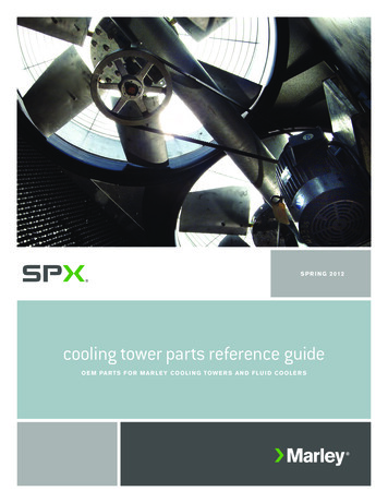
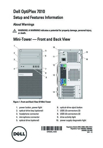
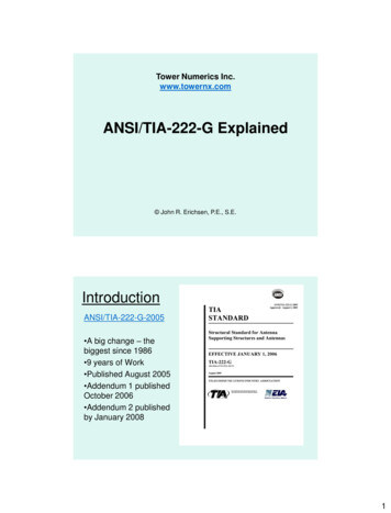
275 Battery Street, Suite 1050San Francisco, California s.com040402.2393.9400400391.9395Barbed Wire Fence390390395.2392.7EXISTING .9390392.5389.8389.7389.8392.4393.2General Services AgencyCapital Programs1401 Lakeside DriveOakland CA, 94612393.9NEWFIREARM M-DD395.93A-20155'-0"391.3389.9EXISTING "EXISTING STORAGECONTAINERSUPNEW TACTICALTRAINING RICALPANEL390EXISTINGCHAINLINK FENCEN(E) CBGRATE 387.6Inv XP. 08-31-21ROFTONATEASPHALT389.9ELECTRIC BOXROADWAYACL PATCHE N LA S A . D I TAGVI389.3389.3NOITCRUTSS ED A RC HTEC S389.3PROFESSIONAL SEALSNI389.0388.2L388.51A-201IDO CU(E) CBGRATE 387.8Inv 381.75388.9ELEC BOX(E) UTILITY BOXD:\documents\Projects\ACSO Training Tower\2021007.Alameda County Fire Training Tower.rvtKEY PLAN389.1TOWER SUPPORT8/24/2021 6:40:38 PM390389.6EXISTINGGARAGESTCopyright 2015 AE3 PARTNERS All Rights Reserved - These Plans and/or Specifications are intended for the sole benefit of AE3 Partners client and may not be copied, reproduced, used or reused in any form without the express written consent of AE3Partners.EXISTINGEASTPORTABLE4A-201O F C A L I FORFACILITYEnter address hereEnter address hereEnter address hereEXISTING GENERAL SERVICES BUILDING1PROJECTPROJECT NAMESITE PLAN1" 20'-0"SHEET TITLESITE PLANDRAWN BY REV'D BYSHEET NUMBERAuthor ApproverPROJECT NUMBERAddendum 2 Attachment 2Project NumberDATEIssue DateA-001
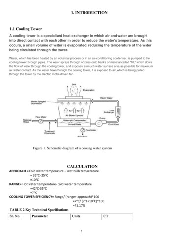
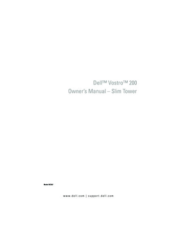
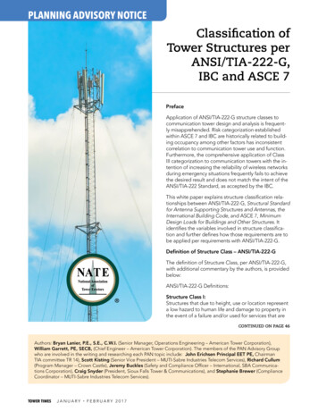
EXISTING BUILDING32'-0"NEW PREMANUFACTURED TRAINING TOWER22'-9 3/4"24'-0"275 Battery Street, Suite 1050San Francisco, California s.comROOF40'-0"LEVEL 0430'-0"LEVEL 0320'-0"LEVEL 0210'-0"LEVEL 010"4EAST1/8" 1'-0"44'-0"NEW PREMANUFACTURED TRAINING TOWER46'-9 3/4"50'-0"49'-4"EXISTING PORTABLE STORAGE CONTAINER40'-0"ROOF40'-0"LEVEL 0430'-0"General Services AgencyCapital Programs1401 Lakeside DriveOakland CA, 94612LEVEL 0320'-0"LEVEL 0210'-0"YYYY-MM-DDISSUE/REVISIONNO.LEVEL 010"3NORTH1/8" 1'-0"EXISTING ARMORY BUILDING58'-0"NEW PREMANUFACTURED TRAINING TOWER22'-9 3/4"8'-0"ROOF40'-0"LEVEL 0430'-0"LEVEL 010"PROFESSIONAL SEALSNOITCRUTSS ED A RC HLNNO.C-28047OCEXP. 08-31-21ROFTONSEE MANUFACTURER'S SPECIFICATIONSTEROOF40'-0"A50'-0"EXISTING ARMORY BUILDING44'-0"NI49'-0"NEW PREMANUFACTURED TRAINING TOWER46'-9 3/4"E N LA S A . D I TAGVIEXISTING BUILDING40'-0"WEST1/8" 1'-0"IDO CU2NTEC SD:\documents\Projects\ACSO Training Tower\2021007.Alameda County Fire Training Tower.rvtKEY PLANA8/6/2021 11:19:41 AMLEVEL 0210'-0"STCopyright 2015 AE3 PARTNERS All Rights Reserved - These Plans and/or Specifications are intended for the sole benefit of AE3 Partners client and may not be copied, reproduced, used or reused in any form without the express written consent of AE3Partners.LEVEL 0320'-0"O F C A L I FORFACILITYEnter address hereEnter address hereEnter address hereLEVEL 0430'-0"PROJECTPROJECT NAMELEVEL 0320'-0"SHEET TITLELEVEL 0210'-0"SITE ELEVATIONSDRAWN BY REV'D BYSHEET NUMBERAuthor ApproverLEVEL 010"PROJECT NUMBERProject Number1SOUTH1/8" 1'-0"Addendum 2 Attachment 2DATEIssue DateA-201
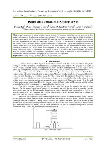
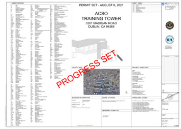
275 Battery Street, Suite 1050San Francisco, California s.com45 Fremont Street, 28th floorSan Francisco, CA 94105415.989.1004 kpff.comSEOR Contact:david.rossi@kpff.comDay-to-Day Contact:brian.biehl@kpff.comALAMEDA COUNTY FIRE TRAINING TOWERDUBLIN, CABIM 360://2100123-00 Alameda County Fire Training Tower/2100123 ALAMEDA COUNTY FIRE TRAINING TOWER KPFF-R2019.rvt7/30/2021 5:19:43 PMSYMBOLSF.O. edGrade BeamGlued Laminated BeamGlued Laminated DBRGBRKTBTWNB.U.BalanceBottom LowerBuildingBlockBlockingBeamBottom ofBottomBreak PointBoardBearingBracketBetweenBottom izontalHigh PointHard RockHollow Structural ONSTRCONTINC.J.P.CTRCTRDCTRSNKChannelCalifornia Building CodeCast In PlaceConstruction or Control JointCeilingCenter LineClearConcrete Masonry Complete Joint A orDIAGDIMDLDNdoD.W.F.DWGPenny weightDoubleDepressionDouglas FirDiameterDiagonalDimensionDead LoadDownDittoDeformed Wire NGRE.O.E.O. MASE.O. PLE.O. SLABEQEQPTE.W.EXPEXTExistingEachEach FaceExpansion JointElevationElectricalElevatorEmbedmentEdge NailEnclosureEngineerEdge ofEdge of MasonryEdge of PlateEdge of SlabEqualEquipmentEach WayExpansionExteriorF.D.FDNF.F.FINFLRF.O.F.O. CONCF.O. MASFloor DrainFoundationFinish FloorFinishFloorFace ofFace of ConcreteFace of MasonryFace of StudFramingFar SideFoot or FeetFootingII.D.I.F.INFOINSULINTMoment of InertiaInside DiameterInside PSKSF1000 PoundsKIPS Per Square ndsLive LoadLong Leg HorizontalLong Leg VerticalLongitudinalLow PointLow ShrinkageLaminated Strand LumberLightLaminated Veneer LumberLight LMachineMasonryMaterialMaximumMachine BoltMiscellaneous ChannelMid-depthMechanicalMoment .I.C.NO.N.P.N.S.N.T.S.NewNot ApplicableNot In ContractNumberNo ProfileNear SideNot To Scaleo.c.O.D.O.F.O.H.OPNGOPP.OSBO.W.S.G.O.W.S.J.On CenterOutside DiameterOutside FaceOpposite HandOpeningOppositeOriented Strand BoardOpen Web Steel GirderOpen Web Steel ound per Cubic FootPowder Driven FastenerPowder Driven PinProperty Line or ds per Linear FootPlywoodPlywoodPartial Joint PenetrationPounds per Square FootPounds per Square InchParallel Strand LumberPost-TensionedPressure TreatedPressure Treated Douglas FirRR.D.RDWDREFREINFREQDREVRFRMR.O.RadiusRoof ofRoomRough AGGSTDSTIFFSTLSTRUCTSYMSection ModulusSee Architectural DrawingsSee Civil DrawingsScheduleSee Electrical DrawingsSquare FeetSheetSheathingSimilarShrinkage Joint, Seismic Joint or Slip JointSee Landscape DrawingsSee Mechanical DrawingsSpecial Moment FramesSheet Metal ScrewSlab On GradeSpace or SpacingSee Plumbing DrawingsSpecificationSquareSee Structural ymmetricT & BT & GT.B.THKTHRUT.L.T.O.T.O.T.S.T.O. CONCT.O. PART.O. PLYT.O. PLT.O. SLABT.O. STLTRANSTST.U.TYPTop and BottomTongue and GrooveTie BeamThickThroughTop LowerTop OfTop of Topping SlabTop of ConcreteTop of ParapetTop of PlywoodTop of PlateTop of SlabTop of SteelTransverseTube SteelTop UpperTypicalUBCU.N.O.Uniform Building CodeUnless Noted OtherwiseV.B.VENTVERTV.I.F.Vapor BarrierVentilationVerticalVerify In FieldWw/w/oWDWFW.P.W.P.J.WTW.W.F.Wide FlangeWithWithoutWoodWide FlangeWork PointWeakened Plane JointWeight or Structural TWelded Wire FabricSECTIONREFERENCE:DETAIL NUMBER2S3.4DETAILREFERENCE:S3.4WALLSECTION:2DETAIL NUMBERSHEET TION:2SHEET NUMBERS3.4DETAILREFERENCE:SHEET INDEXWALLELEVATION:1REVISION NUMBERMATERIALSSHOWN ONPLANS:22S3.4S3.4REVISION SHEET NUMBERRS-12CAST-IN-PLACE CONCRETEPRECAST CONCRETE#PERMIT SETAnchor BoltAmerican Concrete InstituteArea DrainAdditionalAdjacentAbove Finish FloorAmerican Institute of Steel ConstructionAlternateApproximatelyArchitect or ArchitecturalAsphaltAmerican Society for Testing and MaterialsAsphaltic Concrete, Air ConditionGeneral Services AgencyCapital Programs1401 Lakeside DriveOakland CA, 94612ISSUE LOGTITLES-001 TITLE PAGE S-101 GENERAL NOTES S-201 FOUNDATION PLAN S-301 FOUNDATION DETAILS ISSUE/REVISIONNO.YYYY-MM-DDCONCRETE MASONRY UNITSBRICK MASONRY UNITSSTEEL MEMBERSWOOD OR METAL STUDSMATERIALSSHOWN ONDETAILS:CONCRETEMASONRY UNITSIN PLANCAST-INPLACECONCRETEIN SECTIONPRE-CAST ORC.I.P. CONCRETEIN ELEVATIONPRE-CASTCONCRETEINSECTIONCONCRETEMASONRY UNITSIN SECTIONCMU ORBRICKIN ELEVATIONBRICKMASONRY UNITSIN SECTIONKEY ESECTIONANGLESECTIONMETALSTUD ORJOIST' 'WOOD STUDOR JOISTSTUD KINGROCKGLU-LAMSECTIONTRUSSJOISTEARTHPROFESSIONAL SEALSISSUE LOG KEYISSUED AS PART OF A SET' — 'NOT A PART OF ISSUED SET' * 'ISSUED FOR INFORMATION ONLY' o 'PREVIOUSLY SUBMITTED FOR PLAN CHECK& PROVIDED FOR INFORMATION RCHASPHASTMA.C.SHEET INDEXDATECopyright 2015 AE3 PARTNERS All Rights Reserved - These Plans and/or Specifications are intended for the sole benefit of AE3 Partners client and may not be copied, reproduced, used or reused in any form without the express written consent of AE3 ter address herePROJECTALAMEDA COUNTY FIRE TRAINING TOWERSHEET TITLETITLE PAGEDRAWN BY REV'D BYSHEET NUMBERAuthor ApproverPROJECT NUMBER2100123.00Addendum 2 Attachment 2DATE07-30-2021S-001
GENERALNOTESGENERALFOUNDATIONSCONCRETE WORKSTRUCTURAL STEEL AND MISCELLANEOUS IRONDimensions refer to rough concrete surfaces, face of studs, face of concrete block, top ofsheathing, or top of slab, unless otherwise indicated. The Contractor shall verify alldimensions prior to the start of construction. The Architect shall be notified of anydiscrepancies or inconsistencies.Foundations conform to the recommendations of the Geotechnical Report entitled: "ASCO RTCTower Project 5301 Madigan Road Dublin, California" prepared by Cal Engineering & Geology,dated December 2nd, 2019.Forms shall be properly constructed conforming to concrete surfaces as shown on thedrawings, sufficiently tight to prevent leakage, sufficiently strong, and braced tomaintain their shape and alignment until no longer needed to support the concrete. Formsfor exposed concrete shall be plywood, using sheets as large as possible, with all jointstightly fitted and blocked, and shall produce a finished concrete surface which is smooth,true, and free from blemishes according to accepted standards for architectural concrete.Anchor BoltsAll drawings are considered to be a part of the contract documents. The Contractor shall beresponsible for the review and coordination of all drawings and specifications prior to thestart of construction. Any discrepancies that occur shall be brought to the attention of theArchitect prior to the start of construction so that a clarification can be issued. Any workperformed in conflict with the contract documents or any code requirements shall be correctedby the Contractor at his own expense and at no expense to the owner or Architect.Notes and details on the structural drawings shall take precedence over general notes andtypical details. Where no details are given, construction shall be as shown for similarwork.All work shall conform to the minimum standards of the following codes:2019 California Building Code, which comprises Title 24, Part 2 of the California Code ofRegulations, as adopted by the California Building Standards Commission referred to here as"The California Building Code, 2019 Edition" or "the code", and any other regulating agencieswhich have authority over any portion of the work, including the State of California Divisionof Industrial Safety, and those additional codes and standards including, but not limited to,the following incorporated codes listed below, and in these structural notes andspecifications.American Society of Civil Engineers: ASCE 7-16 Minimum Design Loads for Buildings and OtherStructures including Supplement No. 1 and 2.American Concrete Institute (ACI): ACI 318-14 Bldg. Code Requirements for Structural Concreteand Requirements for Structural Concrete and CommentaryAmerican Institute of Steel Construction (AISC): Steel Construction Manual 15th EditionAmerican Institute of Steel Construction (AISC): AISC 341-16 Seismic Provisions forStructural Steel BuildingsMaximum soil pressure 4500 psf DL LL6000 psf DL LL LateralCoefficient of friction 0.32Passive earth pressure 350 pcfThe Contractor shall provide for the design and installation of all cribbing, sheathing,and shoring required and shall be solely responsible for all excavation proceduresincluding lagging, shoring, and the protection of adjacent property, structures, streets,and utilities in accordance with all national, state, and local safety ordinances.FootingsFootings shall extend to such depth as to bear upon firm, undisturbed native soil orengineered fill. All abandoned footings, utilities, etc. shall be removed. All footingsshall be founded at a depth at least 24 inches below the lowest adjacent grade. Footingdepths shown on the structural drawings are minimum depths. Footings may be poured in neatexcavated trenches.Excavations for footings shall be observed by the Geotechnical Engineer prior to placingreinforcing and concrete. The Contractor shall notify the Geotechnical Engineer when theexcavations are ready for observation.Engineered FillEngineered fill below footings shall be compacted to 90% relative compaction as determinedby the ASTM D1557 compaction test method and under the observation of the GeotechnicalEngineer.Slabs On GradeAmerican Institute of Steel Construction (AISC): AISC 360-16 Specification for StructuralSteel BuildingsAmerican Welding Society: AWS D1.1:2015 Structural Welding Code - SteelAmerican Welding Society: AWS D1.3:2008 Structural Welding Code - Sheet SteelFor the sub capillary break materials under concrete slabs on grade, refer to theGeotechnical Report. Provide a 15 mil vapor barrier complying with ASTM E1745 Class A witha WVTR less than or equal to 0.008 per ASTM E96, placed in accordance with ASTM E1643 over4" rock course under slabs on grade. Rock course shall be rolled to a smooth surface.American Welding Society: AWS D1.4:2017 Structural Welding Code - ReinforcingBackfillAmerican Welding Society: AWS D1.8:2016 Structural Welding Code - Seismic SupplementAll excavations shall be properly backfilled. Do not place backfillbefore the concrete or grout has attained full design strength. Theor protect all building and pit walls below grade from lateral loadsfloors are completely in place and have attained full strength. Theprovide for the design, permits, and installation of such bracing.ASTM specifications on the structural drawings shall be of the latest version, unlessotherwise noted.behind retaining wallsContractor shall braceuntil the attachingContractor shallRefer to the architectural drawings for the following:Dimensions not shown on the structural drawings.Size and location of all floor and roof openings, except as noted.Size and location of all interior and exterior non-bearing partitions.Size and location of all door and window openings, except as noted.Size and location of inserts for cladding or ornamentation.Size and location of all concrete curbs, equipment pads, pits, floor drains, slopes,depressed areas, change in level, chamfers, grooves, inserts, etc.Floor and roof finishes.Refer to the mechanical, plumbing, and electrical drawings for the following:Pipe runs, sleeves, hangers, trenches, wall and slab openings, etc., except as noted.Electrical conduit runs, boxes, and outlets in walls and slabs.Concrete inserts for electrical, mechanical, or plumbing fixtures.Size and location of machine or equipment bases or anchor bolts for motor mounts.The contract structural drawings and specifications represent the finished structure. Theydo not indicate the method of construction. The Contractor shall provide all measuresnecessary to protect the structure during construction. Such measures shall include, but notbe limited to, bracing and shoring for loads due to construction equipment, etc. Observationvisits to the site by the Engineer shall not include inspection of the aforementioned items.Contractor shall investigate the site, during clearing and earthwork operations, for filledexcavations or buried structures, such as cesspools, cisterns, foundations, etc. If any suchstructures are found, the Engineer shall be notified immediately.Openings, pockets, etc., larger than 6" shall not be placed in concrete slabs, decks, orwalls, unless specifically detailed on the structural drawings. Notify the Engineer whendrawings by others show openings, pockets, etc., larger than 6" not shown on the structuraldrawings, but which are located in structural members. For any further restrictions onopenings in structural elements, see applicable sections below.Footing backfill and utility trench backfill within the building area shall be mechanicallycompacted in layers in accordance with the Geotechnical Report and observed by theGeotechnical Engineer or Inspector. Flooding will not be permitted.Geotechnical Engineer Observation LetterThe Geotechnical Engineer shall prepare a letter for the Building Department giving anopinion regarding conformance of the footing excavations, engineered fill compaction,subgrade preparation, and backfilling with the requirements contained in the GeotechnicalReport.REINFORCING STEELReinforcing Steel detailing, fabrication, and placement shall conform to the "CaliforniaBuilding Code", Chapter 19; the "Manual of Standard Practice of the Concrete ReinforcingSteel Institute", latest edition; and the "Building Code Requirements for StructuralConcrete and Commentary", ACI 318-14; unless otherwise noted.Standards:Reinforcing steel shall conform to the following standards:Refer to architectural, electrical, and mechanical drawings for details at door and windowopenings, floor type hinges, etc., and for location of sleeves, pipes, and other embeddeditems. Openings through slabs or walls not shown on the structural drawings which wouldinterrupt reinforcing bars shall not be made without approval of the Architect.BIM 360://2100123-00 Alameda County Fire Training Tower/2100123 ALAMEDA COUNTY FIRE TRAINING TOWER KPFF-R2019.rvtCopyright 2015 AE3 PARTNERS All Rights Reserved - These Plans and/or Specifications are intended for the sole benefit of AE3 Partners client and may not be copied, reproduced, used or reused in any form without the express written consent of AE3 Partners.7/30/2021 5:19:44 PMSpecifications and detailing of all waterproofing and drainage items, although sometimesindicated on the structural drawings for general information purposes only, are solely thedesign responsibility of others.Shop drawings, special inspections, and material sampling and testing, when required, arespecified in their respective tables in the general notes and in the specifications.Headed Reinforcement: Where noted on plans, provide rebar terminators capable ofdeveloping the tensile strength of the reinforcing steel. Rebar terminators shall be asmanufactured by Erico Inc (IAPMO ES ER-0188) or approved equal with a current evaluationreport from an approved source.Form Saver: Form savers are to be used where noted on the drawings. In addition, formsavers may be substituted in lieu of dowels at construction joints. Where substituted,contractor to submit for review prior to construction. Form savers shall be capable ofdeveloping at least 125% of the specified yield strength of the reinforcing steel. Formsavers shall be Type 2, as per ACI 318-14 Section 18.2.7. Form Savers shall be asmanufactured by Erico Inc (IAPMO ES ER-0129) or approved equal with a current evaluationreport from an approved source.DESIGNDesign conforms to the California Building Code, 2019 EditionLive loads:Roof (flat) .Floor Live Load .100 psf100 psfWind Analysis:Basic wind speed, V3S .Exposure .Internal Pressure Coefficient, GCPI .Seismic Analysis:Seismic Importance Factor, I .Risk Category .Site Location, Latitude .Site Location, Longitude .(CBC Figure 1609)(CBC Section 1609.4.3)(ASCE Table 26.13-1)VULT GCPI (ASCE Table 1.5-2)(CBC Table 1604.5)(CBC(CBC(CBC(CBC(CBC(CBCLateral System (ASCE Table 12.2-1).Moment Frame System,Steel Ordinary Moment FrameR 3.5ΩO 3Cd 3Lateral System (ASCE Table 12.2-1).Response Modification Factor, .System Overstrength Factor,.Deflection Amplification Factor.1.0II38.6990 -122.8368 Spectra Accel., Short Period, SS .Spectra Accel., Long Period, S1 .Site Classification .Design Response, Short Period, SDS.Design Response, Long Period, SD1 .Seismic Design Category .Response Modification Factor, .System Overstrength Factor,.Deflection Amplification Factor.I 92 mphC 0.18Figure 1613.2.1(1))SSFigure 1613.2.1(2))S1Section 1613.2.2)SDSSection 1613.2)Section 1613.2)SD1Table 1613.2.5(1)&(2)) 1.614 g0.60 gD1.076 gNULLDBuilding Frame SystemSteel Ordinary Concentric Braced FrameR 3.25ΩO 2Cd 3.25Welding: Where welding of reinforcing bars is approved by the Engineer, it shall be doneby AWS certified welders using E80XX or approved electrodes. Welding procedures shallconform to the requirements of the "Structural Welding Code - Reinforcing Steel", AWS-D1.4Clear distances, steel to forms, unless noted otherwise:Slabs not exposed to weather, joists, interior wall surfaces .3/4"Exterior wall surfaces, slabs exposed to weather, #5 and smaller .1-1/2"Exterior wall surfaces, slabs exposed to weather, #6 and larger .2"Clear distance between bars .2"Slabs on rolled grade .1-1/2"Formed surfaces in contact with earth .2"Unformed surfaces in contact with earth .3"Shop drawings shall be submitted to the Architect for review prior to fabrication. Shopdrawings shall include elevations of all beams and columns showing bar and lap locations.See Shop Drawing Submittal Requirements elsewhere in General Notes. Submit millcertificates for reinforcing steel prior to rebar placement.SEOR Contact:david.rossi@k
fixt fixture fl floor flash flashing fluor fluorescent fo face of fof face of finish . incan incandescent insul insulation int interior jan janitor jct junction jst joist jt joint okit kitchen . ul underwriters laboratories, inc