Transcription
Tower Numerics Inc.www.towernx.comANSI/TIA-222-G Explained John R. Erichsen, P.E., S.E.IntroductionANSI/TIA-222-G-2005 A big change – thebiggest since 1986 9 years of Work Published August 2005 Addendum 1 publishedOctober 2006 Addendum 2 publishedby January 20081
Revision G Philosophy – WhyChange? New Technology– Engineering Theory – LRFD vs. ASD – Explicit Impact Controversial – LRFD is not universally used ASD has not been updated since 1989 A merged LRFD and ASD manual may appear in the future– Computing Resources – Implicit impact Increase computing power allows greatercalculation/programming sophistication– Research – Implicit Impact Bracing capacity - ERI Wind Tunnel Studies - PiRod Greater Understanding of Wind Loads - EUROCODERevision G Philosophy – WhyChange? Building Code Consolidation– Simplify building permit process nationally– Unify the application – Development of the IBC– Consolidation of» SBC» UBC» BOCA2
Revision G Philosophy – WhyChange? Changes in Environmental Loads– New Wind Speed Measurement Techniques Shift from Fastest mph to 3-Second Gust Government Mandated Change– Development of National Ice Loads ASCE-7 ’05 will make ice loads mandatory Study now covers the entire United States– Seismic Loading May govern in very special circumstancesRevision G Philosophy – WhyChange? A desire by the Main Committee to improve buyer/userconfidence– Eliminate the “interpretations” that may not be compatible withtheory or the intent of the standard– Define the rules. Less reliance on “Engineering Judgment”– Acknowledgement that revision F did not always allow theuser/buyer to make a confident competent comparison ofcompeting designs– Raise the bar– Create an International Standard (IASS Moscow Feedback)3
Loads – Different TypeDeveloping a Wind Load Classify the structure by use and risk- Classification will adjust the return period.- How will the structure be used (Ham Operation vs. 911)?- What is the risk to life and Property (Located in a urbanenvironment vs. Rural)? What is the local environment?- Exposure to wind (surface roughness). Exposure Categories: B,C, and D.- Topography (flat or on top of a hill). Topographic Categories 1through 5.4
Return Periods Class I – 25 year return Period– Probability of occurrence in one year 0.04– Importance Factor, I 0.87 Creates a wind pressure that is– 13% less than Class II, (7% decrease in windspeed)– 24% less than Class III (13% decrease in windspeed) Class II – 50 year return Period– Probability of occurrence in one year 0.02– Importance Factor, I 1.00 Creates a wind pressure that is– 13% Greater than Class I, (7% increase in windspeed)– 15% less than Class III, (7% decrease in windspeed) Class III – 100 year return Period– Probability of occurrence in one year 0.01– Importance Factor, I 1.15– Creates a wind pressure that is– 13% Greater than Class II, (7% increase in windspeed)– 24% Greater than Class I (13% increase in windspeed)Exposure Categories – Exposure B Urban and Suburban Wooded Areas Filled with Obstructions the Sizeof Single Family Dwellings Must surround the structure atleast 2,630 ft or 10 times thestructure height in all directionswhichever is greater5
Exposure Categories – Exposure C Open terrain with scattered obstructions havingheights generally less than 30 ft [9.1 m]. This category includes flat, open country,grasslands and shorelines in hurricane proneregions.Exposure Categories – Exposure D Flat, unobstructed shorelines exposed to wind flowing over open water (excluding shorelines inhurricane prone regions) for a distance of at least 1 mile [1.61 km].Shorelines in Exposure D include inland waterways, lakes and non-hurricane coastal areas.Exposure D extends inland a distance of 660 ft [200 m] or ten times the height of the structure,whichever is greater.Smooth mud flats, salt flats and other similar terrain shall be considered as Exposure D.6
Wind Shift from “Fastest mph” to“3-second Gust” windspeed– Government changed themeasurement standard in theearly 1990’s (ASCE 7-95)– Conversion FactorsWind7
WindWind on Ice & Ice Ice map is developed for Glazeonly. It does not include Rime Ice An analytical estimate based uponcomputer modeling and empiricalobservations The Wind on Ice and Ice thicknesslisted cannot be separated. Themodel is based upon a windmechanism that drives iceaccumulation. Lower winds willresult in a different ice thickness andvice versa.8
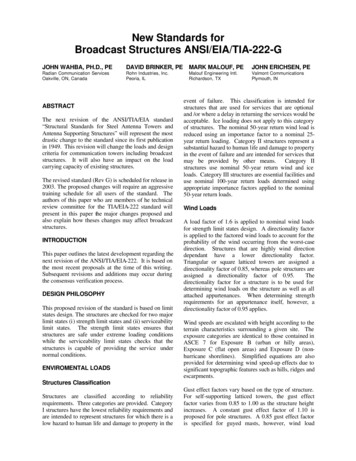
Wind on Ice & Ice1. The importance factors shift the iceloading return periods in the samemanner as the 3-second gust wind speed.2. It is a defined requirement.3. 1/4” ice can be ignored.4. Pay close attention to special windregions indicated by the shaded areas.5. All values represent zones. Nointerpolation.6. Pay attention to the notes in the figure.NorthwestColumbia River BasinLake Superior RegionAlaskaTerrain Features (Topography)EIA Standard has adopted the 5 categories defined by ASCEHowever, the calculations were simplified.Escarpment2-D Ridge or 3-D Axisymmetrical Hill9
Terrain FeaturesCategory 1: No abrupt changes in general topography, e.g. flat or rolling terrain, no windspeed-up consideration shall be required.Category 1 – No Impact,Terrain Features are ignored.Terrain FeaturesCategory 2: Structures located at or near the crest of an escarpment. Wind speed-upshall be considered to occur in all directions. Structures located on the lower half ofan escarpment or beyond 8 times the height of the escarpment from its crest, shall bepermitted to be considered as Topographic Category 1.Structures A & B – Category 1Structures C & D – Category 2Category 1 – No Impact,Terrain Features are ignored.10
Terrain FeaturesCategory 3: Structures located in the upper half of a hill. Wind speed-up shall beconsidered to occur in all directions. Structures located in the lower half of a hill shallbe permitted to be considered as Topographic Category 1.Structures A & B – Category 1Structures C & D – Category 3A hill is a rise fromaverage terrain in alldirections.Category 1 – No Impact,Terrain Features are ignored.Terrain FeaturesCategory 4: Structures located in the upper half of a ridge. Wind speed-up shall beconsidered to occur in all directions. Structures located in the lower half of a ridgeshall be permitted to be considered as Topographic Category 1.Structures A & B – Category 1Structures C & D – Category 4A ridge is a rise from averageterrain in two directions.Category 1 – No Impact,Terrain Features are ignored.11
Terrain FeaturesCategory 5: Wind speed-up criteria based on a site-specific investigation.For topographic category 5, Kzt shall be based on recognizedpublished literature or research findings.Use IBC or ASCE 7-0512
Topographic FeaturesEscarpmentHillRidgeDefault Environmental ValuesAs listed inANNEX A: PROCUREMENT AND USERGUIDELINES Default Structure Class: II Exposure Category C Topographic Category 1 Assume the guy elevations are equal to thebase elevation Default Seismic Site Class D (Stiff Soil)13
Antenna Loads Area calculations derived utilizing a standardized approachLess latitude for the designer.Must include antenna pipes – Depends on the direction underconsideration Design Wind Force on Appurtenances–The design wind force on appurtenances (either discrete or linearbut excluding microwave antennas), FA, shall be determined fromthe equation:–FA qz Gh (EPA)A–Where (EPA)A Ka[(EPA)N cos2( ) (EPA)T sin2( )]–– (EPA)N (Ca AA)N(EPA)T (Ca AA)TEquivalent flat plate areas based on Revision C of this Standard shall bemultiplied by a force coefficient, Ca, equal to 2.0 except when theappurtenance is made up of round members only, a force coefficient of1.8 may be applied.Appurtenances14
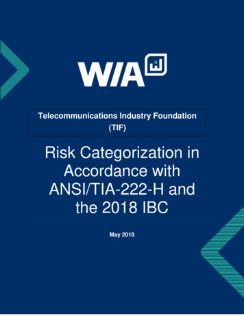
AppurtenancesWind Speed Domains Subcritical – Reynolds Numbers, Re 2.78 x 10⁵Transitional - 2.78 x 10⁵ Reynolds Numbers, Re 5.56 x 10⁵Supercritical – Reynolds Numbers, Re 5.56 x 10⁵SubcriticalSupercritical15
Windspeed Domain – Subcritical toTransitional to SupercriticalExposure BWindspeed Domain – Subcritical toTransitional to SupercriticalExposure C16
Windspeed Domain – Subcritical toTransitional to SupercriticalExposure DAppurtenancesDefined Default Cellular Antenna Areas for bidsIceti 0.50”[ti 13 mm]No iceIce0.50” ti 1.50”[13 ti 38 EPA)Aft2[m2]Wtkips[kN]Light(9 antennas max)55 [6.5]0.75 [3.3]75 [7.9]1.00 [3.3]110 [10.2]1.50 [6.7](9) 1 5/8 in. diameter(2.0 in. [51 mm] OD)Heavy(12 antennas max)80 [8.4]1.20 [5.3]100 [9.3]1.20 [5.3]135 [12.6]2.00 [8.9](12) 1 5/8 in. diameter(2.0 in. [51 mm] OD)Carrier TypeTransmissionLines17
Line Loads LINE LOADS CAN NO LONGER BECONSIDERED AS PART OF THESECTION AREA! It is an appurtenance. No longer adistinction between discrete and linear The designer will utilize the same forcecoefficients, Ca, factors that are applied toantennas, and other “discrete”appurtenances.Line LoadsSheltering: Based upon voids ratio (1- ) Only applicable to sub-critical flow. Sheltering effects allowed when the line loads are entirely on the inside of thestructure or is outside the cross section of the and entirely within the face zone.Triangular Cross SectionSquare Cross Section18
Line Clusters(EPA)A Ka[(EPA)N cos2( ) (EPA)T sin2( )]Can be treated asindividual lines.Must treat asrectangular lineclusters utilizing(EPA)A ApproachLines and Monopoles Section 2.6.9.1.2Note: In the absence of a detailed transmission line layout andinstallation bend radii of the lines, the minimum diameter of apole structure shall not be less than the diameter which results in45% utilization of the cross-section for the placement of internaltransmission lines.USE INTERPRETATION A !Remember: “In the absence of a detailed transmission linelayout and installation bend radii of the lines”19
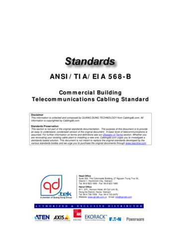
Mount Loads Mount loads will be defined and calculation procedures are established. Divided into broad approaches– Mounting Frames– Symmetrical Frame/Truss Platform– Low Profile Platform– Symmetrical Circular Ring Platform– (EPA)A Ka[(EPA)N cos2( ) (EPA)T sin2( )] -Mounting FramesMOUNTING FRAME(TYP)0.75 REDUCTION FACTOR NOT ALLOWEDMOUNTING FRAME(TYP)Ka 0.8 can be applied toantennas and antennamounting pipes mountedon the SymmetricFrame/Truss Platform.Subcritical Flow Only!A reduction ofthe structureforces is notallowed0.75 REDUCTION FACTOR APPLIES(MINIMUM OF 3 MOUNTING FRAMES REQUIRED)Figure 2-6: Multiple Mounting Frames20
Ka 0.8 can be applied toantennas and antennamounting pipes mountedon the SymmetricFrame/Truss Platform.Subcritical Flow Only!A reduction ofthe structureforces is notallowed(TRUSS TYPE)Figure 2-7: Symmetrical Frame/Truss PlatformsKa 0.8 can be applied toantennas and antennamounting pipes mountedon the SymmetricFrame/Truss Platform.Subcritical Flow Only!A reduction ofthe structureforces is notallowedFigure 2-8: Low Profile Platforms21
Ka 0.8 can beapplied to antennasand antennamounting pipesmounted on theSymmetricFrame/TrussPlatform. SubcriticalFlow Only!A reduction ofthe structureforces is notallowedFigure 2-9: Circular Ring PlatformsMounts – Universal Issues Notes for all mounting frame/platformtypes:– Ka shall equal 1.0 for antennas and antennamounting pipes under transitional orsupercritical flow conditions.– Grating and other horizontal working surfacesneed not be included in the effective projectedarea.22
ShieldingKa 1.0 if the shieldingprincipals listed are tobe applied.Seismic Loads New Section – A response to changes in building codesand a greater understanding of how seismic loads occur.23
Seismic – Earthquake Loads Based upon––––Site Classification – Ignored for Site Class IStructure irregularitiesNot required if the Short Period (Ss) is less than 1.00.Not required for structure there is a structural irregularity andwhen the equivalent seismic base shear is less the 50% of the50 year return period wind loading.24
Structure IrregularitiesTypeDescriptionTorsional IrregularityCenter of mass of a section includingappurtenances is offset from the verticalalignment of the structure by more than30% of the smallest plan dimension of thesection.Stiffness IrregularityAverage bending stiffness of a section(IS/LS) varies by more than 50% from anadjacent section.Mass IrregularityMass per unit length (MS/LS) of a sectionincluding appurtenances varies by morethan 200% from an adjacent section.Where: IS average moment of inertia of a sectionMS total mass of a sectionLS length of a sectionNotes:1.A section of a structure shall be considered as the portion between leg connectionsfor latticed structures and the distance between splices in tubular pole structures, not toexceed 50 ft [15 m] for any structure.2.The mass and stiffness of guys for guyed masts shall be excluded when determiningirregularities.3.Torque arms, star mounts, etc. shall not be considered as a stiffness irregularity.4.Mounting frames, antenna mounts, platforms, etc, shall not be considered as astiffness irregularity.Seismic Analysis Procedure MethodsAnalysis Procedure MethodDescription 1Height Limitations on Analysis Procedure MethodsNo mass or stiffness irregularitiesper Table s per Table 2-9PolesLatticed100 ft[30 m]No LimitN/AN/A1500 ft[457 m]No LimitNo LimitN/A200 ft[61 m]600 ft[183 m]N/AModal Analysis,Method 3 in accordance with2.7.9No LimitNo LimitN/ANo LimitNoLimitN/ATime-History Analysis,Method 4 in accordance with2.7.10No LimitNo LimitNo LimitNo LimitNoLimitNoLimitLatticedEquivalent Lateral Force,Method 1 in accordance with2.7.750 ft[15 m]Equivalent Modal Analysis,Method 2 in accordance with2.7.8Self-SupportingGuyedMasts 2GuyedMasts 2PolesNotes:1.Vertical seismic forces may be ignored for Methods 1, 2 & 3.2.Method 4 shall be used when the horizontal distance from the base of the structure to any guyanchor point exceeds 1000 ft [305 m].25
Se
ANSI/TIA-222-G-2005 A big change – the biggest since 1986 9 years of Work Published August 2005 Addendum 1 published October 2006 Addendum 2 published by January 2008 . 2 Revision G Philosophy – Why Change? New Technology –Engineering Theory – LRFD vs. ASD – Explicit Impact Controversial – LRFD is not universally used ASD has not been updated since 1989 .File Size: 2MBPage Count: 44Explore furtherClassification of Tower Structures per ANSI/TIA-222-G, IBC .www.tirap.orgTIA-222 - Structural Standard for Antenna Supporting .standards.globalspec.comANSI/TIA-222 Telecommunication Towerswww.tirap.orgClassification of Tower Structures per ANSI/TIA-222-G, IBC .wia.orgUsing ANSI/TIA 222-G in TOWER and PLS-POLEwww.powline.comRecommended to you based on what's popular Feedback