Transcription
INSTRUMENTATION AND CONTROLTUTORIAL 2 – SENSORS AND PRIMARY TRANSDUCERSThis tutorial provides an overview of instrument sensors used in process and automaticcontrol. It is useful to anyone studying measurement systems and instrumentation but it isprovided mainly in support of the EC module D227 – Control System Engineering. Thistutorial is mainly descriptive.Control is a broad concept and the following might apply to an automated system such asa robot or to a process control system such as a pneumatic valve controlling the flow ofsteam in a pipe.On completion of this tutorial, you should be able to do the following. Explain a basic measurement system. Explain the basic working principles of a variety of temperature sensors. Explain the basic working principles of a variety of pressure sensors. Explain the basic working principles of a variety of speed transducers. Explain the basic working principles of a variety of flow meters. Explain the basic working principles of a variety of force gauges. Explain the basic working principles of a variety of displacement gauges. Explain the basic working principles of a variety of level (depth) gauges. Explain in some detail the theory and use of strain gauges.In order to complete the theoretical part of this tutorial, you must be familiar with basicmechanical and electrical science. D.J.Dunn1
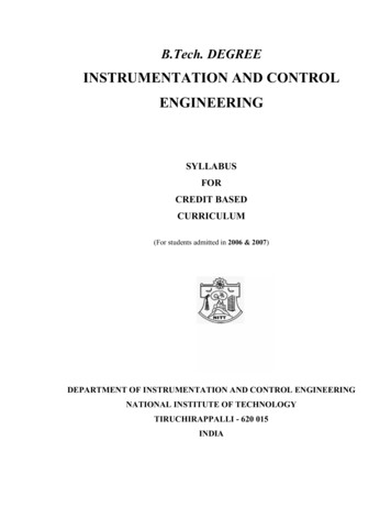
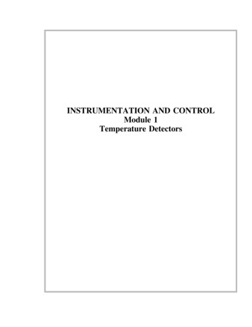
1.INTRODUCTIONA basic instrument system consists of three elements:iiiiiiSENSOR or INPUT DEVICESIGNAL PROCESSORRECEIVER or OUTPUT DEVICEThis tutorial is devoted to input devices but you can never separate it from the rest of the system as in many casesthey are all integral (e.g. a mechanical pressure gauge incorporates all of these elements). A block diagram of abasic system is shown but they are usually more complex.Figure 1Most modern analogue equipment works on the following standard signal ranges. Electric 4 to 20 mA Pneumatic 0.2 to 1.0 barOlder electrical equipment use 0 to 10 V. Increasingly the instruments are digital with a binary digital encoderbuilt in to give a binary digital output. Pneumatic signals are commonly used in process industries for safetyespecially when there is a risk of fire or explosion.The advantage of having a standard range or using digital signals is that all equipment may be purchased readycalibrated. For analogue systems the minimum signal (Temperature, speed, force, pressure and so on ) isrepresented by 4 mA or 0.2 bar and the maximum signal is represented by 20 mA or 1.0 bar.This tutorial is an attempt to familiarise you with the many types of input sensors on the market today. Usuallysuch sensors are called PRIMARY TRANSDUCERS.Things that we commonly measure are:TemperatureSpeedForceStress and StrainMass or WeightSize or VolumePressureFlow rateMovement, Velocity and AccelerationLevel or DepthDensityAcidity/AlkalinitySensors may operate simple on/off switches to detect the following:Objects(Proximity switch)Hot or cold (thermostat)Empty or full (level switch)Pressure high or low (pressure switch)The block diagram of a sensor is shown below.Figure 2 D.J.Dunn2
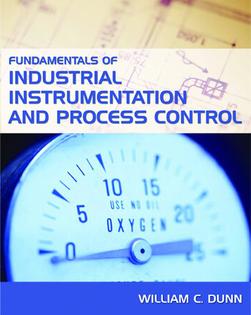
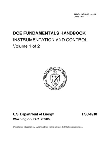
22.1TEMPERATURE TRANSDUCERSTHERMOCOUPLESWhen two wires with dissimilar electrical properties are joined at both ends and one junction is made hot and theother cold, a small electric current is produced proportional to the difference in the temperature. Seebeckdiscovered this effect. It is true no matter how the ends are joined so the cold end may be joined at a sensitivemillivolt meter. The hot junction forms the sensor end.Figure 3The picture shows a typical industrial probe with a flexible extension and standard plug.Figure 4Peltier showed that heat is absorbed at the hot end and rejected at the cold end. Thompson showed that part ofthe e.m.f. is due to the temperature gradient in the wire as well as the temperature difference between thejunctions. Most thermocouple metals produce a relationship between the two temperatures and the e.m.f asfollows.e α(θ1 - θ2) β(θ12 - θ22α and β are constants for the type of thermocouple. The relationship is nearly linear over the operating range.The actual characteristic and suitable operating temperatures depends upon the metals used in the wires. Thevarious types are designated in international and national standards. Typical linear operating ranges are shown forstandard types.It is important that thermocouples are standard so that the same e.m.f will always represent the sametemperature. D.J.Dunn3
Type JType KType TType EType R/SType BType NType L2.20 to 800oC0 to 1200oC-199 to 250oC0 to 600oC0 to 1600oC500 to 1800oC0 to 1200oC0 to 800oCThermocouples come in several forms. They may be wiresinsulated from each other with plastic or glass fibre materials.For high temperature work, the wire pairs are put inside atube with mineral insulation. For industrial uses the sensorcomes in a metal enclosure such as stainless steel.RESISTANCE TYPE SENSORSFigure 5These work on the principle that the electrical resistance of a conductor change with temperature. If a constantvoltage is applied to the conductor then the current flowing through it will change with temperature. The resistivityof the conductor change with temperature. This usually means the resistance gets bigger as the conductor getshotter. The following law relates the resistance and temperature.R Ro(1 αθ)α is the temperature coefficient of resistance. Ro is the resistance at 0oC. Sometimes the equation is given asR Ro(1 αθ - βθ2)A basic temperature sensor is made by winding a thin resistance wire into a small sensor head. The resistance ofthe wire then represents the temperature. This has an advantage over a thermocouple in that it is unaffected by thetemperature of the gauge end. The main type of wire used is PLATINUM. The sensors are usually manufacturedto have a resistance of 100 Ω at 0oC and the value of α is 0.00385 to 0.00390. A typical operating range is 200 to 400oC.A special type of resistance sensor is called a THERMISTOR. They are made from a small piece of semiconductor material. The material is special because the resistance changes a lot for a small change in temperatureand so can be made into a small sensor and it costs less than platinum wire. The temperature range is limited.They are only used for a typical range of -20 to 120oC and are commonly used in small hand held thermometersfor every day use. The relationship between resistance and temperature is of the form R AeB/θ D.J.Dunn4
WORKED EXAMPLE No.1A Platinum resistance thermometer has a resistance of 100 Ω at 0oC and the value of α is 0.00385. Inoperation the resistance is 101 Ω. Calculate the temperature.SOLUTIONRearrange the formula to make θ the subject and evaluate.R 1 105 1R? o 100 12.987 o Ca0.00385WORKED EXAMPLE No.2A thermocouple produces an e.m.f. in mV according to the temperature difference between the sensor tip θ1and the gauge head θ2 such thate α(θ1-θ2) β(θ12-θ22)α 3.5 x 10⁻² and β 8.2 x 10⁻⁶ The gauge head is at 20oC. The mV output is 12 mV. Calculate thetemperature at the sensor.SOLUTION10 0.035(? 1 20) 8.2 x 10 6 (? 12 20 2 )10 0.035? 1 0.7 8.2 x 10 6 ? 12 0.0032810 8.2x10 6 ?12 0.035? 1 0.696728.2 x 10 6 ?12 0.035?1 9.30328 0Solving the quadratic equation yields θ1 251oCSELF ASSESSMENT EXERCISE No.11.A thermocouple produces an e.m.f. in mV according to the temperature difference between the sensor tip θ1and the gauge head θ2 such that e α(θ1-θ2) β(θ12-θ22)Given α 3.5 x 10⁻² and β 8.2 x 10⁻⁶ determine the mV output when the tip is at 220oC and thegauge head at 20oC.(Answer 7.394 mV)2.Describe the basic construction of a resistance type temperature sensor and state the reason why it isunaffected by the temperature of the gauge head.3.State two reasons why instrument systems use standard transmission signal of either 4 - 20 mA or 0.2 - 1bar. D.J.Dunn5
2.3LIQUID EXPANSION and VAPOUR PRESSURE SENSORSThese are thermometers filled with either a liquid such as mercury or an evaporating fluid such as used inrefrigerators. In both cases the inside of the sensor head and the connecting tube are completely full. Any rise intemperature produces expansion or evaporation of the liquid so the sensor becomes pressurised. The pressure isrelated to the temperature and it may be indicated on a simple pressure gauge.Ways and means exist to convert the pressure into an electrical signal. The movement may also directly operate athermostat. These instruments are robust and used over a wide range. They can be fitted with electric switches toset off alarms.Figure 62.4BIMETALLIC TYPESIt is a well-known principle that if two metals are rigidly joined together as a two-layer strip and heated, thedifference in the expansion rate causes the strip to bend.Figure 7In the industrial type, the strip is twisted into a long thin coil inside a tube. One end is fixed at the bottom of thetube and the other turns and moves a pointer on a dial. The outward appearance is very similar to the pressuretype. They can be made to operate limit switches and set off alarms or act as a thermostat. (e.g. on a boiler). D.J.Dunn6
2.5GLASS THERMOMETERThe ordinary glass thermometer is also a complete system. Again the bulb is the sensor but the column of liquidand the scale on the glass is the processor and indicator. Mercury is used for hot temperatures and colouredalcohol for cold temperatures.Figure 8The problems with glass thermometers are that they are BrittleMercury solidifies at -40oC.Alcohol boils at around 120 oC.Accurate manufacture is needed and this makes accurate ones expensive.It is easy for people to make mistakes reading them.Glass thermometers are not used much now in industry but if they are, they are usually protected by a shield fromaccidental breakage. In order to measure the temperature of something inside a pipe they are placed inthermometer pockets. D.J.Dunn7
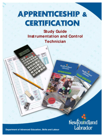
3.PRESSURE TRANSDUCERSPressure sensors either convert the pressure into mechanical movement or into an electrical output. Completegauges not only sense the pressure but indicate them on a dial or scale.Mechanical movement is produced with the following elements. Bourdon Tube. Spring and Piston. Bellows and capsules. Diaphragm.3.1. BOURDON TUBEFigure 9The Bourdon tube is a hollow tube with an elliptical cross section. When a pressure difference exists between theinside and outside, the tube tends to straighten out and the end moves. The movement is usually coupled to aneedle on a dial to make a complete gauge. It can also be connected to a secondary device such as an air nozzleto control air pressure or to a suitable transducer to convert it into an electric signal. This type can be used formeasuring pressure difference. D.J.Dunn8
3.2PISTON TYPEThe pressure acts directly on the piston and compresses the spring. Theposition of the piston is directly related to the pressure. A window in theouter case allows the pressure to be indicated. This type is usually used inhydraulics where the ability to withstand shock, vibration and suddenpressure changes is needed (shock proof gauge). The piston movement maybe connected to a secondary device to convert movement into an electricalsignal.Figure 103.3. CAPSULES AND BELLOWSA bellows is made of several capsules. These are hollow flattenedstructures made from thin metal plate. When pressurised the bellowsexpand and produce mechanical movement. If the bellows is encapsulatedinside an outer container, then the movement is proportional to thedifference between the pressure on the inside and outside. Bellows andsingle capsules are used in many instruments. They are very useful formeasuring small pressures.Figure 113.4DIAPHRAGMSThese are similar in principle to the capsule but the diaphragm isusually very thin and perhaps made of rubber. The diaphragmexpands when very small pressures are applied. The movementis transmitted to a pointer on a dial through a fine mechanicallinkage.Figure 123.5ELECTRICAL PRESSURE TRANSDUCERSThere are various ways of converting the mechanical movement of the preceding types into an electric signal. Thfollowing are types that directly produce an electric signal. Strain Gauge types.Piezo electric types.Other electric effects. D.J.Dunn9
3.5.1STRAIN GAUGE TYPESFigure 13The principles of electric strain gauges are covered later. Strain gauges are small elements that are fixed to asurface that is strained. The change in length of the element produces changes in the electrical resistance. This isprocessed and converted into a voltage. A typical pressure transducer would contain a metal diaphragm whichbends under pressure.3.5.2. PIEZO ELECTRIC TYPESThe element used here is a piece of crystalline material that produces an electric charge on its surface when it ismechanically stressed. The electric charge may be converted into voltage. This principle is used in the pick upcrystal of a record player, in microphones and even to generate a spark in a gas ignitor. When placed inside apressure transducer, the pressure is converted into an electric signal.3.5.3. OTHER ELECTRIC EFFECTSOther electric effects commonly used in transducers are CAPACITIVE and INDUCTIVE. In these cases, thepressure produces a change in the capacitance or inductance of an electronic component in the transducer. Boththese effects are commonly used in an electronic oscillator and one way they may be used is to change thefrequency of the oscillation. The frequency may be converted into a voltage representing the pressure.4. SPEED TRANSDUCERSSpeed transducers are widely used for measuring the output speed of a rotating object. There are many typesusing different principles and most of them produce an electrical output.4.1OPTICAL TYPESFigure 14These use a light beam and a light sensitive cell. The beam is either reflected or interrupted so that pulses areproduced for each revolution. The pulses are then counted over a fixed time and the speed obtained. Electronicprocessing is required to time the pulses and turn the result into an analogue or digital signal. D.J.Dunn10
4.2MAGNETIC PICK UPSFigure 15These use an inductive coil placed near to the rotating body. A small magnet on the body generates a pulse everytime it passes the coil. If the body is made of ferrous material, it will work without a magnet. A discontinuity in thesurface such as a notch will cause a change in the magnetic field and generate a pulse. The pulses must beprocessed to produce an analogue or digital output.4.3TACHOMETERSThere are two types, A.C. and D.C. The A.C. type generates a sinusoidal output. The frequency of the voltagerepresents the speed of rotation. The frequency must be counted and processed. The D.C. type generates avoltage directly proportional to the speed. Both types must be coupled to the rotating body. very often thetachometer is built into electric motors to measure their speed.Figure 16 D.J.Dunn11
5.FLOW METERSThere are many hundreds of types of flow meters depending on the make and application. They may be classifiedroughly as follows. POSITIVE DISPLACEMENT TYPESINFERENTIAL TYPESVARIABLE AREA TYPESDIFFERENTIAL PRESSURE TYPES5.1. POSITIVE DISPLACEMENT TYPESThese types have a mechanical element that makes the shaft of the meter rotate once for an exact known quantityof fluid. The quantity of fluid hence depends on the number of revolutions of the meter shaft and the flow ratedepends upon the speed of rotation. Both the revolutions and speed may be measured with mechanical orelectronic devices. Some of the most common listed below. Rotary piston type.Vane type.Lobe type or meshing rotor.Reciprocating piston typeFluted spiral gear.5.1.1 MESHING ROTORFigure 17The MESHING ROTOR type consists of two rotors with lobes. When fluid is forced in, the rotors turn andoperate the indicating system.5.2. INFERENTIAL TYPE METERSThe flow of the fluid is inferred from some effect produced by the flow. Usually this is a rotor which is made tospin and the speed of the rotor is sensed mechanically or electronically. The main types are : D.J.DunnTurbine rotor typesRotary shunt typesRotating vane typesHelical turbine types12
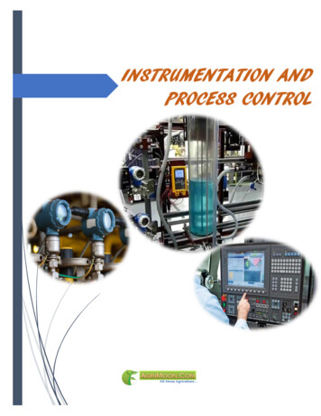
5.2.1 TURBINE TYPEFigure 18The pictures show two industrial flow meters.Figure 19The turbine type shown has an axial rotor which is made to spin by the fluid and the speed represents the flowrate. This may be sensed electrically by coupling the shaft to a small electric tachometer. Often this consists of amagnetic slug on the rotor which generates a pulse of electricity each time it passes the sensor.5.2.2 ROTATING VANE TYPEFigure 20The jet of fluid spins around the rotating vane and the speed of the rotor is measured mechanically orelectronically. D.J.Dunn13
5.3.3. VARIABLE AREA TYPESThere are two main types of this meter Float type (Rotameter) Tapered plug type.5.3.3.1 FLOAT TYPEFigure 21The float is inside a tapered tube. The fluid flows through the annular gap around the edge of the float. Therestriction causes a pressure drop over the float and the pressure forces the float upwards. Because the tube istapered, the restriction is decreased as the float moves up. Eventually a level is reached where the restriction isjust right to produce a pressure force that counteracts the weight of the float. The level of the float indicates theflow rate. If the flow changes the float moves up or down to find a new balance position.When dangerous fluids are used, protection is needed against the tube fracturing. The tube may be made of anon-magnetic metal. The float has a magnet on it. As it moves up and down, the magnet moves a follower andpointer on the outside. The position of the float may be measured electrically by building a movement transducerinto the float.5.3.3.2 TAPERED PLUG TYPE.Figure 22In this meter, a tapered plug is aligned inside a hole or orifice. A spring holds it in place. The flow is restricted asit passes through the gap and a force is produced which moves the plug. Because it is tapered the restrictionchanges and the plug takes up a position where the pressure force just balances the spring force. The movementof the plug is transmitted with a magnet to an indicator on the outside. D.J.Dunn14
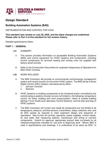
5.4DIFFERENTIAL PRESSURE FLOW METERSThese are a range of meters that convert flow rate into a differential pressure. The important types conform to BS1042 and are ORIFICE METERS.VENTURI METERSNOZZLE METERSPITOT TUBES.The diagram shows a cross section through the four types of d.p. meters.Figure 23The working principle for all these is that something makes thevelocity of the fluid change and this produces a change in thepressure so that a difference p p2 - p1 is created. It can beshown for all these meters that the volume flow rate Q isrelated to p by the following formula.Q K( p)0.5K is the meter constant. A full explanation of these meters iscovered in the tutorials on fluid mechanics. The picture showsan industrial d.p.meter. Extra instrumentation heads can befitted to produce an electrical output (4 – 20 mA) or apneumatic output (0.2 – 1 bar).Figure 24 D.J.Dunn15
WORKED EXAMPLE No.3A Venturi meter has a meter constant of 0.008 m4 N-0.5 s-1. Calculate the flow rate when p 180 PaSOLUTIONQ K( p)0.5 0.008 m4 N-0.5 s-1(180)0.5 0.1073 (m4 N-0.5 s-1)(N 0.5 m-1) or m3/sSELF ASSESSMENT EXERCISE No.2An Orifice meter has a meter constant of 0.004 m4 N-0.5 s-1. Calculate the flow rate when a differentialpressure of 200 Pa is obtained.(Answer 0.0566 m3/s) D.J.Dunn16
6.FORCE SENSORSThe main types of force sensors are Mechanical types.Hydraulic types.Electrical strain gauge types.6.1. MECHANICAL TYPESMechanical types are usually complete measuring systems involving some form of spring such as in a simplespring balance or bathroom scale. It is a basic mechanical principle that the deflection of a spring is directlyproportional to the applied force so if the movement is shown on a scale, the scale represents force.Figure 256.2. HYDRAULIC TYPESHydraulic types are often referred to as hydraulic load cells. The cell is a capsule filled with liquid. When thecapsule is squeezed, the liquid becomes pressurised. The pressure represents the force and may be indicated witha calibrated pressure gauge. The capsule is often a short cylinder with a piston and the pressure produced isgiven by p F/A where F is the force and A the piston area.Figure 26 D.J.Dunn17
6.3STRAIN GAUGE TYPEA typical load cell consists of a metal cylinder with strain gauges fixed to it. When the cylinder is stretched orcompressed, the strain gauges convert the force into a change in resistance and hence voltage. Since the elementsrequire a supply voltage, the cell usually has 4 wires, two for the supply and two for the output.Figure 277.POSITION SENSORSPosition sensors are essential elements in the control of actuators. The position of both linear and rotary actuatorsis needed in robotic type mechanisms. There are three principle types. RESISTIVEOPTICALINDUCTIVE7.1. RESISTIVE TYPESFigure 28A potentiometer is a variable electrical resistance. A length of resistance material has a voltage applied over itsends. A slider moves along it (either linear or rotary) and picks off the voltage at its position or angle. The tracksmay be made from carbon , resistance wire or piezo resistive material. The latter is the best because it gives agood analogue output. The wire wound type produces small step changes in the output depending on how finethe wire is and how closely it is coiled on the track. D.J.Dunn18
7.2OPTICAL TYPESFigure 29Optical types are mainly used for producing digital outputs. A common example is found on machine tools wherethey measure the position of the work table and display it in digits on the gauge head. Digital micrometers andverniers also use this idea. The basic principle is as follows. Light is emitted through a transparent strip or disconto a photo electric cell. Often reflected light is used as shown. The strip or disc has very fine lines engraved onit which interrupt the beam. The number of interruptions are counted electronically and this represents the positionor angle. This is very much over simplified and you should refer to more advanced text to find out how veryaccurate measurements are obtained and also the direction of movement.7.3. INDUCTIVE TYPESFigure 30The most common of these is the Linear Variable Differential transformer or LVDT. The transformer is madewith one primary coil and two secondary coils, one placed above and the other below the primary. The coils areformed into a long narrow hollow tube. A magnetic core slides in the tube and is attached to the mechanism beingmonitored with a non magnetic stem (e.g. brass). A constant alternating voltage is applied to the primary coil. Thisinduces a voltage in both secondary coils. When the core is exactly in the middle, equal voltages are induced andwhen connected as shown, they cancel each other out. When the core moves, the voltage in one secondary coilgrows but reduces in the other. The result is an output voltage which represents the position of the core andhence the mechanism to which it is attached. The output voltage is usually converted into D.C. With suitableelectronic equipment for phase detection, it is possible to detect which direction the core moves and to switch theDC voltage from plus to minus as the core passes the centre position. These can be very accurate and are widelyused for gauging the dimensions of machined components. D.J.Dunn19
8.DEPTH GAUGESDepth gauges measure the depth of liquids and powder in tanks. They use a variety of principles and produceoutputs in electrical and pneumatic forms. The type to use depends on the substance in the tank. Here are a few.Figure 31The ultrasonic system reflects sound waves from the surface and determines the depth from the time taken toreceive the reflected sound. The electronic version uses a variety of electrical affects including conduction of thefluid and capacitance. The pneumatic version bubbles air through the liquid and the pressure of the air is related tothe depth. A simple pressure gauge attached to a tank is also indicates the depth since depth is proportional topressure. D.J.Dunn20
9.STRAIN GAUGESStrain gauges are used in many instruments that produce mechanical strain because of the affect being measured.In their own right, they are used to measure the strain in a structure being stretched or compressed.The strain gauge element is a very thin wire that is formed into the shape shown. This produces a long wire all inone direction but on a small surface area. The element is often formed by etching a thin foil on a plastic backing.The completed element is then glued to the surface of the material or component that will be strained. The axis ofthe strain gauge is aligned with the direction of the strain. When the component is stretched or compressed, thelength of the resistance wire is changed. This produces a corresponding change in the electrical resistance.Let the length of the gauge be L and the change in length be L.The mechanical strain ε L/LLet the resistance of the gauge be R (typically 120 Ω) and the change in resistance be R.The electrical strain ξ R/R.The electrical and mechanical strain are directly proportional and the constant relating them is called the gaugefactor (typically 2).Gauge Factor Electrical Strain/Mechanical strain ξ/ε L R/R LWORKED EXAMPLE No.4A strain gauge is glued to a structure. It has a gauge factor of 2.1 and a resistance of 120.2 Ω. The structureis stressed and the resistance changes to 120.25 Ω. Calculate the strain and convert this into stress.Take E 205 GPaSOLUTION R 120.25 – 120.2 0.05Ωξ R/R1 0.05/120.2 4.16 x 10⁻⁴ε ξ/G 4.16 x 10⁻⁴/2.1 1.981 x 10⁻⁴ σ εE 1.981 x 10-4 x 205 x 109 40.61 MPa D.J.Dunn21
STRAIN GAUGE ARRANGEMENTSA strain gauge is of little use unless we can convert the change in resistance into a voltage. This is best done witha Wheatstone bridge.If only one active gauge is used, this would be R1 or R2. R1and R2 must be equal, so must R3 and R4. In this case, thevoltage at points 1 and 2 are equal to Vs/2 and so the output Vois zero. In order to ensure this, the balancing resistor RB isadjusted to make the output zero with no strain applied to thegauge. Suppose that R1 is the active gauge. If the bridge isbalanced then the voltage at points 1 and 2 is half the supplyvoltage. V1 V2 Vs/2Figure 32When R1 changes its resistance by R the voltage at point 1 becomes:The output becomesVsR/(2R R) (using ratio of resistances)Vo V2 - V1 Vs/2 - VsR /(2R R)Vo Vs R/{(4R 2 R)}Dividing top and bottom by R we getThe gauge factor is defined asVo Vs ( R/R)/{4 2 R/R}G electrical strain/mechanical strainG ( R/R)/ε so ( R/R) GεSubstituting we getVo Vs Gε/{4 2Gε}WORKED EXAMPLE No.5Four strain gauges are formed into bridge with only one active gauge. The nominal resistance of all of them is120 Ω. The gauge factor is 2.1 and the supply voltage is 10 V. Calculate the strain when the output from thebridge is 20 mV.SOLUTIONVo Vs Gε/{4 2Gε} D.J.Dunnε 4Vo G(Vs - 2Vo) (4 x 0.02) {2.1(10 - 0.04)} 3.825 x 10-322
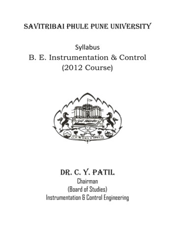
TEMPERATURE EFFECTSOne of the problems with strain gauges is that the resistance also changes with temperature and so it is vital thateach pair of resistors is maintained at the same temperature.If one active gauge is used, say R1, then the other resistor R2must be placed near to it and this is best done by using aDUMMY GAUGE fixed close to the active gauge but in aposition where it is unstrained. Better still, make R2 anotheractive gauge and so double the output from the bridge. Forexample, if a beam is used to produce the strain, one gauge isplaced on top and the other on the bottom as shown. Let R1increase and R2 decrease by R. The voltage at point 1becomesFigure 33The output becomesDividing top and bottom by R we getVs(R - R)/2R (using ratio of resistances)Vo V2 - V1 Vs/2 - Vs(R - R)/2RVo Vs R/{2(2R R)}Vo Vs R/2RVo Vs Gε/2 which is almost double the output.If the load cell only produces tension or compression, the active gauges are R1 and R4 with R2 and R3 beingdummy gauges. All 4 gauges are then at the same temperature. This is shown in the diagram.Figure 34The voltage at point 1 becomesVsR /(2R R)and at point 2 becomesVs(R R)/(2R R)The output becomesVo V2 - V1 Vs R/(2R R)Dividing top and bottom by R we get Vo Vs ( R/R)/{2 R/R}Vo Vs Gε/(2 Gε)This is double the output of a single active gauge and fully temperature stable.If a beam is used in the load cell, all 4 gauges may be madeactive as shown.The output at point 1 becomesV1 Vs(R- R) /2Rand at point 2 becomesV2 Vs(R R)/2RFigure 35The output becomesVo V2 - V1 Vs R/RVo Vs GεThis is 4 times the output of a single active gauge and fully temperature stable. D.J.Dunn23
SELF ASSESSMENT EXERCISE No.31.A strain gauge is glued to a structure. It has a gauge factor of 2.1 and a resistance of 120.2 Ω. The structureis stressed and the resistance changes to 120.25 Ω. Calculate the strain and convert this into stress.Take E 205 GPa(Answer 40.6 MPa)2.A strain gauge has a resistance of 120.6 Ohms at 20oC. Calculate its resistance at 30oC.α 8 x 10⁻⁶ Ω/Ω oC.(Answer 120.61 Ω)3.Describe how to eliminate temperature error in a strain gauge bridge when it hasa. one active gauge.b. two active gauges.4.A STRAIN GAUGE has a gauge factor of 2.2. It is glued to tensile test piece and the resistance beforestraining is 119.8 Ω . The test piece is stretched and the resistance goes up to 120 Ω. Calculate thefollowing. The modulus of elasticity E for the test piece is 200 GPa.i. The strain in the test piece. (7.588 x 10⁻⁴)ii. The stress in the test piece. (15.18 MPa) D.J.Dunn24
SELF ASSESSMENT EXERCISE No.41.State what each of the sensors below measures (flow, temperat
control. It is useful to anyone studying measurement systems and instrumentation but it is provided mainly in support of the EC module D227 – Control System Engineering. This tutorial is mainly descriptive. Control is a broad concept and