Transcription
INSTRUMENTATION AND CONTROLModule 1Temperature Detectors
Temperature DetectorsTABLE OF CONTENTSTABLE OF CONTENTSLIST OF FIGURES . . . . . . . . . . . . . . . . . . . . . . . . . . . . . . . . . . . . . . . . . . . . . . . . . . iiLIST OF TABLES . . . . . . . . . . . . . . . . . . . . . . . . . . . . . . . . . . . . . . . . . . . . . . . . . . . iiiREFERENCES . . . . . . . . . . . . . . . . . . . . . . . . . . . . . . . . . . . . . . . . . . . . . . . . . . . . . ivOBJECTIVES . . . . . . . . . . . . . . . . . . . . . . . . . . . . . . . . . . . . . . . . . . . . . . . . . . . . . . vRESISTANCE TEMPERATURE DETECTORS (RTDs) . . . . . . . . . . . . . . . . . . . . . . . . 1Temperature . . . . . . . . . . . . . . . . . . . . . . . . . . . . . . . . . . . . . . . . . . . . . . . . . . 1RTD Construction . . . . . . . . . . . . . . . . . . . . . . . . . . . . . . . . . . . . . . . . . . . . . . 2Summary . . . . . . . . . . . . . . . . . . . . . . . . . . . . . . . . . . . . . . . . . . . . . . . . . . . . 4THERMOCOUPLES . . . . . . . . . . . . . . . . . . . . . . . . . . . . . . . . . . . . . . . . . . . . . . . . . 5Thermocouple Construction . . . . . . . . . . . . . . . . . . . . . . . . . . . . . . . . . . . . . . . 5Thermocouple Operation . . . . . . . . . . . . . . . . . . . . . . . . . . . . . . . . . . . . . . . . . 6Summary . . . . . . . . . . . . . . . . . . . . . . . . . . . . . . . . . . . . . . . . . . . . . . . . . . . . 7FUNCTIONAL USES OF TEMPERATURE DETECTORS . . . . . . . . . . . . . . . . . . . . . . 8Functions of Temperature DetectorsDetector Problems . . . . . . . . . . . .Environmental Concerns . . . . . . . .Summary . . . . . . . . . . . . . . . . . .8899TEMPERATURE DETECTION CIRCUITRY . . . . . . . . . . . . . . . . . . . . . . . . . . . . . . . 10Bridge Circuit Construction .Bridge Circuit Operation . . .Temperature Detection CircuitTemperature Compensation . .Summary . . . . . . . . . . . . . .Rev. 0.Page i.1012141516IC-01
LIST OF FIGURESTemperature DetectorsLIST OF FIGURESFigure 1Electrical Resistance-Temperature Curves . . . . . . . . . . . . . . . . . . . . . . . . . 2Figure 2Internal Construction of a Typical RTD . . . . . . . . . . . . . . . . . . . . . . . . . . 3Figure 3RTD Protective Well and Terminal Head . . . . . . . . . . . . . . . . . . . . . . . . . 4Figure 4Thermocouple Material CharacteristicsWhen Used with Platinum . . . . . . . . . . . . . . . . . . . . . . . . . . . . . . . . . . . 5Figure 5Internal Construction of a Typical Thermocouple . . . . . . . . . . . . . . . . . . . 6Figure 6Simple Thermocouple Circuit . . . . . . . . . . . . . . . . . . . . . . . . . . . . . . . . . 6Figure 7Temperature-vs-Voltage Reference Table . . . . . . . . . . . . . . . . . . . . . . . . . 7Figure 8Bridge Circuit . . . . . . . . . . . . . . . . . . . . . . . . . . . . . . . . . . . . . . . . . . . 11Figure 9Unbalanced Bridge Circuit . . . . . . . . . . . . . . . . . . . . . . . . . . . . . . . . . . 12Figure 10Balanced Bridge Circuit . . . . . . . . . . . . . . . . . . . . . . . . . . . . . . . . . . . . 13Figure 11Block Diagram of a Typical TemperatureDetection Circuit . . . . . . . . . . . . . . . . . . . . . . . . . . . . . . . . . . . . . . . . . 14Figure 12Resistance Thermometer Circuit with PrecisionResistor in Place of Resistance Bulb . . . . . . . . . . . . . . . . . . . . . . . . . . . 15IC-01Page iiRev. 0
Temperature DetectorsLIST OF TABLESLIST OF TABLESNONERev. 0Page iiiIC-01
REFERENCESTemperature DetectorsREFERENCESKirk, Franklin W. and Rimboi, Nicholas R., Instrumentation, Third Edition, AmericanTechnical Publishers, ISBN 0-8269-3422-6.Academic Program for Nuclear Power Plant Personnel, Volume IV, General PhysicsCorporation, Library of Congress Card #A 397747, April 1982.Fozard, B., Instrumentation and Control of Nuclear Reactors, ILIFFE Books Ltd., London.Wightman, E.J., Instrumentation in Process Control, CRC Press, Cleveland, Ohio.Rhodes, T.J. and Carroll, G.C., Industrial Instruments for Measurement and Control,Second Edition, McGraw-Hill Book Company.Process Measurement Fundamentals, Volume I, General Physics Corporation, ISBN 087683-001-7, 1981.IC-01Page ivRev. 0
Temperature DetectorsOBJECTIVESTERMINAL OBJECTIVE1.0Given a temperature instrument, RELATE the associated fundamental principles,including possible failure modes, to that instrument.ENABLING OBJECTIVES1.1DESCRIBE the construction of a basic RTD including:a.Major component arrangementb.Materials used1.2EXPLAIN how RTD resistance varies for the following:a.An increase in temperatureb.A decrease in temperature1.3EXPLAIN how an RTD provides an output representative of the measuredtemperature.1.4DESCRIBE the basic construction of a thermocouple including:a.Major component arrangementb.Materials used1.5EXPLAIN how a thermocouple provides an output representative of the measuredtemperature.1.6STATE the three basic functions of temperature detectors.1.7DESCRIBE the two alternate methods of determining temperature when the normaltemperature sensing devices are inoperable.1.8STATE the two environmental concerns which can affect the accuracy and reliability oftemperature detection instrumentation.1.9Given a simplified schematic diagram of a basic bridge circuit, STATE the purpose ofthe following components:a.R1 and R2b.Rxc.Adjustable resistord.Sensitive ammeterRev. 0Page vIC-01
OBJECTIVESTemperature DetectorsENABLING OBJECTIVES (Cont.)1.10DESCRIBE the bridge circuit conditions that create a balanced bridge.1.11Given a block diagram of a basic temperature instrument detection and control system,STATE the purpose of the following blocks:a.RTDb.Bridge circuitc.DC-AC converterd.Amplifiere.Balancing motor/mechanical linkage1.12DESCRIBE the temperature instrument indication(s) for the following circuitfaults:a.Short circuitb.Open circuit1.13EXPLAIN the three methods of bridge circuit compensation for changes inambient temperature.IC-01Page viRev. 0
Temperature DetectorsRESISTANCE TEMPERATURE DETECTORS (RTDs)RESISTANCE TEMPERATURE DETECTORS (RTDs)The resistance of certain metals will change as temperature changes.characteristic is the basis for the operation of an RTD.EO 1.1DESCRIBE the construction of a basic RTD including:a.Major component arrangementb.Materials usedEO 1.2EXPLAIN how RTD resistance varies for the following:a.An increase in temperatureb.A decrease in temperatureEO 1.3EXPLAIN how an RTD provides anrepresentative of the measured temperature.ThisoutputTemperatureThe hotness or coldness of a piece of plastic, wood, metal, or other material depends upon themolecular activity of the material. Kinetic energy is a measure of the activity of the atoms whichmake up the molecules of any material. Therefore, temperature is a measure of the kineticenergy of the material in question.Whether you want to know the temperature of the surrounding air, the water cooling a car’sengine, or the components of a nuclear facility, you must have some means to measure thekinetic energy of the material. Most temperature measuring devices use the energy of thematerial or system they are monitoring to raise (or lower) the kinetic energy of the device. Anormal household thermometer is one example. The mercury, or other liquid, in the bulb of thethermometer expands as its kinetic energy is raised. By observing how far the liquid rises in thetube, you can tell the temperature of the measured object.Because temperature is one of the most important parameters of a material, many instrumentshave been developed to measure it. One type of detector used is the resistance temperaturedetector (RTD). The RTD is used at many DOE nuclear facilities to measure temperatures ofthe process or materials being monitored.Rev. 0Page 1IC-01
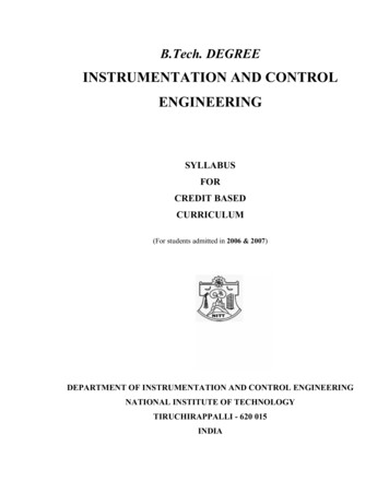
RESISTANCE TEMPERATURE DETECTORS (RTDs)Temperature DetectorsRTD ConstructionThe RTD incorporates pure metalsor certain alloys that increase inresistance as temperature increasesand, conversely, decrease inresistance as temperaturedecreases. RTDs act somewhatlike an electrical transducer,converting changes in temperatureto voltage signals by themeasurement of resistance. Themetals that are best suited for useas RTD sensors are pure, ofuniform quality, stable within agiven range of temperature, andable to give reproducibleresistance-temperature readings.Only a few metals have theproperties necessary for use inRTD elements.Figure 1Electrical Resistance-Temperature CurvesRTD elements are normally constructed of platinum, copper, or nickel. These metals are bestsuited for RTD applications because of their linear resistance-temperature characteristics (asshown in Figure 1), their high coefficient of resistance, and their ability to withstand repeatedtemperature cycles.The coefficient of resistance is the change in resistance per degree change in temperature, usuallyexpressed as a percentage per degree of temperature. The material used must be capable of beingdrawn into fine wire so that the element can be easily constructed.IC-01Page 2Rev. 0
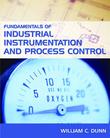
Temperature DetectorsRESISTANCE TEMPERATURE DETECTORS (RTDs)RTD elements are usually long, spring-like wires surrounded by an insulator and enclosed in asheath of metal. Figure 2 shows the internal construction of an RTD.Figure 2Internal Construction of a Typical RTDThis particular design has a platinum element that is surrounded by a porcelain insulator. Theinsulator prevents a short circuit between the wire and the metal sheath.Inconel, a nickel-iron-chromium alloy, is normally used in manufacturing the RTD sheathbecause of its inherent corrosion resistance. When placed in a liquid or gas medium, the Inconelsheath quickly reaches the temperature of the medium. The change in temperature will cause theplatinum wire to heat or cool, resulting in a proportional change in resistance.This change in resistance is then measured by a precision resistance measuring device that iscalibrated to give the proper temperature reading. This device is normally a bridge circuit, whichwill be covered in detail later in this text.Rev. 0Page 3IC-01
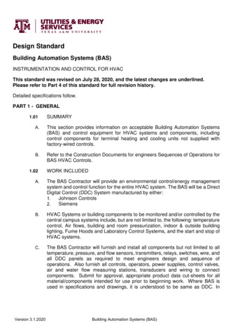
RESISTANCE TEMPERATURE DETECTORS (RTDs)Temperature DetectorsFigure 3 shows an RTD protective well and terminal head. The well protects the RTD fromdamage by the gas or liquid being measured. Protecting wells are normally made of stainlesssteel, carbon steel, Inconel, or cast iron, and they are used for temperatures up to 1100 C.Figure 3RTD Protective Well and Terminal HeadSummaryResistance temperature detectors (RTDs) are summarized below.RTD SummaryThe resistance of an RTD varies directly with temperature:-As temperature increases, resistance increases.As temperature decreases, resistance decreases.RTDs are constructed using a fine, pure, metallic, spring-like wire surrounded byan insulator and enclosed in a metal sheath.A change in temperature will cause an RTD to heat or cool, producing aproportional change in resistance. The change in resistance is measured by aprecision device that is calibrated to give the proper temperature reading.IC-01Page 4Rev. 0
Temperature DetectorsTHERMOCOUPLESTHERMOCOUPLESThe thermocouple is a device that converts thermal energy into electrical energy.EO 1.4DESCRIBE the basic construction of a thermocoupleincluding:a.Major component arrangementb.Materials usedEO 1.5EXPLAIN how a thermocouple provides an outputrepresentative of the measured temperature.Thermocouple ConstructionA thermocouple is constructed oftwo dissimilar metal wires joinedat one end. When one end of eachwire is connected to a measuringinstrument, the thermocouplebecomes a sensitive and highlyaccurate measuring device.Thermocouples may be constructedof several different combinationsof materials. The performance ofa thermocouple material isgenerally determined by using thatmaterial with platinum. The mostimportant factor to be consideredwhen selecting a pair of materialsis the "thermoelectric difference"Figure 4 Thermocouple Material Characteristicsbetween the two materials. AWhen Used with Platinumsignificant difference between thetwo materials will result in betterthermocouple performance. Figure 4 illustrates the characteristics of the more commonly usedmaterials when used with platinum.Other materials may be used in addition to those shown in Figure 4. For example: ChromelConstantan is excellent for temperatures up to 2000 F; Nickel/Nickel-Molybdenum sometimesreplaces Chromel-Alumel; and Tungsten-Rhenium is used for temperatures up to 5000 F. Somecombinations used for specialized applications are Chromel-White Gold, Molybdenum-Tungsten,Tungsten-Iridium, and Iridium/Iridium-Rhodium.Rev. 0Page 5IC-01
THERMOCOUPLESTemperature DetectorsFigure 5 shows the internal constructionof a typical thermocouple. The leads ofthe thermocouple are encased in a rigidmetal sheath. The measuring junction isnormally formed at the bottom of thethermocouple housing. Magnesium oxidesurrounds the thermocouple wires toprevent vibration that could damage thefine wires and to enhance heat transferbetween the measuring junction and themedium surrounding the thermocouple.Thermocouple OperationThermocouples will cause an electriccurrent to flow in the attached circuitwhen subjected to changes in temperature.The amount of current that will beproduced is dependent on the temperaturedifference between the measurement andreference junction; the characteristics ofthe two metals used; and thecharacteristics of the attached circuit.Figure 6 illustrates a simple thermocouple circuit.Figure 6 Simple Thermocouple CircuitIC-01Page 6Figure 5 Internal Construction of aTypical ThermocoupleHeating the measuringjunction of thethermocouple produces avoltage which is greaterthan the voltage across thereference junction. Thedifference between the twovoltages is proportional tothe difference intemperature and can bemeasured on the voltmeter(in millivolts). For ease ofope r a tor use , somevoltmeters are set up toread out directly intemperature through use ofelectronic circuity.Rev. 0
Temperature DetectorsTHERMOCOUPLESOther applications provide only the millivolt readout. In order to convert the millivolt readingto its corresponding temperature, you must refer to tables like the one shown in Figure 7. Thesetables can be obtained from the thermocouple manufacturer, and they list the specific temperaturecorresponding to a series of millivolt readings.Temperatures (oC) (IPTS 1968).oC010- 0 oelectric Voltage in Absolute 8.50418.6123040506070Reference Junction 75411.94713.15514.36815.57616.77117.9428090100- 0 4001,5001,6001,700oCFigure 7 Temperature-vs-Voltage Reference TableSummaryThermocouples are summarized below.Thermocouple SummaryA thermocouple is constructed of two dissimilar wires joined at one end andencased in a metal sheath.The other end of each wire is connected to a meter or measuring circuit.Heating the measuring junction of the thermocouple produces a voltage that isgreater than the voltage across the reference junction.The difference between the two voltages is proportional to the difference intemperature and can be measured on a voltmeter.Rev. 0Page 7IC-01
FUNCTIONAL USES OF TEMPERATURE DETECTORSTemperature DetectorsFUNCTIONAL USES OF TEMPERATURE DETECTORSTemperature sensing devices, such as RTDs and thermocouples, provide necessarytemperature indications for the safe and continued operation of the DOE facilityfluid systems. These temperature indications may include:Reactor hot and cold leg temperaturesPressurizer temperaturePurification demineralizer inlet temperatureCooling water to and from various componentsSecondary feed temperatureEO 1.6STATE the three basic functions of temperaturedetectors.EO 1.7DESCRIBE the two alternate methods of determiningtemperature when the normal temperature sensingdevices are inoperable.EO 1.8STATE the two environmental concerns which canaffect the accuracy and reliability of temperaturedetection instrumentation.Functions of Temperature DetectorsAlthough the temperatures that are monitored vary slightly depending on the details of facilitydesign, temperature detectors are used to provide three basic functions: indication, alarm, andcontrol. The temperatures monitored may normally be displayed in a central location, such asa control room, and may have audible and visual alarms associated with them when specifiedpreset limits are exceeded. These temperatures may have control functions associated with themso that equipment is started or stopped to support a given temperature condition or so that aprotective action occurs.Detector ProblemsIn the event that key temperature sensing instruments become inoperative, there are severalalternate methods that may be used. Some applications utilize installed spare temperaturedetectors or dual-element RTDs. The dual-element RTD has two sensing elements of which onlyone is normally connected. If the operating element becomes faulty, the second element may beused to provide temperature indication. If an installed spare is not utilized, a contact pyrometer(portable thermocouple) may be used to obtain temperature readings on those pieces of equipmentor systems that are accessible.IC-01Page 8Rev. 0
Temperature DetectorsFUNCTIONAL USES OF TEMPERATURE DETECTORSIf the malfunction is in the circuitry and the detector itself is still functional, it may be possibleto obtain temperatures by connecting an external bridge circuit to the detector. Resistancereadings may then be taken and a corresponding temperature obtained from the detectorcalibration curves.Environmental ConcernsAmbient temperature variations will affect the accuracy and reliability of temperature detectioninstrumentation. Variations in ambient temperature can directly affect the resistance ofcomponents in a bridge circuit and the resistance of the reference junction for a thermocouple.In addition, ambient temperature variations can affect the calibration of electric/electronicequipment. The effects of temperature variations are reduced by the design of the circuitry andby maintaining the temperature detection instrumentation in the proper environment.The presence of humidity will also affect most electrical equipment, especially electronicequipment. High humidity causes moisture to collect on the equipment. This moisture can causeshort circuits, grounds, and corrosion, which, in turn, may damage components. The effects dueto humidity are controlled by maintaining the equipment in the proper environment.SummaryDetector Uses SummaryTemperature detectors are used for: If a temperature detector becameinoperative:- A spare detector may be used(if installed)A contact pyrometer can beusedEnvironmental concerns:-Rev. 0IndicationAlarm functionsControl functionsAmbient temperatureHumidityPage 9IC-01
TEMPERATURE DETECTION CIRCUITRYTemperature DetectorsTEMPERATURE DETECTION CIRCUITRYThe bridge circuit is used whenever extremely accurate resistance measurementsare required (such as RTD measurements).EO 1.9Given a simplified schematic diagram of a basic bridgecircuit, STATE the purpose of the followingcomponents:a.R1 and R2b.Rxc.Adjustable resistord.Sensitive ammeterEO 1.10DESCRIBE the bridge circuit conditions that create abalanced bridge.EO 1.11Given a block diagram of a basic temperatureinstrument detection and control system, STATE thepurpose of the following blocks:a.RTDb.Bridge circuitc.DC-AC converterd.Amplifiere.Balancing motor/mechanical linkageEO 1.12DESCRIBE the temperature instrument indication(s) forthe following circuit faults:a.Short circuitb.Open circuitEO 1.13EXPLAIN the three methods of bridge circuitcompensation for changes in ambient temperature.Bridge Circuit ConstructionFigure 8 shows a basic bridge circuit which consists of three known resistances, R1, R2, and R3(variable), an unknown variable resistor RX (RTD), a source of voltage, and a sensitive ammeter.IC-01Page 10Rev. 0
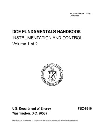
Temperature DetectorsTEMPERATURE DETECTION CIRCUITRYFigure 8 Bridge CircuitResistors R1 and R2 are the ratio arms of the bridge. They ratio the two variable resistances forcurrent flow through the ammeter. R3 is a variable resistor known as the standard arm that isadjusted to match the unknown resistor. The sensing ammeter visually displays the current thatis flowing through the bridge circuit. Analysis of the circuit shows that when R3 is adjusted sothat the ammeter reads zero current, the resistance of both arms of the bridge circuit is the same.Equation 1-1 shows the relationship of the resistance between the two arms of the bridge.R1R2R3Rx(1-1)Since the values of R1, R2, and R3 are known values, the only unkown is Rx. The value of Rxcan be calulated for the bridge during an ammeter zero current condition. Knowing thisresistance value provides a baseline point for calibration of the instrument attached to the bridgecircuit. The unknown resistance, Rx, is given by Equation 1-2.RxRev. 0R2 R3(1-2)R1Page 11IC-01
TEMPERATURE DETECTION CIRCUITRYTemperature DetectorsBridge Circuit OperationThe bridge operates by placing Rx in the circuit, as shown in Figure 8, and then adjusting R3 sothat all current flows through the arms of the bridge circuit. When this condition exists, thereis no current flow through the ammeter, and the bridge is said to be balanced. When the bridgeis balanced, the currents through each of the arms are exactly proportional. They are equal if R1 R2. Most of the time the bridge is constructed so that R1 R2. When this is the case, and thebridge is balanced, then the resistance of Rx is the same as R3, or Rx R3.When balance exists, R3 will be equal to the unknown resistance, even if the voltage source isunstable or is not accurately known. A typical Wheatstone bridge has several dials used to varythe resistance. Once the bridge is balanced, the dials can be read to find the value of R3. Bridgecircuits can be used to measure resistance to tenths or even hundredths of a percent accuracy.When used to measure temperature, some Wheatstone bridges with precision resistors areaccurate to about 0.1 F.Two types of bridge circuits (unbalanced and balanced) are utilized in resistance thermometertemperature detection circuits. The unbalanced bridge circuit (Figure 9) uses a millivoltmeter thatis calibrated in units of temperature that correspond to the RTD resistance.Figure 9IC-01Unbalanced Bridge CircuitPage 12Rev. 0
Temperature DetectorsTEMPERATURE DETECTION CIRCUITRYThe battery is connected to two opposite points of the bridge circuit. The millivoltmeter isconnected to the two remaining points. The rheostat regulates bridge current. The regulatedcurrent is divided between the branch with the fixed resistor and range resistor R1, and the branchwith the RTD and range resistor R2. As the electrical resistance of the RTD changes, the voltageat points X and Y changes. The millivoltmeter detects the change in voltage caused by unequaldivision of current in the two branches. The meter can be calibrated in units of temperaturebecause the only changing resistance value is that of the RTD.The balanced bridge circuit (Figure 10) uses a galvanometer to compare the RTD resistance withthat of a fixed resistor. The galvanometer uses a pointer that deflects on either side of zero whenthe resistance of the arms is not equal. The resistance of the slide wire is adjusted until thegalvanometer indicates zero. The value of the slide resistance is then used to determine thetemperature of the system being monitored.Figure 10Balanced Bridge CircuitA slidewire resistor is used to balance the arms of the bridge. The circuit will be in balancewhenever the value of the slidewire resistance is such that no current flows through thegalvanometer. For each temperature change, there is a new value; therefore, the slider must bemoved to a new position to balance the circuit.Rev. 0Page 13IC-01
TEMPERATURE DETECTION CIRCUITRYTemperature DetectorsTemperature Detection CircuitFigure 11 is a block diagram of a typical temperature detection circuit. This represents abalanced bridge temperature detection circuit that has been modified to eliminate thegalvanometer.Figure 11Block Diagram of a Typical Temperature Detection CircuitThe block consists of a temperature detector (RTD) that measures the temperature. The detectoris felt as resistance to the bridge network. The bridge network converts this resistance to a DCvoltage signal.An electronic instrument has been developed in which the DC voltage of the potentiometer, orthe bridge, is converted to an AC voltage. The AC voltage is then amplified to a higher (usable)voltage that is used to drive a bi-directional motor. The bi-directional motor positions the slideron the slidewire to balance the circuit resistance.If the RTD becomes open in either the unbalanced and balanced bridge circuits, the resistancewill be infinite, and the meter will indicate a very high temperature. If it becomes shorted,resistance will be zero, and the meter will indicate a very low temperature.IC-01Page 14Rev. 0
Temperature DetectorsTEMPERATURE DETECTION CIRCUITRYWhen calibrating the circuit, a precision resistor of known value is substituted for the resistancebulb, as shown in Figure 12.Figure 12 Resistance Thermometer Circuit with PrecisionResistor in Place of Resistance BulbBattery voltage is then adjusted by varying Rb until the meter indication is correct for the knownresistance.Temperature CompensationBecause of changes in ambient temperature, the resistance thermometer circuitry must becompensated. The resistors that are used in the measuring circuitry are selected so that theirresistance will remain constant over the range of temperature expected. Temperaturecompensation is also accomplished through the design of the electronic circuitry to compensatefor ambient changes in the equipment cabinet. It is also possible for the resistance of thedetector leads to change due to a change in ambient temperature. To compensate for this change,three and four wire RTD circuits are used. In this way, the same amount of lead wire is usedin both branches of the bridge circuit, and the change in resistance will be felt on both branches,negating the effects of the change in temperature.Rev. 0Page 15IC-01
TEMPERATURE DETECTION CIRCUITRYTemperature DetectorsSummaryTemperature detection circuit operation is summarized below.Circuit Operation SummaryThe basic bridge circuit consists of:-Two known resistors (R1 and R2) that are used for ratioing the adjustableand known resistancesOne known variable resistor (R3) that is used to match the unknownvariable resistorOne unknown resistor (Rx) that is used to measure temperatureA sensing ammeter that indicates the current flow through the bridgecircuitThe bridge circuit is considered balanced when the sensing ammeter reads zerocurrent.A basic temperature instrument is comprised of:-An RTD for measuring the temperatureA bridge network for converting resistance to voltageA DC to AC voltage converter to supply an amplifiable AC signal to theamplifierAn AC signal amplifier to amplify the AC signal to a usable levelA balancing motor/mechanical linkage assembly to balance the circuit’sresistanceAn open circuit in a temperature instrument is indicated by a very hightemperature. A short circuit in a temperature instrument is indicated by a verylow temperature.Temperature instrument ambient temperature compensation is accomplished by:-IC-01Measuring circuit resistor selectionElectronic circuitry designUse of three or four wire RTD circuitsPage 16Rev. 0
INSTRUMENTATION AND CONTROL Module 1 Temperature Detectors. Temperature Detectors TABLE OF CONTENTS . Industrial Instruments for Measurement and Control, Second Edition, McGraw-Hill Book Company. Process Measurement Fundamentals, Volume I, General Physics Corporation, ISBN 0-87683-001