Transcription
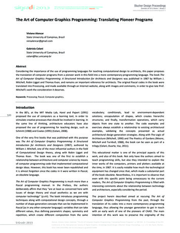
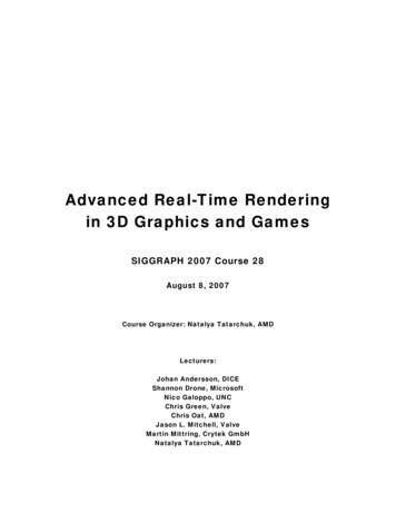
Graphics Hardware (2004)T. Akenine-Möller, M. McCool (Editors)PixelView: A View-Independent GraphicsRendering ArchitectureJ. Stewart, E.P. Bennett, and L. McMillanDepartment of Computer Science, The University of North Carolina at Chapel Hill, USAAbstractWe present a new computer graphics rendering architecture that allows “all possible views” to be extractedfrom a single traversal of a scene description. It supports a wide range of rendering primitives, including polygonal meshes, higher-order surface primitives (e.g. spheres, cylinders, and parametric patches), point-basedmodels, and image-based representations. To demonstrate our concept, we have implemented a hardware prototype that includes a 4D, z-buffered frame-buffer supporting dynamic view selection at the time of raster scan-out.As a result, our implementation supports extremely low display-update latency. The PixelView architecture alsosupports rendering of the same scene for multiple eyes, which provides immediate benefits for stereo viewingmethods like those used in today’s virtual environments, particularly when there are multiple participants. In thefuture, view-independent graphics rendering hardware will also be essential to support the multitude of viewpoints required for real-time autostereoscopic and holographic display devices.Categories and Subject Descriptors (according to ACM CCS): I.3.3 [Computer Graphics]: Viewing Algorithms;Display Algorithms; Bitmap and Frame Buffer Operations. I.3.1 [Computer Graphics]: Graphics Processors. I.3.6[Computer Graphics]: Graphics Data Structures and Data Types.1. IntroductionViewpoint specification is fundamental to traditional computer graphics rendering. Both the transformation of ascene to eye space in the traditional graphics pipeline andthe origination of viewing rays in a ray-casting system depend on the viewpoint. Moreover, many subsequent rendering steps are also impacted by the choice of viewpoint, including clipping, projection, illumination calculations,shading, and visibility determination. As a result, changingthe viewpoint frequently gates the entire process of interactive rendering, as each rendered frame is initiated with thespecification of a viewpoint, followed by the scene description, and culminating with the final displayed image.There are many potential advantages to decouplingviewpoint specification from rendering. First, immediateefficiency improvements are available if rendering costsare amortized over multiple views. They result from reuseof shading calculations as well as exploiting the coherencyof surface reflection with smooth variations in viewpoint.A second advantage results from beginning the renderingprocess before the viewing position is resolved, thereby reducing latency.However, the ultimate advantage of separating rendering from viewpoint selection is that it becomes possible torender the same scene for multiple eyes. Possible applica Eurographics Association 2004.Figure 1: Photograph of our hardware prototype of thePixelView architecture. The prototype is on the right, itsVGA output is in the middle, and the PC controller is onthe left.tions include shared virtual environments (stereo viewingby many participants of a computer-generated scene). Inthe future, view-independent graphics rendering hardwarewill also be essential to support the multitude of viewpointsrequired for real-time autostereoscopic and holographicdisplay devices.
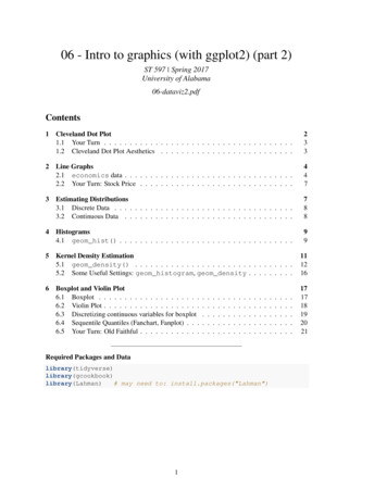
Stewart et al / PixelView: A View-Independent Graphics Rendering ArchitectureWe have developed a new computer graphics renderingarchitecture, called PixelView, in which a single traversalof the scene description generates “all possible views” (orat least a wide range of views). PixelView is compatiblewith the scene descriptions used by traditional 3D rendering hardware (i.e. polygons). In addition, PixelView, likethe Reyes rendering system and many ray-casting renderers, supports any higher-order surface primitive for which aworld-space subdivision scheme exists. It also nativelysupports point-based models as well as image-based representations, all within a unified rendering architecture.The primary contributions of our PixelView renderingsystem include: A scalable system architecture for supportingreal-time, view-independent rendering of 3-DmodelsA hardware prototype of a 4D, z-buffered framebuffer demonstrating the viability of dynamicview selection at scan-outHardware rendering of primitives with viewdependent reflectance by a technique that we call“point casting”In addition, we consider possible representations andcompressions for the radiance of view-dependent points toreduce storage and bandwidth requirements.2. OverviewWe begin with a high-level overview of PixelView via acomparison with the traditional graphics pipeline, with afocus on the role of view specification.The left side of Figure 2 shows a traditional graphicspipeline. Polygon vertices (in object space) are fed into thegeometry stage for transform and lighting. This stage outputs lit, screen-space triangles that are subsequently rasterized into fragments. These fragments are then shaded andtextured. Various other raster operations, such as depthcomparison, compositing, and filtering, can then be performed before the final color values are written into the 2Dframe buffer.The right side of Figure 2 shows the PixelView pipeline.Our system supports any primitive that can be subdividedin world space. Primitives enter the subdivision stage,where they are first transformed from object space intoworld space. The primitives then undergo world-space subdivision and are shaded and textured. The shader/texturestage outputs fully shaded world-space points, which arethen “point cast” into specific bins of the 4D frame buffer.Lastly, because a point will generally not fall exactly into abin, its contribution is “scattered” into nearby bins. Specifics of the various pipeline stages are discussed in subsequent sections. For now, we will focus on the role that viewinformation plays in each rendering approach.When comparing the pipelines, note that view specification comes into play very early in the traditional graphicspipeline. Specifically, the first operation that typically happens to vertices in the geometry stage is to transform themOpenGLGeometryPIXELVIEWView InfoSubdivisionShader/TextureRasterizationPoint CastingShader/TextureFragmentScatter2D Frame4D FrameDisplayView InfoDisplayFigure 2: High-level comparison between a typicalOpenGL-style pipeline and PixelView. Only the displaystage in PixelView requires knowledge of the viewpoint, allowing reuse of shading and rendering calculations.into eye space via the modelview matrix. Many later stepsin the pipeline are also affected by the viewpoint. Thus,changing the viewpoint requires re-traversal and rerendering of the entire scene.Alternatively, note that no view transform occurs in thePixelView geometry processing stages. In fact, no viewtransform occurs at any point along a primitive’s path intothe frame buffer. That is, no knowledge of the virtual camera’s location and orientation is required to render primitives into the 4D frame buffer. We can “get away with this”because we render a sampled version of the outgoing radiance from each point of the scene. The viewpoint specification can thus move to the display stage, where it is used toreconstruct a particular view during scan-out. This allowsthe viewpoint to change without re-rendering the scene.Furthermore, this fundamental reorganization of renderingtasks allows us to re-visit the tradeoffs between renderingquality and frequency of scene updates.3. Previous WorkThe recent advent of flexible programmable graphicshardware has ignited renewed interest in alternative architectures for real-time rendering [OKTD02; PBMH02].However, one of the least flexible remaining functions inexisting architectures is the scan-out mechanism used to refresh the display. The only exposed controls for display refresh are for setting the resolution (and perhaps setting theorigin of the memory block allocated for the frame buffer).There are compelling reasons for optimizing this functionality via a hardwired implementation. In particular, becausethe performance of graphics processing units is often dic Eurographics Association 2004.
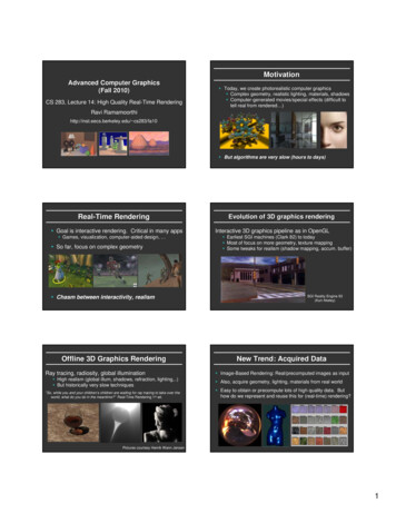
Stewart et al / PixelView: A View-Independent Graphics Rendering Architecturetated by available memory bandwidth, there is a significantbenefit in optimizing the appreciable, constant, and realtime demands of display refresh. In other words, it makessense to minimize the demands of refresh to free up memory bandwidth for other compelling rendering functions.However, the lack of flexibility in display scan-out limits the ability to address certain problems related to dynamic view selection and latency compensation [OCMB95;BFMZ94]. Regan et al. recognized this limitation and constructed a novel 3D frame buffer with flexible scan-out circuitry for the specific purpose of studying display latency[RMRK99]. Although successful at reducing latency, theirsystem lacked vertical parallax (i.e. it limited the viewingpositions to points along a specific line), and it limited theimage plane to the face of the display device. Moreover, itrequired off-line rendering to pre-compute the contents ofthe 3D frame buffer. The display stage of the PixelViewarchitecture extends and generalizes Regan et al. into a 4Dframe buffer. Its flexible scan-out stage supports both horizontal and vertical parallax. Furthermore, the PixelViewarchitecture contains geometry and rasterization stages thatallow primitives to be rendered into the 4D frame buffer.Another active area of research has been the decouplingof slow rendering processes from the interactive demandsof viewing and animation. Others have proposed specialpurpose hardware [RP94] and software [MMB97; BWG03;Gla88] rendering systems to address this problem. Many ofthese systems also incorporate 3D [RMRK99] and 4D[War98; Bal99] frame buffers or ray caches, which aresampled and interpolated to produce view-specific renderings. Most of these systems operate as lazily evaluatedcaches, meaning that samples from previously renderedviews are combined with samples from the current viewpoint. This approach generally requires no, or very little,variation in each point’s reflectance as a function of viewpoint, with the notable exception of Bala [BWG03] whomaintained a metric describing the range of views overwhich each radiance sample was valid.Our approach renders the contribution of each primitiveinto all possible views. This affords a heretoforeunexploited type of coherency that is currently unavailableto traditional view-dependent rendering architectures, at theprice of potentially rendering rays that might go unseen.There has even been some work on exploiting the coherence of rendering due to smooth variations in viewing position [Hal98]. This system effectively transformed and harnessed the power of 3D rendering to allow space-time orEPI rendering. We attempt to exploit the same sort of coherence in our shading approach. However, we do not focus on rendering epipolar planes one-at-a-time, but insteadrender the out-going radiance from each 3D point and usez-buffering to resolve visibility.Our system relies on substantial preprocessing of display primitives much like Reyes [CCC87] and Talisman[TK96]. Specifically, we are able to render directly onlythose primitives that can be appropriately subdivided inworld space. Moreover, as the average size of a renderingprimitive shrinks, alternative primitives have been sug Eurographics Association 2004.gested. Examples of these include point-based models[RL00; PZvBG00; ZPKG02; PKKG03] and image-basedmodels [SGHS98]. PixelView is capable of directly rendering and displaying point-based representations with viewdependent effects, as well as light fields [LH96] and lumigraphs [GGSC96]. Each display type can be easily combined with any of the others. Furthermore, the samplingand reconstruction strategies used in PixelView draw heavily on those developed for point-based primitives and lightfield rendering.4. The PixelView ArchitectureThis section describes the various stages in the PixelViewarchitecture. Note that this section is intended to provide ageneral, abstract description of the architecture, in contrastto the specific, concrete implementation presented in Section 5. Referring to Figure 2, we begin with the “lowerhalf” of the pipeline (i.e. rasterization and display).4.1. A 4D Frame BufferIn PixelView, the standard 2D frame buffer is replacedwith a 4D ray buffer. Frame buffers are commonly described as an array of pixels, but in the context of 3D rendering, they are more accurately characterized as an arrayof rays seen from a single viewpoint. This “frame buffer asray buffer” concept is appropriate for both ray-casting andOpenGL-style renderers.View independence is achieved by generalizing the 2D“ray buffer” into 4D. The resulting structure is, in essence,a light field/lumigraph, with rays specified by their intersection with two parallel planes [LH96; GGSC96]. Following the notation of Gortler et al. [GGSC96], we call thesetwo planes the s-t plane and the u-v plane. Our framebuffer is thus a 4D collection of radiance values, a finitesampling of light rays parameterized by (s,t,u,v). Once the4D frame buffer has been “populated”, novel views can begenerated without the need to re-render scene geometry.4.2. Display/Scan-OutNew images can be created during scan-out by taking a 2Dslice of the 4D frame buffer. This involves mapping scanout pixel coordinates (i,j) into ray coordinates (s,t,u,v).Conceptually, the pixel coordinates are specified by rays,and the intersection of these rays with the s-t plane and u-vplane defines an (s,t,u,v) quadruple, as shown in Figure 3.The resulting mapping is given by the following four linearrational equations (a derivation is given in Appendix A).s (i, j ) As i B s j C sAw i B w j C w(1)t (i, j ) At i Bt j C tAw i B w j C w( 2)u (i, j ) Au i Bu j C uAw i B w j C w(3)v(i, j ) Av i B v j C vAw i B w j C w( 4)The A, B, and C coefficients are defined with respect tothe current position and orientation of the virtual camera(i.e. the current view). Each equation has a numerator of
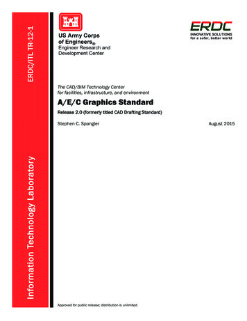
Stewart et al / PixelView: A View-Independent Graphics Rendering Architecturethe same form, though the coefficients are different. Thedenominator is identical for all four equations.These four equations represent the 2D planar slice of the4D frame buffer, which maps an (i,j) pixel coordinate to an(s,t,u,v) ray index. As the scan-out iterates through i and j,these equations generate addresses into the 4D data structure. Note that the denominator varies with i and j, requiring per-pixel division. If, however, the image plane of thevirtual camera is restricted such that it is always parallel tothe s-t and u-v parameterization, the equations simplify tothe following linear expressions.world-spacesceneufss(i, j ) As′ i B s′ j C s′(5)t (i, j ) At′i Bt′ j C t′(6)u (i, j ) Au′ i Bu′ j C u′(7)v(i, j ) Av′ i Bv′ j C v′(8)Thus, we now have simple linear expressions in terms ofpixel coordinates (i,j). Such expressions map well to hardware. The sacrifice for this elegance is that the orientationof our camera’s image plane is now restricted. However,for applications such as autostereoscopic and CAVE-stylevirtual reality displays, it is practical to define the fixedviewing surface to be parallel to the s-t and u-v planes.That is, for these applications, this viewing configuration isinherent.Our scan-out equations are similar to those used byRegan et al. in [RMRK99], but they are slightly more general. By limiting the viewing positions to points along aspecific line, and by limiting the image plane to the face ofthe display device, Equations 5, 7, and 8 can be furthersimplified to those used in [RMRK99] (Equation 6 becomes unnecessary).4.3. Point Casting and ScatterGiven a 4D frame buffer and the equations for scan-out, wemust next tackle the issue of how to fill the frame buffer.The defining characteristic that separates the PixelView architecture from being “just a light-field viewer” is its ability to render geometric primitives into its 4D frame buffer.The geometry processing stage (i.e. subdivision andshader/texture) produces world-space points, each with anassociated radiance map. These maps represent a sampledversion of the outgoing radiance for each point. This radiance needs to be added to the 4D frame buffer for each s-tsample location. This process is dubbed “point casting” toindicate that a single point broadcasts its radiance out to aset of s-t sample points, instead of the more typical mapping to just a single camera’s center of projection.As shown is Figure 4, the process is performed by firstiterating over the set of all s-t sample locations and findingthe ray connecting the current sample location with thepoint primitive. This ray is then intersected with the u-vplane, and the 2D coordinate of that intersection determinesthe u-v sample location. This represents the (s,t,u,v) location in the 4D frame buffer where the radiance will bestored if it passes the 4D z-buffer test at that location. Thevirtual cameraFigure 3: 2D depiction of rays displayed in scan-out. Eachframe, PixelView evaluates a linear expression based onthe camera matrix to determine which (s,t,u,v) rays areseen.intersection is given by the following two equations (a derivation is given in Appendix B).u ( s) Au′′s Bu′′ (9)v(t ) Av′′t Bv′′ (10)Thus, we must once again evaluate a linear expression,similar to the calculations required during scan-out. In thiscase, the coefficients are related to the (x,y,z) location ofthe scene point, the location of the u-v plane (f ), and theterms in the matrices of Equation 16 (see Appendix B).Note that, in general, the u-v intersection will not be aninteger value. That is, the ray will usually not fall exactlyin an (s,t,u,v) bin. Thus, the radiance contribution shouldbe “scattered” into nearby bins.4.4. SubdivisionPoint primitives are ideal for the PixelView architecturebecause they specify a distinct ray to each s-t and u-v sample point, simplifying the point-casting process. However,it is possible to convert other primitives into this pointbased representation through world-space subdivision.Note that all subdivision occurs without considering occlusion, which is handled through z-buffering at the time ofpoint casting.Polygonal models are subdivided into points until a sufficient density is achieved so that holes are not createdwhen the points are mapped into the 4D frame buffer. Thefirst pass of subdivision converts each polygon into a set oftriangles to simplify subdivision. Subsequent passes perform a standard midpoint subdivision algorithm. The process continues until the length of each side of the triangle isless than half the size of a sample in the 4D frame buffer.This stopping criterion is not applied to the region as awhole, but instead to each individual subdivided triangle toallow for more precise sampling on large polygons. The Eurographics Association 2004.
Stewart et al / PixelView: A View-Independent Graphics Rendering Architecturemethod is similar to the Reyes approach [CCC87], butwithout explicit advance knowledge of the camera location,requiring uniform world-space subdivision.Higher-order surfaces use subdivision algorithms morespecific to their natural parameterizations. Thus, each ofthe supported higher-order surfaces is implemented with itsown world-space subdivision procedure. For instance, asphere is subdivided by algorithmically distributing pointsover the sphere’s surface. By avoiding a traditional triangulation stage, the creation of geometry artifacts is avoided.Finding improved subdivision methods for primitives thatare more complex remains an area for future research.4.5. ShadingFor point geometry fed directly into the hardware, PixelView needs color-shading information for each surfacepoint’s (x,y,z) coordinate. For polygonal and higher-orderobjects computed by PixelView, illumination must be applied.Current rendering architectures depend on high-speedparallelism to accomplish the shading operations requiredat each point. However, the speed of a shading model is notas important when scan-out is decoupled from rendering/shading, as it is in PixelView. In order to create the illusion of smooth camera motion, traditional hardware mustre-render an entire scene into a double buffer and thenswap it at the next vertical refresh. This fill rate into thedouble buffer determines the frame rate of the system. Because PixelView can create user camera motion without resorting to reshading the entire scene, its frame rate is determined by the speed of the scan-out hardware, which is aconstant independent of scene complexity. While the useris moving the view within a scene, a new scene is beingshaded and is swapped in when complete. This independence allows implementation of more complex local andglobal shading algorithms with less concern for completinga frame by an arbitrary deadline, while still providing guaranteed view-update latency.Hardware shading might be implemented using pointsoutput from subdivision and the normals generated duringthat process. For global illumination, this would imply a retained-mode graphics interface for primitive specification,or an immediate-mode interface for local illumination.PixelView has the ability to interface with software renderers and offline storage of 4D frame buffers (e.g. 3Dmovies). This data could be loaded directly into the 4Dframe buffer, bypassing PixelView’s shading stage in amanner similar to how image-based rendering models areloaded. Another option is to transmit raw points and precomputed view-dependent global illumination, and thenlets PixelView handle the placement of those points intothe 4D frame buffer.4.6. View-Dependency of PixelsThe ability to generate a 4D frame buffer without knowingthe location of the user’s camera in advance introduces the Eurographics Association 2004.(x,y,z)world-spacesceneufssample pointsFigure 4: 2D depiction of a world-space point beingrasterized into the 4D frame buffer via “point casting”.The world-space point is tested against each s-t samplepoint to determine where u-v intersections occur. Thepoint’s radiance is then applied to those (s,t,u,v) samples.problem of accounting for scene elements with viewdependent specular reflections. Obviously, if all objects inthe scene are diffuse, this is not an issue. If there is specular data, a method for shading, formatting, and point casting this extra information is needed.The mapping of each outgoing view direction to the s-tsample points will be referred to as the radiance map of apoint. For example, Phong radiance maps tend to be simpler than ray-traced reflective maps, which can resemblepoint-specific environment maps.Dealing with point-specific radiance maps raises the issue of computing large numbers of samples for each pointand transmitting them to the hardware. Luckily, a greatdeal of exploitable coherence exists in the raw maps[LH96]. There is much more radiance-map coherence fortrue object points than for arbitrary points in space. Thiscoherence allows radiance maps to be transferred to andwithin the PixelView hardware as compressed data. For reflection and refraction, the data is not as structured, but incases with a limited viewable range, the variation in illumination is far smaller than that found, for example, in aspherical environment map. This data could still be compressed using a more typical compression algorithm, because it exhibits the same type of spatial coherence seenwhen viewing the world through a normal camera.The general structure of point-specific radiance-map coherence implies that wavelet-based compression would bea natural fit. However, there exists the opportunity to createcompression algorithms and basis functions that are bettersuited to a specific shading model, such as for specularhighlights.The point-casting process is similar for both diffuse andspecular points. PixelView acknowledges the differencebetween diffuse and specular points by requiring only asingle color for a diffuse point and a full radiance map forall s-t samples for a specular point.
Stewart et al / PixelView: A View-Independent Graphics Rendering Architecture5. A PixelView ImplementationIn order to demonstrate the feasibility and advantages ofthe PixelView architecture, we have chosen to implement aproof-of-concept prototype (see Figure 1), with the following objectives: To examine the feasibility of dynamic view selection at the time of pixel scan-outTo measure the memory bandwidth utilization ofdynamic view selection and investigate the impact of different memory organizations on the required bandwidth To investigate the addressing, coherency, andfill-rate implications of illuminating and shadingeach primitive from multiple viewing directions To explore the algorithm simplifications andtradeoffs implied by a practical hardware implementationSome of these objectives could have been addressed entirely in simulation. However, modern system design toolsmake it quite easy to move rapidly from a functional simulation model to a FPGA prototype. Moreover, the advantages of physical prototypes are that they do not wallpaperover many of the engineering issues that can be easilyoverlooked in simulation, such as accurate memory models, signal distribution, routing delays, floor planning, anddatapath complexity.Another possible implementation avenue for the PixelView architecture would be to map it onto one of today’sGraphics Processing Units (GPUs). It is clear that the trendin graphics hardware is towards increasing flexibility andgenerality. In effect, GPUs can be viewed as programmableparallel-processing units. We expect this to become increasingly true in the future. However, there are many aspects of GPUs that, at present, are rendering architecturespecific or unexposed. Examples of this include framebuffer scan-out logic and memory organization, both ofwhich are critical to demonstrating the feasibility of PixelView.We have chosen to prototype only a limited subset ofthe PixelView architecture. Specifically, our system implements only one “light slab” [LH96] of an all-views architecture. A complete all-views implementation would include at least 4 (and more likely 6) slabs to enclose a region of empty space. More slabs would be necessary inscenes with intervening occluders. Of course, there aretradeoffs between the range of actual view-independenceand the frequency of re-rendering, and we plan to investigate those tradeoffs more in the future. Even so, a singlelight-slab implementation is still technically interesting,because it maps directly to a through-the-window viewingparadigm. Thus, it would be able to support interactionssimilar to those of a single-wall CAVE VR architecture,but with support for correct stereo viewing for multipleparticipants.USB 1.1PCFPGA @ 100 MHzPCInterfaceDisplayVideoDACPoint CasterSubdivisionShader/TextureSDRAM Controller8Mx16 SDRAM @ 100MHzHolds 4D Frame Buffer and ZFigure 5: Block diagram of the PixelView prototype. Pointcasting and display occur independently, allowing scan-outrate to be decoupled from rendering rate. A host PC implements the subdivision and shader/texture stages.Lastly, we have also chosen to use a general-purposehost processor to emulate the geometry processing stagesof the PixelView pipeline. These stages generally requirefloating point computation and involve more decisionmaking and variations in control flow than the later stagesof the PixelView pipeline. We intend to investigate ahardware version of this front-end geometry processing inthe future.5.1. Hardware PrototypeThe hardware begins with the point-casting stage. Recallthat the shader/texture stage outputs world-space (x,y,z)points along with their associated radiance maps that capture view-dependent reflectance. The hardware “rasterizes”these points into the 4D frame buffer. Visibility is determined via a corresponding 4D z-buffer. Scan-out is an independent function that uses view updates from the hostPC to determine the latest view parameters at the start ofeach frame. This section gives details about how this hardware is implemented.Figure 5 features a block diagram of the hardware system. The primary components are a single XilinxXC2S300E Field Programmable Gate Array (FPGA), asingle 8Mx16 SDRAM, a 10-bit video DAC, and a USB1.1 port. The Xilinx and the SDRAM are both clocked at100 MHz. The 4D frame buffer and 4D z-buffer reside inthe SDRAM, each occupying 4Mx16. The frame buffercontains 16-bit RGB565 color values, and the z-buffer contains 16-bit two’s complement depth values. Since we arelimited to 4Mx16, the 4D buffers are organized as 8x8 s-tsample points, each with a corresponding set of 256x256 uv samples.We will first focus on point casting. The point caster receives (x,y,z,color) information from the PC. It uses this information to iterate over the s-t sample points and calculatethe corresponding u-v bins. Each s-t sample point generatesa conditional write to update the 4D frame buffer at theclosest u-v sample. However, the write occurs only if the zvalue of the current point is “nearer” than the value cur Eurographics Association 2004.
Stewart et al / PixelView: A View-Independent Graphics Rendering Architecturerently at the corresponding location in the 4D z-buffer.Given enough (x,y,z) points, the 4D frame buffer will be“fully populated” and appear as a solid image.Recall from Section 4.3 that determining u and v is arelatively straightforward evaluation of a linear expression.Specifically, it is an incremental calculation that utilizesaccumulators. No multiplication or division is necessary.Turning now to the scan-out/display hardware, it r
pens to vertices in the geometry stage is to transform them into eye space via the modelview matrix. Many later steps . cus on rendering epipolar planes one-at-a-time, but instead render the out-going radiance from