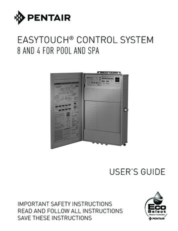
Transcription
EASYTOUCH and INTELLITOUCH CONTROL SYSTEM FOR POOL AND SPA(WITH OPTIONAL INTELLICHLOR SALT CHLORINE GENERATOR)LOAD CENTER INSTALLATION GUIDEIMPORTANT SAFETY INSTRUCTIONSREAD AND FOLLOW ALL INSTRUCTIONSSAVE THESE INSTRUCTIONS
Custoomer SupportContact Customer Support at:(800) 831-7133 - (8 A.M. to 7:30 P.M.)Sanford, North CarolinaFax: (919) 566-8920Moorpark, CaliforniaFax: (805) 553-5515Web sitesvisit www.pentairpool.com and staritepool.comP/N 521139 Rev. B 5/2016
iContentsIMPORTANT WARNING AND SAFETY INSTRUCTIONS. iiiGeneral Installation Information.vSection 1: Pentair Water Pool and Spa Control System Load Center and Power Center Overview. 1Load Center and Power Center Installation Overview. 2Load Center with subpanel (EasyTouch and IntelliTouch Systems). 3Power Center (without built-in Subpanel) - IntelliTouch System Only. 4Preparing the Load Center and Power Center Enclosure. 5Mounting the Load Center and Power Center. 6Connecting AC Power to the Load Center and Power Center. 7Electrical Wiring High Voltage Connections. 8Installing Conduit and Wire to the Enclosure. 8Accessing the EasyTouch or IntelliTouch Circuit Board and Electronics. 10Connecting the EasyTouch System Relays. 11Connecting the IntelliTouch System Relays. 12Installing Valve Actuators. 13Adjusting the valve position. 13Installing and Connecting Temperature Sensors. 15Water Temperature Sensor. 15Ambient Air Temperature Sensor (for freeze protection). 15Solar Temperature Sensor (Optional). 16Connecting a Standard Gas Heater (EasyTouch and IntelliTouch System). 17Wiring Pentair UltraTemp Heat Pump. 18Wiring Pentair IntelliFlo Pumps. 18Connecting IntelliChlor (SCG) Power Cord to the Enclosure . 20Connecting IntelliChlor (SCG) COM Port Cable . 21Wiring a Salt Chlorine Generator. 23Wiring IntelliChlor . 23Wiring IntelliChlor (SCG) Transformer to a Filter Pump. 24Rewiring the IntelliChlor SCG Transformer for 120VAC. 26Rewiring the System Transformer for 240 VAC. 27Section 2: EasyTouch System Overview. 28EasyTouch 8 and 4 Pool and Spa Control System Kit Contents. 28EasyTouch Accessory Equipment. 28EasyTouch Model Part Numbers. 29EasyTouch System Start-Up. 30EasyTouch Circuit Board Connections. 31EasyTouch System Wiring Diagram . 32EasyTouch , IntelliTouch Control System Load Center Installation Guide
iiContents (continued)Section 3: IntelliTouch System Overview. 33IntelliTouch System Components. 33Load Center or Power Center. 33IntelliTouch Personality Kits. 33IntelliTouch Accessory Power Center Expansion Kits. 34IntelliTouch Personality Kit Contents. 34Optional Equipment (IntelliChem). 34Optional IntelliTouch Expansion Enclosure. 36Kit Contents. 36Affixing the System Wiring Diagram Label. 36System Start-Up. 37Check Electronics. 37System Test. 37Testing the auxiliary relays. 37Solar System Installation. 38Solar System Start-Up. 38Pool Cleaner Protection. 38Installing the IntelliTouch Control Panel. 39IntelliTouch Outdoor Control Panels . 40IntelliTouch System Wiring Diagrams. 41Plumbing Requirements. 44Equipment Location. 45Glossary. 47EasyTouch , IntelliTouch Control System Load Center Installation Guide
iiiIMPORTANT WARNING AND SAFETY INSTRUCTIONSREAD AND FOLLOW ALL WARNING AND SAFETY INSTRUCTIONSSERIOUS BODILY INJURY OR DEATH CAN RESULT IF THIS PRODUCT (UNIT) IS NOTINSTALLED AND USED CORRECTLY.INSTALLERS, POOL OPERATORS AND POOL OWNERS MUST READ THESEWARNINGS AND ALL INSTRUCTIONS BEFORE USING THIS PRODUCT. This Guideprovides installation and operation instructions for the product. Consult PentairWater Pool and Spa, Inc. (“Pentair”) with any questions regarding thisproduct.This product is intended for use in swimming pool applications only.Most states and local codes regulate the construction, installation, and operation of public pools and spas, and the construction of residential pools and spas. It is important tocomply with these codes, many of which directly regulate the installation and use of thisproduct. Consult your local building and health codes for more information.IMPORTANT NOTICE - Attention Installer: This Installation Guide (“Guide”) containsimportant information about the installation, operation and safe use of this product. ThisGuide should be given to the owner and/or operator of this equipment.Attention User: This Guide contains important information that will help you in operating and maintainingthis product. Please retain it for future reference.Before installing this product, read and follow all safety warning notices and instructions which are included.Failure to follow safety warnings and instructions can result in severe injury, death, or property damage. Call(800) 831-7133 for additional free copies of these instructions.This product is designed and manufactured for safe and reliable service when installed, operatedand maintained according to the information and installation codes referred to in this Guide.This is a safety alert symbol. When you see this symbol in this manual or on the product, lookfor one of the following signal words; DANGER, WARNING, CAUTION and NOTICE and complywith the information. Be alert to the potential hazard. Ensure to read and comply with all of the warnings andcautions in this manual.Risk of Electrical Shock or Electrocution!- Always disconnect power at the circuit breaker before servicing the load center- Improper installation can create an electrical shock hazard that can result in death or seriousinjury.This product must be installed by a licensed or certified electrician or a qualifiedpool professional in accordance with the current National Electrical Code (NEC),NFPA 70 or the Canadian Electrical Code (CEC), CSA C22.1. All applicablelocal installation codes and ordinances must also be adhered to. Improperinstallation will create an electrical hazard which could result in death or seriousinjury to pool users, installers or others due to electrical shock, and may alsocause damage to property. Always disconnect the power to the pool light at thecircuit breaker before servicing the light. Failure to do so could result in death orserious injury to serviceman, pool users or others due to electrical shock.EasyTouch , IntelliTouch Control System Load Center Installation Guide
ivIMPORTANT WARNING AND SAFETY INSTRUCTIONSWater temperature in excess of 100 F (37.7 C) may be hazardous to your health.Prolonged immersion in hot water may induce hyperthermia. Hyperthermia occurswhen the internal temperature of the body reaches a level several degrees abovenormal body temperature of 98.6 F (37 C.). Effects of hyperthermia include:(1) Unawareness of impending danger. (2) Failure to perceive heat. (3) Failure torecognize the need to leave the spa. (4) Physical inability to exit the spa. (5) Fetaldamage in pregnant women. (6) Unconsciousness resulting in danger of drowning.The use of alcohol, drugs, or medication can greatly increase the risk of fatalhyperthermia in hot tubs and spas.A pool or spa pump must be installed by a qualified pool and spa service professionalin accordance with the current National Electrical Code and all applicable local codesand ordinances. Improper installation may create an electrical hazard which couldresult in death or serious injury to pool users, installers, or others due to electricalshock, and may also cause damage to property.The use of alcohol, drugs, or medication can greatly increase the risk of fatal hyperthermiain hot tubs and spas. This product is intended to control heaters with built-in high limitcircuits ONLY. Failure to do so may cause property damage or personal injury.Do not use this product to control an automatic pool cover. Swimmers may becomeentrapped underneath the cover.For units intended for use in other than single-family dwellings, a clearly labeledemergency switch shall be provided as part of the installation. The switch shall be readilyaccessible to the occupants and shall be installed at least five (5) feet (1.52 m) away,adjacent to, and within sight of, the unit.Except for listed spa-side remote controls, install a minimum of five (5) feet (1.52 m) fromthe inside wall of the pool and spa.The electrical supply for this product must include a suitably rated switch or circuitbreaker to open all ungrounded supply conductors to comply with the current NationalElectrical Code (NEC), NFPA 70 or the Canadian Electrical Code (CEC), CSA C22.1.All applicable local installation codes and ordinances must also be adhered to. Thedisconnecting means must be readily accessible to the tub occupant but installed at leastfive 5ft. (1.52 m), (Canada 3 m (9.75 ft) from the inside wall of the pool.Use only copper supply conductor’s rated for 60C/75C sized based on ampacity tosupport all loads (refer to NEC tables). Load center input supply to be protected by150 Amp Maximum, 240 VAC Main Circuit Breaker.For information about the Virginia Graeme Baker Pool and Spa Safety Act, contact the Consumer Product SafetyCommission at (301) 504-7908 or visit www.cpsc.gov.NOTE: Always turn off all power to the pool pump before installing the cover or working on any suction outlet.Two Speed Pump Controls Notice (Title 20 Compliance)Please read the following important Safety Instructions - When using two-speed pumpsmanufactured on or after January 1, 2008, the pump’s default circulation speed MUST be set to theLOWEST SPEED, with a high speed override capability being for a temporary period not to exceedone normal cycle, or two hours, whichever is less.EasyTouch , IntelliTouch Control System Load Center Installation Guide
vIMPORTANT WARNING AND SAFETY INSTRUCTIONSFCC Standard - 47 CFR Part 15, Subpart C (Section 15.247). This version is limited to chapter 1to chapter 11 by specified firmware controlled in the U.S.A.Canada - Industry Canada (IC) - The IntelliChlor device complies with RSS210 of IndustryCanada. (1999). Operation is subject to the following two conditions: (1) this device may not causeinterference, and (2) this device must accept any interference, including interference that may causeundesired operation of the device.Instruction to user - The IntelliChlor device has been tested and found to comply with the limitsfor a Class B digital device, pursuant to Part 15 of the FCC Rules. These limits are designedto provide reasonable protection against harmful interference in a residential installation. TheIntelliChlor device generates, uses and can radiate radio frequency energy and, if not installed andused in accordance with the instructions, may cause harmful interference to radio communications.However, there is no guarantee that interference will not occur in a particular installation. If thisdevice does cause harmful interference to radio or television reception, which can be determined byswitching the device off and on, the user is encouraged to try to correct the interference by one ormore of the following measures: Reorient or relocate the receiving antenna.Increase the separation between the equipment and receiver.Connect the equipment into an outlet on a circuit different from that to which the receiver isconnected.Consult the dealer or an experienced radio/TV technician for help.Note: The user is cautioned that changes and modifications made to the IntelliChlor SCG devicewithout the approval of the manufacturer could void the user’s authority to operate this equipment.General Installation Information1. All work must be performed by a licensed electrician, and must conform to all national, state, andlocal codes.2. Install to provide drainage of compartment for electrical components.3. If this system is used to control underwater lighting fixtures, a ground-fault interrupter (GFCI) mustbe provided for these fixtures. Conductors on the load side of the ground-fault circuit-interruptershall not occupy conduit, junction boxes or enclosures containing other conductors unless suchconductors are also protected by a ground-fault circuit-interrupter. Refer to local codes for details.4. A terminal bar stampedis located inside the supply terminal box. To reduce the risk of electricshock, this terminal must be connected to the grounding means provided in the electric supplyservice panel with a continuous copper wire equivalent in size to the circuit conductors supplyingthis equipment (no smaller than 12 AWG or 3.3 mm). The bonding lug(s) provided on this unitare intended to connect a minimum of one No. 8 AWG for US installation and two No. 6 AWG forCanadian installations solid copper conductor between this unit and any metal equipment, metalenclosures or electrical equipment, metal water pipe, or conduit within 5 feet (1.5 m) of the unit.5. The electrical supply for this product must include a suitably rated switch or circuit breaker to openall ungrounded supply conductors to comply with in accordance with the current National ElectricalCode (NEC), NFPA 70 or the Canadian Electrical Code (CEC), CSA C22.1. All applicable localinstallation codes and ordinances must also be adhered to. The disconnecting means must bereadily accessible to the tub occupant but installed at least 10 ft. (3.05 m) from the inside wall ofthe pool.6. GAS HEATER: This automation control system is designed to supply high voltage (120 VAC / 240VAC) to a gas heater and override the thermostat in the heater’s control circuit. This automationcontrol system is intended to control gas heaters with a high temperature limit switch(s) safetycircuit.EasyTouch , IntelliTouch Control System Load Center Installation Guide
viPentair Water Pool and Spa IMPORTANT SAFETY INSTRUCTIONSFor Installation of Electrical Controls at Equipment Pad(ON/OFF Switches, Timers and Automation Power Center)Install all electrical controls at equipment pad, such as on/off switches, timers, andcontrol systems, etc. to allow the operation (start-up, shut-down, or servicing) of anypump or filter so the user does not place any portion of his/her body over or near thepump strainer lid, filter lid or valve closures. This installation should allow the userenough space to stand clear of the filter and pump during system start-up, shut downor servicing of the system filter.CAUTION! INSTALL POWER CENTER TO ALLOW USER ENOUGH SPACE TO STANDCLEAR OF PUMP AND FILTER WHEN SERVICING.HAZARDOUS PRESSURE: STAND CLEAR OF PUMP AND FILTER DURING START-UPEasyTouch , IntelliTouch Control System Load Center Installation Guide
1Section 1 EasyTouch and IntelliTouch Control SystemLoad Center and Power Center OverviewLoad Center and Power Center DescriptionLoad Center with sub-panel (EasyTouch and IntelliTouch Control System): A Load Centerenclosure provides a built-in a 120 VAC/240 VAC 150 AMP circuit breaker base (sub-panel) for highvoltage power relays, transformer, and low voltage circuit breakers. A Load Center can be factoryconfigured for an EasyTouch Control System (8 or 4 auxiliary relays) or IntelliTouch Control System(for Personality Interface Kits, see page 33) automation control system. The optional IntelliChlor SaltChlorine Generator (SCG) transformer is available in the Load Center enclosure. The Load Centerdimensions are 26” H x 17” W x 5¼” D.EasyTouch / IntelliTouch Control SystemLoad CenterNote. For EasyTouch and IntelliTouch ControlSystem product information, see the PentairProduct Catalog.Power Center without sub-panel (IntelliTouch Control System only): A Power Center enclosuredoes not include a built-in circuit breaker base (subpanel). An IntelliTouch control systemautomation control system Power Center is factory configured (depending on the IntelliTouch controlsystem Personality interface kit. Multiple Power Centers can be connected together for additionalhigh voltage relay and transformer requirements. The optional IntelliChlor Salt Chlorine Generator(SCG) transformer is available in the Power Center enclosure. The Power Center dimensions are 20”H x 17” W x 5¼” D.Note: For IntelliTouch systems (see page 33), up to three additional Power Centers (with ExpansionCenter Personality kit, i5x or i10x) can be connected to a base IntelliTouch Load Center or PowerCenter (models i5 3, i5 3S, i7 3, i9 3, i9 3S, i10 3D. For more information about using multipleexpansion centers, refer to the IntelliTouch Systems User’s Guide (P/N 521075).Main IntelliTouchControl SystemLoad Center(i5 3, i5 3S, i7 3,i9 3, i9 3S, i10 3D)Power Center(i5x or i10x),AdditionalExpansionCenterAdditionalExpansion Center(3 maximum)(P/N 521214 withIntelliChlor SCGtransformer)(P/N 521216 withoutIntelliChlor SCGtransformer)EasyTouch , IntelliTouch Control System Load Center Installation Guide
2Load Center and Power Center Installation OverviewRISK OF ELECTRICAL SHOCK. BEFORE REMOVING THE HIGH VOLTAGE COVER PANELFROM THE ENCLOSURE switch the main power OFF into the home at the main circuit breaker box.Before installing the Load Center or Power Center read the following guidelines carefully: The Load Center and Power Center must be installed at the equipment pad.AC power for the Load Center or Power Center must be provided from the main circuitbreaker panel located at the house.All electrical equipment, except for UL Listed spa-side remote switches, must be installedno less than five (5) feet (1.5 m), (Canada, 3 mm (9.75 ft) from pool and/or spa, andcomply with all national, state, and local codes (UL Listed spa-side remote switches may beinstalled at near waterline).Install the Load Center or Power Center no less than five (5) feet (1.5 m) from pool, spa,and hot tub. Additionally, the installation shall allow the user enough space to stand clearof the filter and pump during system start-up, as explained on page vi.The TYPE 3R “Rainproof” enclosure can be mounted outside or inside of a pool equipmentshed or other enclosure.Before choosing the final location for the enclosure, consider the length of all of theconductors that will have be connected to the enclosure. Make sure to consider cablelengths for the sensors to the load center location. The air temperature sensor cable isthree (3) feet (91.44 cm) long and the water temperature sensor cable is 25 feet (7.62 m)long.Mount the load center on a flat vertical surface so the conduit knockouts are located at thebottom of the enclosure. Upper and lower brackets are provided to mount the enclosure.DO NOT mount the enclosure horizontally. Water can enter the conduit knockouts andcause damage to the system and an electrical shock hazard. Install with conduit knockoutsdown.Consider the load center location when routing conduit carrying the AC power to the loadcenter, and the conduit that will be run to the high voltage equipment.Install the load center so that drainage is provided for all electrical components.Motors should be listed for pool and spa applications and have built-in thermal protection.Allow at least 5 ft (1.5 m) of unobstructed access to the front of the load center for theowner or service personnel.The load center provides grounding screw terminals for grounding all equipment. Allequipment including the load center enclosure must be bonded to earth ground.EasyTouch , IntelliTouch Control System Load Center Installation Guide
3Load Center (with built-in Subpanel) EasyTouch and IntelliTouch Control SystemsThe Load Center must be installed at the equipment pad. The AC power for the Load Center is providedfrom the main-panel circuit breaker located at the house.EasyTouch or IntelliTouch ControlSystem ControlPanel (EasyTouch(shown)Control Panel / Low voltage compartment3 AMP Low voltage(12 VAC, 18 VAC,24 VAC) systemcircuit breakersOptional 12 AMPLow voltage (24VAC) circuit breaker(IntelliChlor SaltChlorine Generator)Auxiliary,(1-4) relay locationswith additional five(5 ) relays or2-Speed Pumprelay (optional)Door SpringlatchCircuit breakerbase 150 AMP(Subpanel)Low voltageraceway(Air and watertemperaturesensors, motorized valves,indoor controlpanel, spa sideremote, andwirelessantenna)Optional IntelliChlor (SCG)cell connector socketSystem transformer:120VAC, 2.5A,240VAC, 1.3A,50/60 HzGround buss barAC PowerConnectorTransformer foraltS ChlorineGenerator(SCG)OptionOptional IntelliChlorSalt ChlorineGenerator (SCG)and power supply transformer(SCG system only).120VAC, 2A, 240VAC,1A, 50/60 HzGFCI/GFCBknockout (approvedrainproof coverrequired) - StandardSingle gang box.Enclosure conduit knockouts(see page 7): 1¼”, 1”, ¾” and½” conduit knockouts (lowerand rear) for high voltageoutput. 1” conduitknockout (lower) for highvoltage inputEasyTouch or IntelliTouch Control System Load Center(26” H x 17” W x 5¼” D)Bonding lugs (two each)No.8 AWG (US) or No.6 AWG (Canada)Load centerfront doorHigh voltagecover panelEasyTouch , IntelliTouch Control System Load Center Installation Guide
4Power Center (without built-in Subpanel) - IntelliTouch Control System OnlyThe IntelliTouch Control System Power Center (without sub-panel) must be installed at theequipment pad. AC power to the Power Center is provided from the an electrical circuit breakerpanel (sub-panel) installed at the equipment pad. The Power Center should be installed next to theControl Panel/Lowvoltage compartmentOptional Serial COM Port Expansion Board(Brackets support two boards)IntelliChlor SCG circuit board (optional)IntelliTouchControl SystemControl PanelAuxiliary,(1-5) relay locationswith additional fourrelays or2-Speed Pump relay(optional)3 AMP Low voltage Control systemcircuit breakers(12 VAC, 18 VAC,24 VAC)Optional 12 AMPcircuit breakerfor IntelliChlorSalt ChlorineGenerator(24 VAC)Low voltage raceway(Air and watertemperature sensors,motorized valves, indoorcontrol panel, spa sideremote, and wirelessantenna)Door springlatchGround buss barSystem transformer.120VAC, 2.5A,240VAC, 1.3A,50/60 HzOptional IntelliChlorSalt ChlorineGenerator powersupplytransformer(SCG system only).120VAC, 2A,240VAC, 1A,50/60 HzGFCI/GFCBknockout(approvedrainproof coverrequired)Optional IntelliChlor (SCG) cellconnector socketEnclosure conduit knockouts (see page 7): 1¼”,1”, ¾” and ½” conduitknockouts (lower andrear) for high voltageoutput. 1” conduitknockout (lower) for highvoltage inputBonding lugs (two each)No.8 AWG (US) or No.6AWG (Canada)IntelliTouch Control System Power Center (20” H x 17” W x 5¼” D)(Front view with door and high voltage cover panel removed)EasyTouch , IntelliTouch Control System Load Center Installation Guide
5Preparing the Load Center and Power Center EnclosureBEFORE INSTALLING THE LOAD CENTER AND POWER CENTER, ALWAYSSWITCH OFF THE MAIN POWER into the home at the main circuit breaker box.Before mounting the Load Center or Power Center, first remove the front door and the high voltagecover panel to access the enclosure conduit knockouts and low voltage raceway(see pages 3 and 4).To remove the Load Center or Power Center high voltage cover panel:1. Unpack the Load Center or Power Center from the shipping carton.2. Unlatch the front door spring latch and open the front door.3. Remove the two (2) retaining screws securing the high voltage cover-panel. Remove theHIGH VOLTAGE COVER PANEL from the enclosure.4. For new installation, proceed with: Mounting the Load Center and Power Center, page 6 Connecting AC Power to the Load Center and Power Center, page 7 Electrical Wiring and High Voltage Connections, page 8 Installing Conduit and Conductors to the Enclosure, page 8 Accessing the EasyTouch or IntelliTouch Control Circuit Board and Electronics, page 10 Connecting a Standard Gas Heater (EasyTouch and IntelliTouch System), page 175. After electrical connections have be completed, reinstall the high voltage panel and secureit with the two (2) retaining screws.Retaining screws(for High VoltageCover Panel)High VoltageCover PanelFront doorLoad Center (front view)EasyTouch , IntelliTouch Control System Load Center Installation Guide
6Mounting the Load Center and Power CenterMount the Load Center (EasyTouch Control System enclosure show below) and Power Center ona flat vertical surface, such as a wall or post at eye level, at least 5 ft. (1.5 m), (Canada 3 m (9.75 ft))from the pool, spa
EasyTouch , IntelliTouch Control System Load Center Installation Guide , IntelliTouch Control System Load Center Installation Guide General Installation Information 1. All work must be performed by a licensed electrician, and
