Transcription
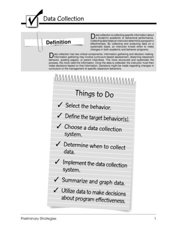
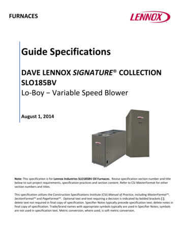
FURNACESGuide SpecificationsDAVE LENNOX SIGNATURE COLLECTIONSLO185BVLo‐Boy Variable Speed BlowerAugust 1, 2014Note: This specification is for Lennox Industries SLO185BV Oil Furnaces. Revise specification section number and titlebelow to suit project requirements, specification practices and section content. Refer to CSI MasterFormat for othersection numbers and titles.This specification utilizes the Construction Specifications Institute (CSI) Manual of Practice, including MasterFormat ,SectionFormat and PageFormat . Optional text and text requiring a decision is indicated by bolded brackets [ ];delete text not required in final copy of specification. Specifier Notes typically precede specification text; delete notes infinal copy of specification. Trade/brand names with appropriate symbols typically are used in Specifier Notes; symbolsare not used in specification text. Metric conversion, where used, is soft metric conversion.
FURNACESSECTION 23 54 00PART 1 ‐ GENERAL1.1 SECTION INCLUDEA. Oil FurnacesSpecifier Note: Revise paragraph below to suit project requirements. Add section numbers andtitles per CSI MasterFormat and specifier’s practice.1.2 RELATED SECTIONSSpecifier Note: Article below may be omitted when specifying manufacturer’s proprietary productsand recommended installation. Retain Reference Article when specifying products and installation byan industry reference standard. If retained, list standard(s) referenced in this section. Indicate issuingauthority name, acronym, standard designation and title. Establish policy for indicating edition dateof standard referenced. Conditions of the Contract or Division 1 References Section may establishthe edition date of standards. This article does not require compliance with standard, but is merely alisting of references used. Article below should list only those industry standards referenced in thissection. Retain only those reference standards to be used within the text of this Section. Add anddelete as required for specific project.1.3 REFERENCESA.B.C.D.E.F.Units are certified by AHRIU.S Department of Energy (DOE), units rated toUnits are labeled according Federal Trade Commission (FTC) requirementsUnits are ETL‐Intertek listedEnergy Star CertifiedBurners are U.L approved, C.S.A certified and certified according to ANSI Standard 296.6Specifier Note: Article below should be restricted to statements describing design or performancerequirements and functional (not dimensional) tolerances of a complete system. Limit descriptions tocomposite and operational properties required to link components of a system together and tointerface with other systems.1.4 PERFORMANCE REQUIREMENTSA. Nominal oil heat input: 79/105 79,000/105,000 btuh , 124/141 124,000/141,000 btuhB. Annual Fuel Utilization Efficiency (AFUE): 85%C. Nominal Add‐on Cooling Capacity: [3.5‐][ 5‐] tonsFURNACES2
D. Electrical Characteristics1. 60 HZ2. 120 V3. Single Phase4. 24V Transformer5. Fuel Requirements: OilSpecifier Note: Article below includes submittal of relevant data to be furnished by Contractor before,during or after construction. Coordinate this article with Architect’s and Contractor’s duties andresponsibilities in Conditions of the Contract and Division 1 Submittal Procedures Section.1.5 SUBMITTALSA. General: Submit listed submittals in accordance with Conditions of the Contract and Division1Submittal ProceduresB. Product Data: Submit product data, including manufacturer’s SPEC‐DATA product sheet, forspecified productsC. Shop Drawings:1. Submit shop drawings in accordance with Section [01 33 00 ‐ Submittal Procedures]2. Indicate:a. Equipment, piping and connections, together with valves, strainers, controlassemblies, thermostatic controls, auxiliaries and hardware and recommendedancillaries which are mounted, wired and piped ready for final connection tobuilding system, its size and recommended bypass connections.b. Piping, valves and fittings shipped loose showing final location in assemblyc. Control equipment shipped loose, showing final location in assemblyd. Field wiring diagramse. Dimensions, internal and external construction details, installation clearances,recommended method of installation, sizes and location of mounting bolt holesf. Detailed composite wiring diagrams for control systems showing factoryinstalled wiring and equipment on packaged equipment or required forcontrolling devices or ancillaries, accessories, controllers.D. Quality Assurance:1. Test Reports: Certified test reports showing compliance with specified performancecharacteristics and physical properties2. Certificates: Product certificates signed by manufacturer certifying materials complywith specified performance characteristics and criteria and physical requirements3. Manufacturer’s Instructions: Manufacturer’s installation instructionsSpecifier Note: Coordinate paragraph below with Part 3 Field Quality Requirements Article herein.Retain or delete as applicable.E. Manufacturer’s Field Reports: Manufacturer’s field reports specified hereinFURNACES3
F. Closeout Submittals: Submit the following:1. Warranty: Warranty documents specified herein2. Operation and Maintenance Data: Operation and maintenance data for installedproducts in accordance with Division 1 Closeout Submittals (Maintenance Data andOperation Data) Section. Include methods for maintaining installed products andprecautions against cleaning materials and methods detrimental to finishes andperformance. Include names and addresses of spare part suppliers.3. Provide brief description of unit, with details of function, operation, control andcomponent service4. Commissioning Report: Submit commissioning reports, report forms and schematics inaccordance with Section [01 81 00 – Commissioning]1.6 QUALITY ASSURANCEA.Qualifications:1. Installer experienced in performing work of this section who has specialized ininstallation of work similar to that required for this project2.B.Manufacturer Qualifications: Manufacturer capable of providing field servicerepresentation during construction and approving application methodPre‐installation Meetings: Conduct pre‐installation meeting to verify project requirements,manufacturer’s installation instructions and manufacturer’s warranty requirements. Complywith Division 1 Project Management and Coordination (Project Meetings).1.7 DELIVERY, STORAGE & HANDLINGA.B.C.D.General: Comply with Division 1 Product RequirementsOrdering: Comply with manufacturer’s ordering instructions and lead time requirements toavoid construction delaysPacking, Shipping, Handling and Delivery:1. Deliver materials in manufacturer’s original, unopened, undamaged containers withidentification labels intact2. Ship, handle and unload units according to manufacturer’s instructionsStorage and Protection:1. Store materials protected from exposure to harmful weather conditions2. Factory shipping covers to remain in place until installationSpecifier Note: Coordinate article below with Conditions of the Contract and Division 1 CloseoutSubmittals (Warranty).FURNACES4
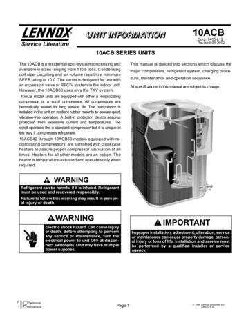
1.8 WARRANTYA.B.Project Warranty: Refer to Conditions of the Contract for project warranty provisionsManufacturer’s Warranty: Submit, for Owner’s acceptance, manufacturer’s standard warrantydocument executed by authorized company official. Manufacturer’s warranty is in addition to,and not a limitation of, other rights Owner may have under Contract DocumentsSpecifier Note: Coordinate paragraph below with manufacturer’s warranty requirements.C. Warranty: Commencing on Date of InstallationSpecifier Note: Refer to Lennox Equipment Limited Warranty certificate included with equipment fordetails.1. Heat exchanger ‐ Limited lifetime warranty in residential applications.2. Oil burners and all other covered components – 10‐year limited warranty in residentialapplications.PART 2 ‐ PRODUCTSSpecifier Note: Retain article below for proprietary method specification. Add product attributes,performance characteristics, material standards, and descriptions as applicable. Use of such phrases as“or equal” or “or approved equal” or similar phrases may cause ambiguity in specifications. Suchphrases require verification (procedural, legal and regulatory) and assignment of responsibility fordetermining “or equal” products.2.1 OIL FURNACEA.B.C.Product: Lo‐Boy Oil FurnacesManufacturer: Lennox Industries1. 1. Contact: 2140 Lake Park Blvd.; Richardson, TX 75080; Telephone: (800) 453‐6669;website: www.lennoxcommercial.comProprietary Products/Systems:1. Cabinet:a.Heavy gauge steelb.Pre‐painted textured finishc.Entire heating section is lined with foil faced fiberglass insulationd.e.f.g.h.i.FURNACESComplete service access to blowerBlower compartment is completely insulatedReturn air entry is possible on either side or bottom of cabinetRemoval of louvered heating section door allows access to oil burner,inspection door and control compartmentDoor is equipped with handhold for ease of removalControl compartment is totally enclosed to provide a safe, compact, cleanarea5
Oil line and electrical inlets openings are provided in sidesLo‐boy models have a lower profile than standard upflow oil furnaces, theyare configured with both supply and return air openings on top of unitl.Flue outlet1. Located on top of cabinet on front flue models and can be relocated toeither sides2. Rear flue models allow the flue to be installed away from indoor coilsand air cleanersHeating System:a.Beckett NX Oil Burner3. Smooth operating, high pressure atomizing type burner4. Heavy duty motor5. Air turbo injector6. Flame retention head7. All parts are removable for servicing8. Factory installed, wired and fire tested9. 120VAC primary safety control and ceramic glazed electrodes10. Nozzle provided for field conversion to higher heating capacity11. Factory installed cadmium sulfide cell flame detector and primary safetycontrolb.Advanced Burner Control1. 120VAC primary safety control2. Controls the oil burner motor and igniter3. Welded relay protection4. Limited reset and recycle5. Reset button6. 3 status lights for system monitoring and diagnosticsa. Yellow : pump prime modeb. Green: flame sensingc. Red: restricted lockout7. Valve‐On delay/ Motor‐Off Delay8. 15 second lockout time9. Interrupted or intermittent duty ignition10. Disable function11. Technician pump priming modec.EZ Clean Heat Exchanger1. Streamlined drum type heat exchanger exposes maximum surface areawith minimum air resistance2. Heavy gauge steel3. Strategically placed poles for easy cleaningj.k.2.FURNACES6
d.e.f.4.Blowera.b.c.d.5.4. Mounting channels are provided in cabinet base for supportCombustion Chamber1. Factory installed, specially designed with alumina silica ceramic fiber2. Can withstand temperatures of up to 2550 degrees FFlame Inspection Tube1. Located at the front of the unit2. Opening is large enough for normal inspection mirrorBarometric Draft Control1. Field installed in flue pipeVariable speed direct drive blowerEach blower is statically and dynamically balancedChange in blower speed is easily accomplished by simple jumper changeEasily removed for servicingFilterLarge, cleanable, frame‐type filters availableControlsa.Electronic blower control1. Single stage cooling airflow ramp up2. Two stage cooling airflow ramp up3. Passive and active dehumidification4. Continuous blower operationb.Powered air cleaner connectionsc.Transformer1.24 V/40VA transformer2.Factory installedd.Limit Control1.Factory installed on vestibule panel[Optional Accessories:]a.[Heating:]1.[Oil Filter]2.[Two‐Stage Oil Pump]3.[Air Intake Kit]a. [Provides 4in. air inlet connection to burner foroutdoor combustion air]b.[Controls:]1.[ComfortSense 7000 Touchscreen Thermostat]a.6.7.2.FURNACES[Thermostat]7
2.2 PRODUCT SUBSTITUTIONSA.Substitutions: No substitutions permitted.PART 3 ‐ EXECUTION3.1 MANUFACTURER’S INSTRUCTIONSSpecifier Note: Article below is an addition to the CSI SectionFormat and a supplement to MANU‐SPEC.Revise article below to suit project requirements and specifier’s practice.A.Compliance: Comply with manufacturer’s written data, including product technicalbulletins, product catalog installation instructions, product carton installation instructionsand [Lennox Industries] SPEC‐DATA sheets.3.2 EXAMINATIONA.Site Verification of Conditions: Verify substrate conditions, which have been previouslyinstalled under other sections, are acceptable for product installation in accordance withmanufacturer’s instructions.3.3 INSTALLATIONA. Install [Oil Furnace] in accordance with manufacturer’s instructions and regulations ofauthorities having jurisdiction.END OF SECTIONBulletin No. 000368 (August 2014)FURNACES8
August 1, 2014 FURNACES Note: This specification is for Lennox Industries SLO185BV Oil Furnaces. Revise specification section number and title below to suit project requirements, specification practices and section