Transcription
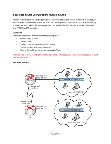
Basic Cisco Router Configuration: Multiple RoutersRouters rarely exist alone. Most organizations have several to several dozens of routers. In this Lab, wewill study two different ways in which routers can be configured to send packets, and what addressingschemes are used to keep the routes organized. We will use the GNS3 Graphical Network Simulator,and VPCS Virtual PC Simulator.Objectives:In this lab exercise you will complete the following tasks: Build topology in GNS3. Configure VPC’s. Configure the routers with dynamic routing. Test the network with pings and traces. Observe the traffic on the network with WireShark.Remember to read the report requirements at the end of this document to see what is necessary to handinto the instructor.Lab Setup Diagram:C1R1Interface f1/0(192.168.0.1)Network 192.168.0.0Interface s0/0(10.0.0.1)vpcs1 (192.168.0.5)C2Interface s0/0(10.0.0.2)Interface f1/0(192.168.1.1)Network 192.168.1.0R2vpcs2 (192.168.1.5)Page 1 of 15
Logon On to Your Virtual MachineStep 1Logon On to VM Ware as directed from the “Getting Started” document.Step 2You may need to logon to the linux virtual machine with the user name “Administrator” (noquotes). The password is “password” (no quotes).Task 1 – Build TopologyStep 1On the CiscoLab machine, go to Applications/Education and select VPCS. VPCS is used tocreate two virtual PCs to test the emulated network that we will set up later in this lab.The initial screen of VPCS will look like this one. Type 1 after the prompt so that it says VPCS1 . “VPCS 1 ” means that you are currently in virtual PC #1. Let us call this virtual PC“vpcs1,” and the second virtual PC that we will create later “vpcs2”.Page 2 of 15
Step 2Let us set up the network configuration of vpcs1. We will place vpcs1 in network 192.168.0.0(denoted as cloud 1 in the lab setup diagram). In the VPCS window, type in the followingcommand:VPCS 1 ip 192.168.0.5 192.168.0.1 24In the above command, the first argument is the IP address to be assigned to vpcs1, thesecond argument is the IP address of the default gateway which vpcs1 is connected to, andthe last argument is CIDR (Classless Inter-Domain Routing) notation of the network mask (i.e.,255.255.255.0 in this case) denoting the network address of vpcs1 (i.e., 192.168.0.0).Default Gateway is the IP address used as an entry and exit point to a network. It is also theaddress that packets are sent to when the destination IP address does not match anyaddresses in the Routing Table. In this lab, the default gateway addresses are the ports thatserve as access points to each of the subnets.Step 3Let us create vpcs2 by typing in the following command in the VPCS window. After pressingthe enter key, the prompt will change to “VPCS 2 ”VPCS 1 2VPCS 2 Step 4We will place vpcs2 in a different network, network 192.168.1.0 denoted as cloud 1 in the labsetup diagram. Type in the following command to assign IP address 192.168.1.12 to vpcs2.VPCS 2 ip 192.168.1.5 192.168.1.1 24The above command also sets IP address 192.168.1.1 as the default gateway of vpcs2.Page 3 of 15
Now, we have finished setting up the virtual PCs to communicate through a router. Minimizethe VPCS window. Let us set up an experimental network where vpcs1, vpcs2, and the routerare placed.Step 5To setup the experimental network as shown in the lab setup diagram, go toApplications/Education and select “gns3 Graphical network Simulator”.Step 6Type in a new project name (say “Multi Router Lab”) in the New Project window, check all thecheckboxes, and click Okay. (You can use the default destination or create a file on yourdesktop.)Step 7Drag and drop “2 Router c3600s” and “2 Clouds” from the left pane (i.e., Nodes Types) to themiddle pane (a blank area) as shown below:R1R2C1C2Page 4 of 15
Step 8To configure C1, right click on C1, and select “Configure”Step 9In the configuration window, select C1 in the left pane, and select the NIO UDP tab. Type in“30000”, “127.0.0.1”, and “20000” for Local port, Remote host, and Remote port respectively.Click Add. On success, you will see “nio udp:30000:127.0.0.1:20000” on the NIOs pane. ClickOkay.Step 10 For C2, repeat the same procedure to configure it. But, this time, use “30001”, “127.0.0.1”,and “20001” for Local port, Remote host, and Remote port respectively. Click Add. On success,you will see “nio udp:30001:127.0.0.1:20001” on the NIOs pane. Click Okay.Step 11 Let us connect the R1 and R2 to C1 and C2 respectively. Clickselect FastEthernet. The icon will turn toicon in the toolbar, and, which means you are in the “add link” mode.Page 5 of 15
Let us add a link between R1 and C1. Click R1, click C1, and a menu pops up. Select“nio udp:30000:127.0.0.1:20000” in the popup menu. Repeat the same steps for R2 and C2,and select “nio udp:30001:127.0.0.1:20001”.Clickto finish “add link” mode.Also, you can toggle showing interface names by clicking theicon in the toolbar.Step 12 Let us connect R1 and R2 through a serial communication line, as shown in the figure bebelow. Clickicon and select “Serial.” Draw a serial line between R1 and R2 by clicking R1and then clicking R2. Clickicon to turn the line drawing mode off.Please note that the interface numbering (i.e., fn/0, sn/0) depends on the order in which youadd the lines. For example, if you add the link connecting R1 and C1 first, you will get f0/0and s1/0. If you add the serial link between R1 and R2 first, then you will get f1/0 and s0/0.Page 6 of 15
Step 13 R1 and R2 are initially turned off. Turn R1 on by right-clicking R1 and selecting Start. Do thesame thing to R2.Step 14 Now, you can configure R1 and R2 through Cisco IOS. To enter IOS of R1, right click R1, andselect Console. On success, a window named “R1” pops up.Step 15 In the R1 window, you may see some router booting information. Hit “Enter” several times toget the “R1#” prompt.Once you get the “R1#” prompt, type the following commands to configure R1. Tip: Use the up-arrowkey to recall previously entered commands.Page 7 of 15
Entering configuration mode and configure individual line:R1#enableR1#configure terminalR1(config)#line con 0R1(config-line)#logging synR1(config-line)#exitConfiguring interfaces connected to C1 and R1:R1(config)#interface f0/0R1(config-if)#ip address 192.168.0.1 255.255.255.0R1(config-if)#no shutR1(config-if)#exitR1(config)#interface s1/0R1(config-if)#ip address 10.0.0.1 255.255.255.0R1(config-if)#no shutR1(config-if)#exitAgain, the interface numbering (i.e., fn/0, sn/0) depends on the order in which you add thelines. If your interface numbers are different from those seen in the previous figure, replacethe interface numbers in the above command with appropriate numbers seen in your design.Similarly in Step 17, you may need to change the numbers.Configuring Routing Information Protocol (RIP):RIP is the dynamic routing protocol used in ARPANET, the original Internet. RIP calculates howlong routes packets take by comparing the number of hops the packet requires to reach itsdestination. RIP maintains a routing table on each router which it keeps accurate by sendingrouting update messages regularly and whenever the network topology changes.R1(config)#router ripR1(config-router)#version 2R1(config-router)#network 192.168.0.0R1(config-router)#network 10.0.0.0R1(config-router)#no auto-summaryR1(config-router)#endR1#Page 8 of 15
Step 16Let us configure R2. Right click R2 and open Console to R2 (See Step 14 – 15).Step 17Once you get the “R2#” prompt, type the following commands to configure R2.R2#enableR2#configure terminalR2(config)#line con 0R2(config-line)#logging synR2(config-line)#exitR2(config)#interface f0/0R2(config-if)#ip address 192.168.1.1 255.255.255.0R2(config-if)#no shutR2(config-if)#exitR2(config)#interface s1/0R2(config-if)#ip address 10.0.0.2 255.255.255.0R2(config-if)#no shutR2(config-if)#exitR2(config)#router ripR2(config-router)#version 2R2(config-router)#network 192.168.1.0R2(config-router)#network 10.0.0.0R2(config-router)#no auto-summaryR2(config-router)#endR2#Step 18 If you have any problem, try the “show” command to verify your settings. Please note thatyou can use “show” at “router#” or “router ” prompt – not in the configuration terminalmode which shows “router(config )#” prompt.show ? or keywords e.g., show interface s1/0You can also find detailed description of each command.Page 9 of 15
?Typing the ‘?’ key at the prompt will give you a list of all commands that you can use in currentstate. command ?Typing a command followed by the ‘?’ character will give you details on the parameters of thecommand.Task 2 – Test the NetworkStep 1Step 2Let us test the network that we have just set up. Maximize the VPCS (Terminal) window.Type “1” to switch to vpcs1. Trace route to vpcs2 (192.168.1.5) using the following command.The trace command sends a probe packet to specified destination IP address, and discoversintermediate nodes that the packet traverses until it gets to the destination. If you havesuccessfully configured everything, you will see the hops the packet made from vpcs1,through the router, to vpcs2.VPCS 2 1VPCS 1 trace 192.168.1.5 –P 6. // trace route result appears hereAlso, try the following commands to trace route from vpcs2 to vpcs1.VPCS 1 2VPCS 2 trace 192.168.0.5 –P 6. // trace route result appears hereThe following commands may be useful in verifying virtual PC configuration. Command“show” shows the configuration of all virtual PCs.showCommand “ping” can be used to check if a virtual PC is up and connected to network. Usingthe “Lab Setup Diagram” on page 1, ping each router and each cloud to be sure everything isconnected.ping ip address Task 3– Observe the Network Traffic with WireSharkStep 1Let us sniff the packets being transferred between R1 and R2. Right click on the serial linkbetween R1 and R2, select “Capture.” When the Capture window shows up, select “R1 s1/0Page 10 of 15
(encapsulation: HDLC),” click OK. Now, GNS3 will start capturing traffic between R2 and R1,storing the traffic in a file named R1 to R2.cap.If the software pops up a message box shown blow, please simply click OK and continue to donext step.You may see another message. If so, click OK.You see this message because the working directory to store the network packets is not set upcorrectly. What you need to do is the following: Go to the “Edit” menu, and select the “Preferences ”. (Short-cut key: Ctrl-Shift-P);Page 11 of 15
Under the “Capture” option, set the desktop for “Working directory for capture files:”by clicking the button on the right and choosing Desktop.After you set up the working directory, repeat Step 1. You may see this message:Click OK and continue.Step 2To generate test packets to be captured, we use ping. Go to the VPCS window. Select eitherone of vpcs1 and vpcs2, ping another. For example, you can ping vpcs2 from vpcs1 using thefollowing commands:VPCS 2 1VPCS 1 ping 192.168.1.5. (ping results)Note: ping sends a fixed number of ICMP Echo requests to the destination specified by a user. Onreceiving an ICMP Echo request, a computer (or network device) typically replies to the sender with anICMP Echo reply. On receiving the ICMP Echo reply, ping (running on the sender) recognizes whetherthe destination is reachable or not.Step 3Let us see what has been captured. Click the serial link again, select “Start Wireshark”Step 4On success, you will see the ICMP Echo requests going from vpcs2 (192.168.1.5) to vpcs1(192.168.0.5) and the ICMP Echo replies from vpcs1 to vpcs2.Page 12 of 15
If you see any packet with info part showing something like “time out”, that means your network is notconfigured correctly and the ping command does not work. Then, you need to check where you didwrong.The second column is the timestamp of each packet captured. It is usually in second, while the time youget from the ping command is in millisecond.Step 5For another exercise, let us capture the packets trace sends and receives. Go to the VPCSwindow again; try trace vpcs1 from vpcs2 (or vice versa).VPCS 2 trace 192.168.0.5 –P 6. (trace results)Step 6Go to the Wireshark window (if you have closed it, just reopen it as you did in step 4), pressCtrl R (i.e., View Reload menu item oricon) to refresh the results. Go to the bottom ofthe list of packets to see the most recent ones.Report:Clearly state your results of this project. You are expected to hand in a report in the following format: A cover page (including Lab title) with your name. A table of contents with page numbersPage 13 of 15
Use double-spaced type for convenient gradingNumber pages. Font size 12, single columnSave the Microsoft Word document with your name in the title. Upload the document into theappropriate CANVAS dropbox.The report should have the following sections. Each section should cover all the topics described below.Take screenshots if it is necessary.Section I: Description of the Two Networks (40 points)In this section, you should answer the following questions (20 points, 10 for each):1. What is the network addresses of three subnets?2. How are the address masks specified on the router side? Indicate which step, which command,and which parameter in the step are involved?Also, include a screenshot to show the setup of the whole network. The interface names andnumberings should be visible (20 points, 10 for network setup and 10 for the display ofnames and numberings).Section II: Functioning of the Network (40 points)In this section, you should first include screenshots for the results of the following command tasks (30points, 10 for each):1. trace for VPCS 1.2. trace for VPCS 2.3. ping both IP addresses to show you are connected.All three items can be captured on the one screenshot.Also explain how trace route and ping commands work and how they can help you diagnose networkproblems. (10 points)Section III: Network Traffics Task (20 points)In this section, first include a screenshot of your Wireshark results for Step 4 and Step 6 in Task 3 (10points, 5 each).Then, identify the pair of ICMP request and reply in Wireshark that correspond the second pingrequest in the ping task in Step 2. Based on the time stamp of these two records, estimate the timefor the ping request to take a round trip from the source to the destination. Compare the numberwith the result you got in Step 2, Task 2. Explain where the difference, if there is any, may comefrom. (10 points)Grading RubricThis project has a number of specific requirements. The requirement for each section is documented inPage 14 of 15
the above project instruction “Report.” Whether you receive credit depends on the following situations: You will get full credit on one item, if it is correctly reported as required and well written. You will get half credit on one item, if it is reported as required but there is something definitelywrong. You will not get any credit for one item, if it is not reported.Credit for each section is stated in the section or Report.NoteBe sure to include your name and email address in the report. The report should be turned in accordingto the deadline specified on CANVAS. Late submissions will be issued a grade deduction especially ifpermission is not obtained from the instructor. The instructor reserves the right to grant or reject extratime for report completion.Page 15 of 15
Basic Cisco Router Configuration: Multiple Routers Routers rarely exist alone. Most organizations have several to several dozens of routers. In this Lab, we will study two different ways in which routers can be configured to send packets, and what