Transcription
SANE Standard Version 1.062008-05-03
Contents123Preface61.1About This Document . . . . . . . . . . . . . . . . . . . . . . . . . . . . . . . . . . . . . .61.1.16Introduction72.17Terminology . . . . . . . . . . . . . . . . . . . . . . . . . . . . . . . . . . . . . . . . . . .The SANE Environment83.1Attaching to a SANE backend . . . . . . . . . . . . . . . . . . . . . . . . . . . . . . . . .83.2Image Data Format . . . . . . . . . . . . . . . . . . . . . . . . . . . . . . . . . . . . . . . 103.2.14Typographic Conventions . . . . . . . . . . . . . . . . . . . . . . . . . . . . . . .Image Transmission . . . . . . . . . . . . . . . . . . . . . . . . . . . . . . . . . . 10The SANE Application Programmer Interface (API)134.1Version Control . . . . . . . . . . . . . . . . . . . . . . . . . . . . . . . . . . . . . . . . . 134.2Data Types . . . . . . . . . . . . . . . . . . . . . . . . . . . . . . . . . . . . . . . . . . . 144.2.1Base Types . . . . . . . . . . . . . . . . . . . . . . . . . . . . . . . . . . . . . . . 144.2.2Boolean Type . . . . . . . . . . . . . . . . . . . . . . . . . . . . . . . . . . . . . . 154.2.3Integer Type . . . . . . . . . . . . . . . . . . . . . . . . . . . . . . . . . . . . . . 154.2.4Fixed-point Type . . . . . . . . . . . . . . . . . . . . . . . . . . . . . . . . . . . . 154.2.5Text . . . . . . . . . . . . . . . . . . . . . . . . . . . . . . . . . . . . . . . . . . . 164.2.6Scanner Handle Type . . . . . . . . . . . . . . . . . . . . . . . . . . . . . . . . . . 174.2.7Status Type . . . . . . . . . . . . . . . . . . . . . . . . . . . . . . . . . . . . . . . 174.2.8Device Descriptor Type . . . . . . . . . . . . . . . . . . . . . . . . . . . . . . . . 174.2.9Option Descriptor Type . . . . . . . . . . . . . . . . . . . . . . . . . . . . . . . . . 181
4.3Operations . . . . . . . . . . . . . . . . . . . . . . . . . . . . . . . . . . . . . . . . . . . . 214.3.1sane init . . . . . . . . . . . . . . . . . . . . . . . . . . . . . . . . . . . . . . 214.3.2sane exit . . . . . . . . . . . . . . . . . . . . . . . . . . . . . . . . . . . . . . 244.3.3sane get devices . . . . . . . . . . . . . . . . . . . . . . . . . . . . . . . . . 254.3.4sane open . . . . . . . . . . . . . . . . . . . . . . . . . . . . . . . . . . . . . . 254.3.5sane close . . . . . . . . . . . . . . . . . . . . . . . . . . . . . . . . . . . . . 254.3.6sane get option descriptor . . . . . . . . . . . . . . . . . . . . . . . . . 264.3.7sane control option . . . . . . . . . . . . . . . . . . . . . . . . . . . . . . . 264.3.8sane get parameters . . . . . . . . . . . . . . . . . . . . . . . . . . . . . . . 284.3.9sane start . . . . . . . . . . . . . . . . . . . . . . . . . . . . . . . . . . . . . 294.3.10 sane read . . . . . . . . . . . . . . . . . . . . . . . . . . . . . . . . . . . . . . 304.3.11 sane cancel . . . . . . . . . . . . . . . . . . . . . . . . . . . . . . . . . . . . . 304.3.12 sane set io mode . . . . . . . . . . . . . . . . . . . . . . . . . . . . . . . . . 314.3.13 sane get select fd . . . . . . . . . . . . . . . . . . . . . . . . . . . . . . . . 314.3.14 sane strstatus . . . . . . . . . . . . . . . . . . . . . . . . . . . . . . . . . . 3254.4Code Flow . . . . . . . . . . . . . . . . . . . . . . . . . . . . . . . . . . . . . . . . . . . . 324.5Well-Known Options . . . . . . . . . . . . . . . . . . . . . . . . . . . . . . . . . . . . . . 334.5.1Option Number Count . . . . . . . . . . . . . . . . . . . . . . . . . . . . . . . . . 344.5.2Scan Resolution Option . . . . . . . . . . . . . . . . . . . . . . . . . . . . . . . . 344.5.3Preview Mode Option . . . . . . . . . . . . . . . . . . . . . . . . . . . . . . . . . 344.5.4Scan Area Options . . . . . . . . . . . . . . . . . . . . . . . . . . . . . . . . . . . 34Network Protocol5.15.236Data Type Encoding . . . . . . . . . . . . . . . . . . . . . . . . . . . . . . . . . . . . . . . 375.1.1Primitive Data Types . . . . . . . . . . . . . . . . . . . . . . . . . . . . . . . . . . 375.1.2Type Constructors . . . . . . . . . . . . . . . . . . . . . . . . . . . . . . . . . . . 37Remote Procedure Call Requests . . . . . . . . . . . . . . . . . . . . . . . . . . . . . . . . 385.2.1SANE NET INIT . . . . . . . . . . . . . . . . . . . . . . . . . . . . . . . . . . . 385.2.2SANE NET GET DEVICES . . . . . . . . . . . . . . . . . . . . . . . . . . . . . . 395.2.3SANE NET OPEN . . . . . . . . . . . . . . . . . . . . . . . . . . . . . . . . . . . 395.2.4SANE NET CLOSE . . . . . . . . . . . . . . . . . . . . . . . . . . . . . . . . . . . 402
5.2.5SANE NET GET OPTION DESCRIPTORS . . . . . . . . . . . . . . . . . . . . . . 405.2.6SANE NET CONTROL OPTION . . . . . . . . . . . . . . . . . . . . . . . . . . . . 405.2.7SANE NET GET PARAMETERS . . . . . . . . . . . . . . . . . . . . . . . . . . . . 415.2.8SANE NET START . . . . . . . . . . . . . . . . . . . . . . . . . . . . . . . . . . . 415.2.9SANE NET CANCEL . . . . . . . . . . . . . . . . . . . . . . . . . . . . . . . . . . 425.2.10 SANE NET AUTHORIZE . . . . . . . . . . . . . . . . . . . . . . . . . . . . . . . 435.2.11 SANE NET EXIT . . . . . . . . . . . . . . . . . . . . . . . . . . . . . . . . . . . 436Contact Information443
List of Figures3.1Example SANE Hiearchy . . . . . . . . . . . . . . . . . . . . . . . . . . . . . . . . . . . .3.2Transfer order of image data bytes . . . . . . . . . . . . . . . . . . . . . . . . . . . . . . . 113.3Bit and byte order or image data . . . . . . . . . . . . . . . . . . . . . . . . . . . . . . . . 114.1Code flow . . . . . . . . . . . . . . . . . . . . . . . . . . . . . . . . . . . . . . . . . . . . 324.2Scan area options . . . . . . . . . . . . . . . . . . . . . . . . . . . . . . . . . . . . . . . . 3549
List of Tables4.1Status Codes . . . . . . . . . . . . . . . . . . . . . . . . . . . . . . . . . . . . . . . . . . . 174.2Predefined Device Information Strings . . . . . . . . . . . . . . . . . . . . . . . . . . . . . 184.3Option Value Types (SANE Value Type) . . . . . . . . . . . . . . . . . . . . . . . . . . 204.4Physical Units (SANE Unit) . . . . . . . . . . . . . . . . . . . . . . . . . . . . . . . . . . 204.5Option Capabilities . . . . . . . . . . . . . . . . . . . . . . . . . . . . . . . . . . . . . . . 224.6Option Value Constraints . . . . . . . . . . . . . . . . . . . . . . . . . . . . . . . . . . . . 234.7Action Values (SANE Action) . . . . . . . . . . . . . . . . . . . . . . . . . . . . . . . . 264.8Additional Information Returned When Setting an Option . . . . . . . . . . . . . . . . . . . 274.9Frame Format (SANE Frame) . . . . . . . . . . . . . . . . . . . . . . . . . . . . . . . . . 285
Chapter 1PrefaceThe SANE standard is being developed by a group of free-software developers. The process is open to thepublic and comments as well as suggestions for improvements are welcome. Information on how to join theSANE development process can be found in Chapter 6.The SANE standard is intended to streamline software development by providing a standard applicationprogramming interface to access raster scanner hardware. This should reduce the number of different driverimplementations, thereby reducing the need for reimplementing similar code.1.1About This DocumentThis document is intended for developers who are creating either an application that requires access toraster scanner hardware and for developers who are implementing a SANE driver. It does not cover specificimplementations of SANE components. Its sole purpose is to describe and define the SANE applicationinterface that will enable any application on any platform to interoperate with any SANE backend for thatplatform.The remainder of this document is organized as follows. Chapter 2 provides introductional material. Chapter 3 presents the environment SANE is designed for. Chapter 4 details the SANE Application ProgrammerInterface. Chapter 5 specifies the network protocol that can be used to implement the SANE API in anetwork transparent fashion. Finally, Chapter 6 gives information on how to join the SANE developmentprocess.1.1.1Typographic ConventionsChanges since the last revision of this document are highlighted like this:6
Chapter 2IntroductionSANE is an application programming interface (API) that provides standardized access to any raster imagescanner hardware. The standardized interface allows to write just one driver for each scanner device insteadof one driver for each scanner and application. The reduction in the number of required drivers providessignificant savings in development time. More importantly, SANE raises the level at which applications canwork. As such, it will enable applications that were previously unheard of in the UNIX world. While SANEis primarily targeted at a UNIX environment, the standard has been carefully designed to make it possibleto implement the API on virtually any hardware or operating system.SANE is an acronym for “Scanner Access Now Easy.” Also, the hope is that SANE is sane in the sense thatit will allow easy implementation of the API while accommodating all features required by today’s scannerhardware and applications. Specifically, SANE should be broad enough to accommodate devices such asscanners, digital still and video cameras, as well as virtual devices like image file filters.2.1TerminologyAn application that uses the SANE interface is called a SANE frontend. A driver that implements the SANEinterface is called a SANE backend. A meta backend provides some means to manage one or more otherbackends.7
Chapter 3The SANE EnvironmentSANE is defined as a C-callable library interface. Accessing a raster scanner device typically consists oftwo phases: first, various controls of the scanner need to be setup or queried. In the second phase, one ormore images are acquired.Since the device controls are widely different from device to device, SANE provides a generic interfacethat makes it easy for a frontend to give a user access to all controls without having to understand each andevery device control. The design principle used here is to abstract each device control into a SANE option.An option is a self-describing name/value pair. For example, the brightness control of a camera might berepresented by an option called brightness whose value is an integer in the range from 0 to 255.With self-describing options, a backend need not be concerned with presentation issues: the backend simplyprovides a list of options that describe all the controls available in the device. Similarly, there are benefits tothe frontend: it need not be concerned with the meaning of each option. It simply provides means to presentand alter the options defined by the backend.3.1Attaching to a SANE backendThe process through which a SANE frontend connects to a backend is platform dependent. Several possibilities exist: Static linking: A SANE backend may be linked directly into a frontend. While the simplest methodof attaching to a backend, it is somewhat limited in functionality since the available devices is limitedto the ones for which support has been linked in when the frontend was built. But even so staticlinking can be quite useful, particularly when combined with a backend that can access scannersvia a network. Also, it is possible to support multiple backends simultaneously by implementing ameta backend that manages several backends that have been compiled in such a manner that theyexport unique function names. For example, a backend called be would normally export a functioncalled sane read(). If each backend would provide such a function, static linking would fail dueto multiple conflicting definitions of the same symbol. This can be resolved by having backend beinclude a header file that has lines of the form:8
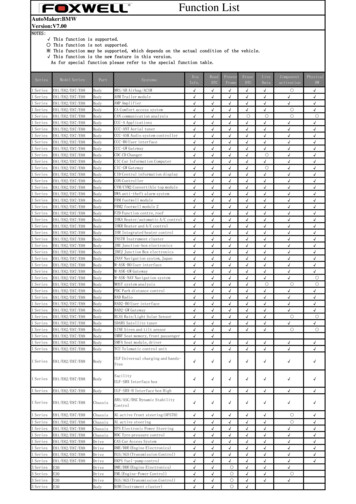
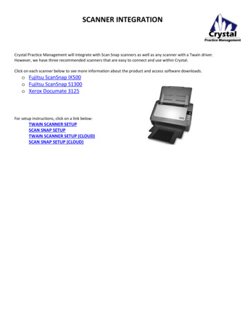
#define sane read be sane readWith definitions of this kind, backend be will export function name be sane read(). Thus, allbackends will export unique names. As long as a meta backend knows about these names, it is possibleto combine several backends at link time and select and use them dynamically at runtime. Dynamic linking: A simpler yet more powerful way to support multiple backends is to exploit dynamic linking on platforms that support it. In this case, a frontend is linked against a shared librarythat implements any SANE backend. Since each dynamically linked backend exports the same set ofglobal symbols (all starting with the prefix sane ), the dynamic library that gets loaded at runtimedoes not necessarily have to be the same one as one the frontend got linked against. In other words, itis possible to switch the backend by installing the appropriate backend dynamic library.More importantly, dynamic linking makes it easy to implement a meta backend that loads other backends on demand. This is a powerful mechanism since it allows adding new backends merely byinstalling a shared library and updating a configuration file. Network connection: Arguably the ultimate way to attach to a scanner is by using the network toconnect to a backend on a remote machine. This makes it possible to scan images from any host inthe universe, as long as there is a network connection to that host and provided the user is permittedto access that scanner.machine Amachine Bdllsaneddllpnmmusteknetautolumpnm filesscannerhpqcamnetwork connectionscanner 1scanner 2video cameraFigure 3.1: Example SANE HiearchyThe above discussion lists just a few ways for frontends to attach to a backend. It is of course possible tocombine these solutions to provide an entire hierarchy of SANE backends. Such a hierarchy is depicted inFigure 3.1. The figure shows that machine A uses a dynamic-linking based meta backend called dll to9
access the backends called pnm, mustek, and net. The first two are real backends, whereas the last oneis a meta backend that provides network transparent access to remote scanners. In the figure, machine Bprovides non-local access to its scanners through the SANE frontend called saned. The saned in turnhas access to the hp and autolum backends through another instance of the dll backend. The autolummeta backend is used to automatically adjust the luminance (brightness) of the image data acquired by thecamera backend called qcam.Note that a meta backend really is both a frontend and a backend at the same time. It is a frontend from theviewpoint of the backends that it manages and a backend from the viewpoint of the frontends that access it.The name “meta backend” was chosen primarily because the SANE standard describes the interface fromthe viewpoint of a (real) frontend.3.2Image Data FormatArguably the most important aspect of an image acquisition system is how images are represented. TheSANE approach is to define a simple yet powerful representation that is sufficient for vast majority ofapplications and devices. While the representation is simple, the interface has been defined carefully toallow extending it in the future without breaking backwards compatibility. Thus, it will be possible toaccommodate future applications or devices that were not anticipated at the time this standard was created.A SANE image is a rectangular area. The rectangular area is subdivided into a number of rows and columns.At the intersection of each row and column is a quadratic pixel. A pixel consists of one or more samplevalues. Each sample value represents one channel (e.g., the red channel). Each sample value has a certainbit depth. The bit depth is fixed for the entire image and can be as small as one bit. Valid bit depths are 1,8, or 16 bits per sample. If a device’s natural bit depth is something else, it is up to the driver to scale thesample values appropriately (e.g., a 4 bit sample could be scaled by a factor of four to represent a samplevalue of depth 8).3.2.1Image TransmissionThe SANE API transmits an image as a sequence of frames. Each frame covers the same rectangular areaas the entire image, but may contain only a subset of the channels in the final image. For example, ared/green/blue image could either be transmitted as a single frame that contains the sample values for allthree channels or it could be transmitted as a sequence of three frames: the first frame containing the redchannel, the second the green channel, and the third the blue channel.Conceptually, each frame is transmitted a byte at a time. Each byte may contain 8 sample values (for animage bit depth of 1), one full sample value (for an image bit depth of 8), or a partial sample value (for animage bit depth of 16 or bigger). In the latter case, the bytes of each sample value are transmitted in themachine’s native byte order. For depth 1, the leftmost pixel is stored in the most significant bit, and therightmost pixel in the least significant bit.Backend Implementation NoteA network-based meta backend will have to ensure that the byte order in image data is adjustedappropriately if necessary. For example, when the meta backend attaches to the server proxy,10
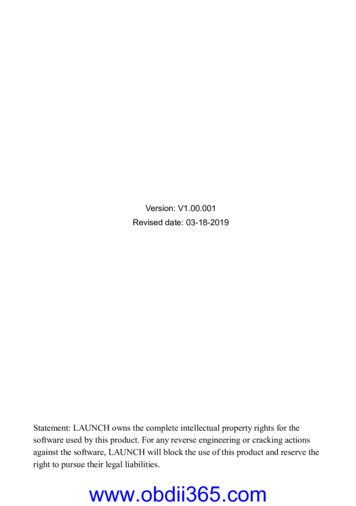
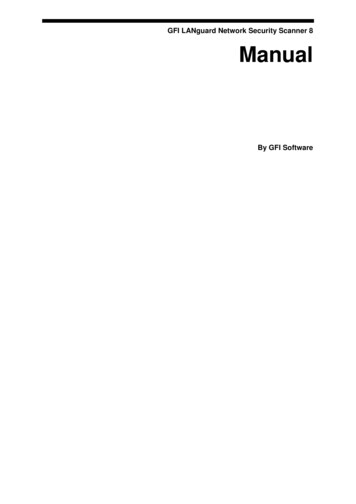
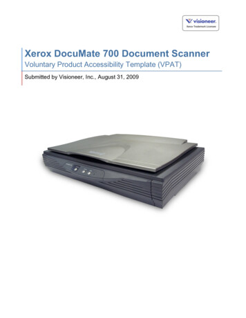
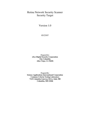
the proxy may inform the backend of the server’s byte order. The backend can then apply theadjustment if necessary. In essence, this implements a “receiver-makes-right” approach.Figure 3.2: Transfer order of image data bytesThe order in which the sample values in a frame are transmitted is illustrated in Figure 3.2. As can be seen,the values are transmitted row by row and each row is transmitted from left-most to right-most column. Theleft-to-right, top-to-bottom transmission order applies when the image is viewed in its normal orientation(as it would be displayed on a screen, for example).If a frame contains multiple channels, then the channels are transmitted in an interleaved fashion. Figure 3.3illustrates this for the case where a frame contains a complete red/green/blue image with a bit-depth of 8.For a bit depth of 1, each byte contains 8 sample values of a single channel. In other words, a bit depth 1frame is transmitted in a byte interleaved fashion.pixel 0bit: 7 6 5 4 3 2 1 0pixel 17654321076543210rgbbyte0byte1byte 2765432107654321076543210rgbbyte 3byte 4byte 5.Figure 3.3: Bit and byte order or image dataWhen transmitting an image frame by frame, the frontend needs to know what part of the image a framerepresents (and how many frames it should expect). For that purpose, the SANE API tags every frame witha type. This version of the SANE standard supports the following frame types:SANE FRAME GRAY: The frame contains a single channel of data that represents sample values from a spectral band that covers the human visual range. The image consists of thisframe only.SANE FRAME RGB: The frame contains three channels of data that represent sample valuesfrom the red, green, and blue spectral bands. The sample values are interleaved in theorder red, green, and blue. The image consists of this frame only.11
SANE FRAME RED: The frame contains one channel of data that represents sample valuesfrom the red spectral band. The complete image consists of three frames: SANE FRAME RED, SANE FRAME GREEN, and SANE FRAME BLUE. The order in which theframes are transmitted chosen by the backend.SANE FRAME GREEN: The frame contains one channel of data that represents sample valuesfrom the green spectral band. The complete image consists of three frames: SANE FRAME RED, SANE FRAME GREEN, and SANE FRAME BLUE. The order in which theframes are transmitted chosen by the backend.SANE FRAME BLUE: The frame contains one channel of data that represents sample valuesfrom the blue spectral band. The complete image consists of three frames: SANE FRAME RED, SANE FRAME GREEN, and SANE FRAME BLUE. The order in which theframes are transmitted chosen by the backend.In frames of type SANE FRAME GRAY, when the bit depth is 1 there are only two sample values possible,1 represents minimum intensity (black) and 0 represents maximum intensity (white). For all other bit depthand frame type combinations, a sample value of 0 represents minimum intensity and larger values representincreasing intensity.The combination
to access that scanner. hp qcam mustek pnm files scanner scanner 2 video camera machine A machine B network connection dll net saned dll autolum Figure 3.1: Example SANE Hiearchy The above discussion lists just a few ways for frontends to attach to a backend. It is of course possible to comb