Transcription
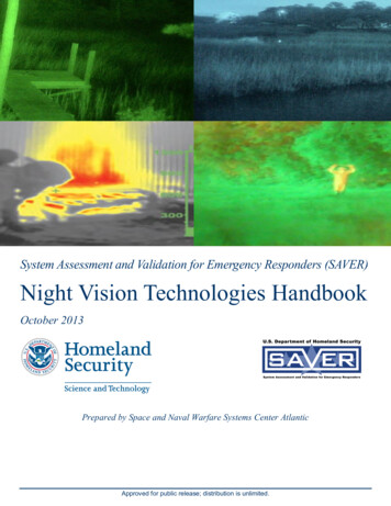
System Assessment and Validation for Emergency Responders (SAVER)Night Vision Technologies HandbookOctober 2013Prepared by Space and Naval Warfare Systems Center AtlanticApproved for public release; distribution is unlimited.
The Night Vision Technologies Handbook was funded under Interagency AgreementNo. HSHQPM-12-X-00031 from the U.S. Department of Homeland Security, Science andTechnology Directorate.The views and opinions of authors expressed herein do not necessarily reflect those of theU.S. Government.Reference herein to any specific commercial products, processes, or services by tradename, trademark, manufacturer, or otherwise does not necessarily constitute or imply itsendorsement, recommendation, or favoring by the U.S. Government.The information and statements contained herein shall not be used for the purposes ofadvertising, nor to imply the endorsement or recommendation of the U.S. Government.With respect to documentation contained herein, neither the U.S. Government nor any ofits employees make any warranty, express or implied, including but not limited to thewarranties of merchantability and fitness for a particular purpose. Further, neither theU.S. Government nor any of its employees assume any legal liability or responsibility forthe accuracy, completeness, or usefulness of any information, apparatus, product or processdisclosed; nor do they represent that its use would not infringe privately owned rights.Photographs and illustrations included herein were provided by Space and Naval WarfareSystems Center Atlantic under the Interagency Agreement, unless otherwise noted.Approved for public release; distribution is unlimited.
FOREWORDThe U.S. Department of Homeland Security (DHS) established the System Assessment andValidation for Emergency Responders (SAVER) Program to assist emergency respondersmaking procurement decisions. Located within the Science and Technology Directorate (S&T)of DHS, the SAVER Program conducts objective assessments and validations on commercialequipment and systems and provides those results along with other relevant equipmentinformation to the emergency responder community in an operationally useful form. SAVERprovides information on equipment that falls within the categories listed in the DHS AuthorizedEquipment List (AEL). The SAVER Program mission includes: Conducting impartial, practitioner-relevant, operationally oriented assessments andvalidations of emergency response equipment; and Providing information, in the form of knowledge products, that enablesdecision-makers and responders to better select, procure, use, and maintain emergencyresponder equipment.Information provided by the SAVER Program will be shared nationally with the respondercommunity, providing a life- and cost-saving asset to DHS, as well as to Federal, state, and localresponders.The SAVER Program is supported by a network of Technical Agents who perform assessmentand validation activities. Further, SAVER focuses primarily on two main questions for theemergency responder community: “What equipment is available?” and “How does it perform?”As a SAVER Program Technical Agent, the Space and Naval Warfare Systems Center(SPAWARSYSCEN) Atlantic has been tasked to provide expertise and analysis on key subjectareas, including communications, sensors, security, weapon detection, and surveillance, amongothers. In support of this tasking, SPAWARSYSCEN Atlantic conducted a review of nightvision technologies. Night vision technologies fall under AEL reference numbers04MD-01-LAMP: Equipment, Light Amplification and 03OE-02-TILA: Optics, ThermalImaging and/or Light Amplification.Visit the SAVER section of the Response Knowledge Base (RKB) website athttp://www.rkb.us/saver for more information on the SAVER Program or to view additionalreports on CCTV or other technologies.i
POINTS OF CONTACTSAVER ProgramU.S. Department of Homeland SecurityScience and Technology DirectorateOTE Stop 0215245 Murray LaneWashington, DC 20528-0215E-mail: saver@hq.dhs.govWebsite: http://www.rkb.us/saverSpace and Naval Warfare Systems Center AtlanticAdvanced Technology and Assessments BranchP.O. Box 190022North Charleston, SC 29419-9022E-mail: ssc lant saver program.fcm@navy.milii
TABLE OF CONTENTSForeword. iPoints of Contact . iiPreface . vi1. Introduction .11.1The Visible Light Spectrum .11.2History of Night Vision Technology .22. Night Vision Technology Reviews .32.1Image Intensification .32.2Thermography .72.3Near Infrared Illumination .92.4Integrated Night Vision. 102.5Emerging Technologies . 113. Applications . 113.1Law Enforcement Applications . 123.2Fire and Rescue Applications . 123.3Natural Resource Agency Applications . 133.4Security Applications . 143.5Engineering Applications . 143.6Medical Applications . 154. Acquisition Considerations . 154.1Common Night Vision Device Considerations . 154.2Image Intensifier Considerations . 174.3Thermal Imager Considerations . 194.4Integrated Night Vision Considerations. 205. Accessories . 205.1Eyeguards . 205.2Lens Adapters . 215.3Camera Adapters . 215.4NIR Illuminators. 215.5Sacrificial Window . 215.6Magnetic Compasses . 22iii
5.7Waterproof and Water-Resistant Night Vision Devices . 225.8Laser Range Finder . 225.9Headgear . 226. Vendor Matrix . 23Appendix A.Definitions . A-1LIST OF TABLESTable 6-1. Vendors and Types of Products . 23Table 6-2. Additional Vendors . 24LIST OF FIGURESFigure 1-1. I2 Display .1Figure 1-2. Visible Light and Infrared in the Electromagnetic Spectrum .1Figure 1-3. Night Glasses .2Figure 1-4. Gen 1 Starlight Scope.2Figure 1-5. Firefighter Using a Thermal Imaging Camera.3Figure 2-1. Multiple Technologies Scene Displays .3Figure 2-2. Gen 2 and Gen 3 Photomultiplier Tube Operating Principle .4Figure 2-3. I2 Display .4Figure 2-4. Gen 0 NVD .5Figure 2-5. Gen 1 NVD .5Figure 2-6. Gen 2 NVD .6Figure 2-7. Microchannel Plate .6Figure 2-8. White Phosphor Image .7Figure 2-9. Thermal Image of Vehicles .8Figure 2-10. Cooled Thermal Imaging Camera .9Figure 2-11. INVS Image . 10Figure 2-12. INVS Using Thermal Outline . 11Figure 3-1. I2 Image Display . 12Figure 3-3. Thermal Image Display of Fire Behind a Wall . 12Figure 3-2. Thermal Image of Residual Heat From A Hand On Wooden Fence . 12iv
Figure 3-4. Thermal Imaging Camera Display . 13Figure 3-5. Thermal Image Display of Overhaul . 13Figure 3-6. I2 Image Display . 13Figure 3-7. Security Truck using Mounted Thermal Imaging Camera . 14Figure 3-8. Thermal Image Display of an Engine . 14Figure 3-9. Thermal Medical Display of the Human Body. 15Figure 4-1. Monocular NVD . 17Figure 4-2. Binocular NVD . 17Figure 4-3. NVD Rifle Scope . 18Figure 4-4. NVD Goggles . 18Figure 4-5. 1951 USAF Resolution Target . 18Figure 4-6. Haloing Example . 19Figure 5-1. Eyeguard . 20Figure 5-2. Doubler Lens Adapter . 21Figure 5-3. Assault Rifle With Dual Beam Infrared Illuminator . 21Figure 5-4. Sacrificial Window . 21Figure 5-5. Headgear . 22v
Night Vision Technologies HandbookPREFACEThis Night Vision Technologies Handbook provides emergency responders, law enforcement,and security professionals with a reference on night vision technologies, capabilities, andlimitations. This handbook provides introductory-level information on the technologies andcomponents for night vision devices (NVDs), as well as an overview of their applications.Efforts to acquire or use an NVD should be undertaken only in consultation with organizationsor individuals experienced in this technology.This handbook examines NVDs and technologies for applications that include law enforcement,natural resource management, fire and rescue, emergency management, engineering, medical,and security services. The devices described include the following: Image intensifiers (I2); Thermal imaging cameras; Integrated night vision systems (INVSs); and Near infrared (NIR) illuminators.This handbook also discusses NVD operating principles and products, and the performancefactors and other attributes to consider when selecting an NVD. In addition, this handbookprovides a history of NVDs, a list of accessories for use with NVDs, and a brief discussion ofemerging night vision technologies. A vendor/product matrix is provided to identify theproducts found in the market research. The matrix is not intended to be an all-inclusive list ofequipment suppliers or products, and NVDs under development or restricted to military use arenot included in the matrix. Definitions of terminology commonly used and/or associated withnight vision technologies are provided at the end of the handbook.vi
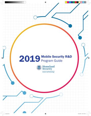
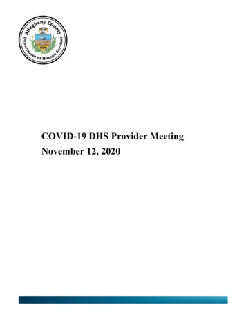
Night Vision Technologies Handbook1.INTRODUCTIONA night vision device (NVD) is an electro-opticaldevice that enhances vision in environmentalconditions with little or no light. Since WorldWar II, NVDs have been used by militaryorganizations as a force multiplier, greatlyextending military operational capabilities innighttime or low-light scenarios. NVDtechnology is used by many non-militaryagencies, such as law enforcement, fire, andsearch and rescue. NVDs include ImageFigure 1-1. I2 DisplayIntensifier (I2) devices, thermal imaging cameras,integrated night vision systems (INVSs), andCourtesy of ITTnear infrared (NIR) illuminator technology. Anexample of an I2 display is shown in Figure 1-1. NVDs can enhance almost any emergencyresponse agency’s operational capability by enabling the user to perform one or more of thefollowing functions: Detection–detect an object in limited light; Recognition–recognize the object; and Identification–identify distinguishing features.A brief review of the electromagnetic spectrum and a history of NVDs are provided to assist thereader in understanding how NVDs can enhance emergency responders’ capabilities.1.1The Visible Light SpectrumVisible light represents a narrow band of the greater electromagnetic spectrum, as shown inFigure 1-2. The visible spectrum contains all colors from violet to red. Each of the colors in thevisible spectrum has its own characteristic wavelength. The wavelengths of visible lightcorrespond to a range between approximately 400 (violet) and 700 (red) nanometers (nm). It isthe reflection of light within the visible wavelength that results in objects appearing in color tothe human eye. For example, objects appear green because all of the other observable colorwavelengths are absorbed by the objects surface except for green, which is reflected.Figure 1-2. Visible Light and Infrared in the Electromagnetic Spectrum1
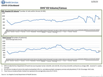
Night Vision Technologies HandbookNVDs are sensitive to sections of the electromagnetic spectrum, commonly called bands orfrequency bands, which are outside the range of human vision. Section 2 discusses how eachNVD technology utilizes a specific portion of the electromagnetic spectrum as defined by theNVD industry and depicted in Figure 1-2.1.2History of Night Vision TechnologyNight glasses were one of the first NVDs developed. They weresimple optical devices, similar to binoculars or a telescope, withlarge diameter objective lenses. Night glasses, such as those seenin Figure 1-3, had 55 millimeter (mm) or larger objective lensesand at least 7x magnification. They were heavy and oftendangerous to use because the pupil reflex of the eye is not fastenough to prevent damage from sudden exposure to a largeamount of light.Figure 1-3. Night Glasses1.2.1 Development of image IntensificationOther products developed during World War II include the cascade image tube and the infraredilluminator. Initial development efforts of I2 NVDs depended on active infrared illumination of atarget in order to operate. In combat or surveillance, active illumination devices have limitedusefulness, because they can reveal the source of light to an adversary using a device capable ofseeing infrared. These technologies are explained in more detail in Section 2.1.The I2 technology as it existed then is known as Generation 0 (Gen 0) I 2. The U.S. military usedthis type of device during the Korean War.The first passive military I2 NVDs were used duringthe Vietnam War. These Generation 1 (Gen 1) I2NVDs are known as starlight scopes as they usedambient light from the moon and stars to enhanceavailable lighting. These devices were bulky andcumbersome, but since they did not use any additionalillumination (i.e., infrared), the user’s location wasnot revealed. An example of a Gen 1 starlight scopeis shown in Figure 1-4.Figure 1-4. Gen 1 Starlight ScopePhoto by U.S. Army Center of Military HistoryProduced in the 1980s, Generation 2 (Gen 2) I 2 NVDs provided substantial improvements inperformance and packaging. Performance was improved by the addition of a microchannel plate(MCP) to the image-intensifier tube. The MCP resulted in images that were less distorted andbrighter than earlier-generation NVDs. The reduction in size and weight permitted the device tobe attached to a helmet or other headgear. Gen 2 devices are the most commonly available I2NVDs due to their record of performance and low relative cost.Generation 3 (Gen 3) I2 NVDs were developed in the late 1980s, and were used extensivelyduring the Gulf War in 1991. This generation NVD provided more light amplification and alonger service life than the prior generation NVDs. Gen 3 devices that amplify
Night Vision Technologies Handbook vi PREFACE This Night Vision Technologies Handbook provides emergency responders, law enforcement, and security professionals with a reference on night vision technologies, capabilities, and limitations. This handbook provides introductory-level information on the technologies andFile Size: 1MBPage Count: 34Discover on this pageWhich agency is responsible for saving emergency responders?Which screen is used by law enforcement?Which is better: P45 or P43?