Transcription
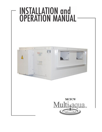
INSTALLATION & OPERATINGMANUALMCFCW Fan Coil 1- 5 Tons-------------------------------------- CAUTION -------------------------------------Care must be taken when handling sheet metal. Sheet metal parts have sharp edges and couldcause injury.GENERALRead the entire contents of this manualbefore beginning installation. Multiaquaassumes no responsibility for equipmentinstalled contradictory to any coderequirement or installation instructions.The components of this fan coil havebeen inspected at the factory and readiedfor shipment. Upon receiving theshipment, a visual inspection of thepackaging must be performed.If any damage to the packaging isdiscovered, an inspection of thecomponents must be performed andnoted on the delivery documents. Ifcomponent damage is found a damageclaim must be filed by the receiving partyagainst the delivery party immediately.This product is designed andmanufactured to permit installation inaccordance with national codes. It is theinstaller’s responsibility to install theproduct in accordance with nationalcodes and/or prevailing local codes andregulations.Care must be taken to ensure thestructural integrity of the supportingmembers, clearances and provisions forservicing,power supply, coil connectionsFigure 1and/orcondensateremoval. The (4HS)Figure 1model is high static up to .5”wc ESP. The(4LS) model is up to .3”wc ESP.Installation must allow for blower,motor and coil access from the bottomof the unit.This unit is designed to be installed in a horizontalconfiguration only. Before the installation ensurethe structural strength of the supporting membersis sufficient.See Figure 1 for hanging weights of the fan coils.See Figure 2 for filter sizes.See Figure 3 for fan coil dimensions.See Figure 4 for supply air opening dimension.See Figure 5 for mounting bracket dimension.See Figure 6 for return air opening dimension.See Figure 8 for water coil connections diagram.FAN COILWEIGHTS (LBS)MODEL 1MCFCW-20-4HS(LS)-0195100111144166176Figure 1RECOMMENDED FILTERSIZESWidth (in)Length (in)MCFCW-04-4HS(LS)-01 10.0025.0025.00MCFCW-06-4HS(LS)-01 10.0024.00 x 2 PIECESMCFCW-08-4HS(LS)-01 12.00MCFCW-12-4HS(LS)-01 12.0024.00 x 2 PIECES12.0024.00x 2 PIECESMCFCW-16-4HS(LS)-0130.00 x 2 PIECESMCFCW-20-4HS(LS)-01 16.00FAN COIL MODELNUMBERFigure 22
INSTALLATION & OPERATINGMANUALMCFCW Fan Coil 1- 5 TonsFAN COIL DIMENSIONS (in.)Fan CoilModel 2137.224.25 39.25 26.00 25 39.25 26.00 .25 48.00 49.00 12.00MCFCW-12-4HS(LS)-0133.00 12.0012.2529.2154.9224.25 48.00 49.00 12.00MCFCW-16-4HS(LS)-0133.00 12.0014.1731.5854.9224.25 57.00 49.00 12.00MCFCW-20-4HS(LS)-0133.00 12.0014.1731.5866.9327.00 69.00 61.00 16.00Figure 3ABCSupply DuctFigure 4GDFigure 5Mounting NotchesE3FI
INSTALLATION & OPERATINGMANUALMCFCW Fan Coil 1- 5 TonsHReturnIFigure 6Filter AccessDoorsRETURN AIR CONNECTIONSFilters are not supplied with the fan coil unit. The filter(s) must be supplied by the installer. Filtersize is displayed in Figure 2. To access filter door, swing out thumb tabs to open position.Refer to Figure 6Air InletFigure 7Air OutletElectrical/ControlBox4
INSTALLATION & OPERATINGMANUALMCFCW Fan Coil 1- 5 TonsELECTRICAL & CONDENSATE DRAINThere is one entry point for the electrical wiring. See figure 7. See unit Wiring Diagram for electrical drawings.Wiring must be installed according to prevailing codes and regulations.The fan coil unit has one primary condensate drain connection and one secondary safety drain connection. Theseare located on the coil connection side of the fan coil. See figure 8. A field supplied and installed P-Trap must beinstalled on both the primary and secondary drain lines. Make certain the gravity drain has at least 1/8” per footfall for proper drainage. Ensure the condensate traps and drains are properly insulated to avoid sweating.WATER COIL CONNECTIONSThe fan coil unit comes with a manual air bleed and a manual coil drain fitting. They are located on the same sideas the supply and return water line connections. When facing the water supply lines the hot water supply is on thetop left and return is on the bottom left. The cold water supply is on the top right and return is on the bottomright. Ensure that both the supply and return water lines are insulated to prevent them from sweating and capacityloss.Refer to Figure 8 and 9Cold Water SupplyHot Water SupplyAir InletAir OutletCold Water ReturnHot Water ReturnFigure 8Condensate DrainSecondary Safety DrainConnectionManual Air BleedFigure 95
INSTALLATION & OPERATINGMANUALMCFCW Fan Coil 1- 5 TonsMAINTENANCE1. Air Filter(s):Filters are an essential part ofthe quality of air that isprovided to the occupants.Never operate HVACequipment without filters.Filters help remove dust andunwanted particles from the airstream, helping to keep thespace clean. They also keep thisdebris from collecting on theheat transfer surfaces of theunit thus maintaining optimumequipment efficiency andperformance. These filters canbe located either in the unit’sfilter rack (see figure 6) orupstream from the unit in thereturn air ductwork. Filtersmust be inspected, cleanedand/or changed routinely. Thisroutine maintenance procedurewill allow the unit tocontinually operate as designed,reduce service expenses andextend equipment/componentlife.2. Fuses and/or CircuitBreakers:This unit must be connectedto the buildings electric servicein accordance withlocal/national electrical codesand regulations. Theseelectrical connections willinclude over current protectionin the form of fuses or circuitbreakers. Have your contractoridentify/label the circuits andthe location of them so that youmay be in a position to makeinspectionsand/or replacements in the event theunit fails to operate or is beingserviced. If fuses are used, ensurethat the replacement fuses are of thesame size and type as the ones youare replacing. It is a good idea tokeep replacement fuses of theappropriate size and type on hand.3. Routine Check Up and Service:This product is designed toprovide many years of dependable,trouble free comfort when properlymaintained. Proper maintenancewill consist of routine filtercleanings/changes, cleaning of theprimary and secondary drain linesand traps, bi-annual check- ups thatinclude but not limited to filterinspections, electric heaterinspections /cleaning of the internalelectrical and heat transfercomponents by a qualified servicetechnician. Failure to provideperiodic checkups and cleaning canresult in excessive operating cost,early component failure anddecrease the equipment’s lifespan.Blower wheel and motor areaccessible from the bottom of theunit only.6
INSTALLATION & OPERATINGMANUALMCFCW Fan Coil 1- 5 TonsWIRING DIAGRAM7
The fan coil unit has one primary condensate drain connection and one secondary safety drain connection. These are located on the coil connection side of the fan coil. See figure 8. A field supplied and installed P-Trap must be installed on both the primary and secondary drain lines.