Transcription
OASIS Heating SystemInstallation andOperating ManualDiesel and AC Heating Systemfor Recreational Vehicles and YachtsCSA TIL R-17ANSI/UL307ACAN/CSA-C22.2 No.165
Copyright January 2011, Revised August 2016International Thermal ResearchIN CANADA:IN THE UNITED STATES:2431 Simpson Road5305 NE 126th Ave, Suite 401Richmond, BC, CanadaV6X 2R2Vancouver, WA, USA98682Tel:1-800-755-1272 or 604-278-1272Tel:1-800-993-4402 or 360-993-4877Fax:604-278-1274Fax:360-993-1105Email: info@itrheat.comWebsite: http://www.itrheat.comAll rights reserved. No part of this manual may be reproduced ortransmitted in any form by any means, electronic or mechanical,including photocopying and recording, information storage,retrieval, or transmission, without permission in writing fromInternational Thermal ResearchRight to Modify:Due to our commitment for quality and ongoing productimprovement, ITR reserves the right to modify or changewithout notice, any materials, applications, equipment,accessories, and/or prices. All measurements and weights areapproximate.
Table of ContentsSection 1, Overview . 1-11.11.21.31.41.51.6Unpacking the Heating Module . 1-2Protect Your Warranty . 1-2Oasis Heating Module Features . 1-3Critical Factors . 1-5Equipment, Tools and Skills . 1-6Testing and Inspection . 1-7Section 2, Mounting the Oasis Heating Module . 2-12.12.22.32.42.5Before You Begin . 2-1Identifying Your Oasis Heating Module Model. 2-2Your Mounting Location . 2-2What NOT to Do . 2-4Procedure . 2-4Section 3, Installing the Exhaust System. 3-13.13.2Before You Begin . 3-1Mounting Location. 3-1Recommended Exhaust Outlet Locations.3-1Recommendation for Installation .3-2What NOT to Do .3-43.3Procedure . 3-4Section 4, Installing the Fuel System. 4-14.14.2Before You Begin . 4-1Fuel System Operation . 4-1Recommendations for Installation.4-14.34.4What NOT to Do . 4-2Procedure . 4-3Section 5, Installing Fan Heaters . 5-15.1International Thermal ResearchBefore You Begin . 5-1iii
Table of Contents5.2Fan System Operation .5-2Features .5-2Multiple Zone Heating .5-3Accessories and Components Needed .5-35.35.45.5What NOT to Do .5-4Mounting Locations.5-4Procedure.5-5Section 6, Wiring the Electrical System . 6-16.16.26.36.46.56.66.7Before You Begin.6-112 VDC .6-1120 VAC.6-2Remote Operating Panel Cable .6-2Main Electronic Control Board .6-3Distribution Module Zone Control Board(Optional) .6-3What NOT to Do .6-4Section 7, Plumbing the System . 7-17.17.27.37.4Before You Begin.7-1Plumbing Installation .7-1What NOT to Do .7-4Installation Procedure .7-4Section 8, Operating the Oasis Heating Module . 8-18.18.28.38.48.58.68.78.88.98.10ivFeatures of your Oasis Heating Module .8-1Your Heating Module Model .8-2Operating Instructions for theOasis Heating Module.8-3Turning the Power to theOasis Heating Module ON .8-4Activating the Burner (Primary)and AC Heat (Secondary) from theRemote Operating Panel.8-5Activating the Cabin Fan Heatersthrough the Thermostats.8-6Activating the Domestic Hot Water .8-6Activating the Engine Heat .8-6Functions of the Remote Operating Panel .8-7Functions of the Heating Module Control Panel .8-9Installation and Operating Manual for OASIS Heating Module
Table of Contents8.118.128.138.14Functions of the Distribution Module (Optional)Zone Control Panel .8-10Maintenance .8-11Protecting the Heating Module andDistribution Module (Optional) .8-13General Troubleshooting .8-13Section 9, Installing Distribution Module, DM-12(optional) . 9-19.19.29.39.49.59.69.79.89.9Installing your Distribution Module (optional) . 9-1Selecting the Module Location . 9-1Selecting the Distribution ModuleZone Box Location . 9-2Plumbing Installation. 9-3Filling/Purging the heating loop . 9-7Electrical Connection . 9-8Distribution Module Zone Control Board. 9-9Inspection and Testing .9-12Hot water temperature adjustment .9-12Warranty Information & Warranty CardInternational Thermal Researchv
Table of ContentsList of FiguresFigure 1-1Figure 1-2Oasis Module .1-1Oasis Heating and Distribution Module .1-5Figure 2-1Figure 2-2Module Dimensions .2-3Module Mounting Brackets .2-5Figure 3-1Figure 3-7Installing the Exhaust System(Bottom Exhaust) .3-6The Exhaust Hole Location & MountingTemplate .3-6The Exhaust Goose neck Configuration .3-7Figure 5-1Figure 5-2Wiring the Fan’s Aquastat .5-2Mounting a Spacesaver Fan.5-6Figure 5-3Installing a Relay for Add’l Fan Amperage .5-6Figure 6-1System Wiring.6-3Figure 7-1Figure 7-2Heating Module .7-3Three Approved Methods of InstallingHeater Hose (consult ITR for alternativemethods and asis Heating Module .8-3Heating Module Main Control Panel .8-4Remote Operating Panel .8-7Zone Control Panel . 09-11Distribution Module .9-2Distribution Module Zone box .9-2Distribution Module Fittings Location .9-3Domestic Hot Water System Plumbing.9-4Engine Heat / Pre-heat System Plumbing.9-5Connecting to the OASIS Heating Module.9-5Connecting two Heating loops .9-6Initial fill up Oasis system .9-7Distribution Module Wiring . 9-10Zone Board Wiring (No Distribution module) . 9-11Mixing valve location . 9-12Figure 3-2viInstallation and Operating Manual for OASIS Heating Module
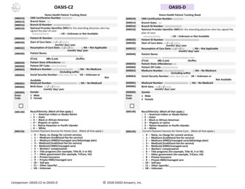
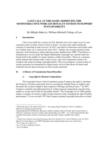
Section1OverviewThank you for purchasing therecreational vehicles and yachts.NOTICEOasis HeatingModuleforThe Oasis Heating Module is CSA certified only forinstallation into Recreational Vehicles, Manufactured Homes,and Mobile housing.This section covers critical information you need to know beforebeginning the installation including how to protect your Warranty,and tools and equipment needed.Figure 1-1: Oasis Heating ModuleInternational Thermal Research1-1
Section 1, Overview1.1Unpacking the Oasis Heating ModuleWhen you receive the Oasis Heating Module:1Unpack it carefully.2Check each component against the shipping list to ensure thatyou have everything and that all parts arrived undamaged.3If you discoverimmediately.4If you are not installing the Oasis Heating Module right awaysecure all components so none will be misplaced.5Before installing the Oasis Heating Module read the restof this Installation and Operating Manual. It containscritical information for a proper installation.anymissingordefectivepartscallA properly installed Oasis Heating Module is essential for severalreasons: To ensure that you and/or your customers receive satisfactoryresults and enjoy a warm, comfortable environment. To ensure a trouble-free installation, a successful inspection andtesting process, and ease of future maintenance. To protect your Warranty.1.2Protect Your WarrantyThis document reflects approved installation techniques, methods,and materials, and applies only to ITR equipment. The Oasis Heating Module is only guaranteed by ITR if the entire system hasbeen installed according to the requirements and recommendationsset out here.This includes: Deviations from the instructions in this Manual.Changes to any piece of ITR-supplied equipment.Substitution of a non-ITR approved component.No Warranty will be extended to improper installations. Use of anyunapproved materials, equipment or installation procedures will1-2The Oasis Heating ModuleITR
Section 1, Overviewresult in a voided warranty for the entire heating system. Any lossof service or damage as a result of any unapproved modification isthe responsibility of the installer. ITR accepts no liability for anydamage or loss of service resulting from unapproved modifications. ical1.3Oasis Heating Module FeaturesThe Oasis Heating Module uses a diesel burner (12 VDC)controlled by a multi-functional electronic controller as the primarysource of heating coolant fluid (anti-freeze and water). Two 1500Watt, 120 VAC immersion elements are used as secondary heatsources. The Oasis Heating Module heats the coolant fluid toprovide a source of heat for all hydronic space heating needs.When used with the Distribution Module (optional) and its integraldistribution pumps, the Oasis Heating Module has the ability tocirculate the coolant fluid to all space heating areas. It can alsoprovide a supply of domestic hot water using the integral heatexchanger in the Distribution Module. The Oasis also incorporatesengine heat and preheat functions. (see Figure 1-2:Oasis Heating and Distribution Modules).Other features of the Oasis Heating Module include: A high-temperature, stainless steel burner and stainless steeljacket. 9.5 US gallon welded, insulated stainless steel coolant tank thatminimizes heat loss and optimizes heat recovery. Low coolant level switch on the tank. Easy to install, completely modular and field serviceable with theOasis Heating Module hookups and connections easilyaccessible from the front and top of the Heating Module. Quiet operation and low power consumption. Low pressure fuel system with built-in fuel pump. Fuel efficient burner capable of burning a wide variety of dieselbased fuels. Exhaust has minimal smoke and smell.International Thermal Research1-3
Section 1, Overview Fan assisted sealed combustion chamber is designed to useoutside combustion air. Simple, low amperage draw ignition. Electronically-controlled system with: automatic Safety Shutdown;manual-resettable aquastats for safety overheat protection.LED indicators on the Control Panel for diagnostics.Patented, proprietary flame sensor. Heating Module Remote Operating Panel with ON/OFF switch forthe diesel burner, AC elements, and engine heat, if installed. Heating Module Control Panel with buttons for Power, Bypass,Reset, and indicator LED’s for operational and diagnosticinformation. Distribution Module if installed with built in distribution pumpsand heat exchanger for heating multiple zones and alsoproducing domestic hot water. Heat exchanger also allowsengine pre-heating as well as using engine waste heat. The ZoneBoard Controls up to five space heating zones.Figure 1-2: Oasis Heating and Distribution Module1-4The Oasis Heating Module
Section 1, Overview1.4Critical FactorsTHE INSTALLATION SHALL BE IN ACCORDANCE WITH THEREGULATIONS OF AUTHORITIES HAVING JURISDICTIONPay attention to thenotices of “Danger”“Warning” “Caution”and “Notice” in thismanual.The key factors to keep in mind when planning and carrying out theinstallation are: Mounting location restrictions for the Oasis Heating Module,optional Distribution Module , and exhaust outlet (to reducenoise, vibration, heat loss, etc.). Length, routing and sizing of fluid lines, fuel lines, air-flowtubing, exhaust piping and wiring. Unrestricted vent required to draw in 100% outside air forcombustion. Ability for technician to easily access and service the product,especially fuel, plumbing, and electrical systems. After installation, ability to purge water and fuel lines andinspect/test entire system using the ITR-supplied InspectionCheck Sheet.1.5Equipment, Tools and SkillsAs the user and/or installer, you must be qualified and authorized todo the installation, which requires mechanical aptitude and electricalknowledge. Make sure you comply with existing RVIA or ABYCindustry practices, using the highest and most recent standards andcodes.Good workmanship is essential.Please refer back toSection 1 – Overview, sub-Section 1.2, Protect Your Warranty.You will need the following equipment and tools to install theheating system (not supplied). This list does not include optionalequipment and accessories: Standard tools normally available in a well-equipped shop. Approved fasteners for mounting the heater unit. Steel (or stainless steel) 2” ID exhaust system piping, maximum12’ with no bends. (See Section 3 – Installing the ExhaustSystem, for details when bend are present.).International Thermal Research1-5
Section 1, Overview Exhaust collar. ITR-muffler with straight-through design. 1/4” supply fuel line, approved rubber or copper. #10 sheet metal screws or wood screws to mount fan unitsinside the occupied areas. Heater hose (to connect optional Distribution Module hosefittings to interior fans). Domestic water hose and/or tubing to connect the DistributionModule hose fittings to the domestic water system. Overflow tank to connect to the Oasis Heating Module withclear plastic 3/8” hose; tank must be heavy-duty plastic, with ascrew-down cap, and sturdy enough to mount firmly to a verticalsurface. Up to five (5) thermostats (DC compatible) to allow temperatureregulation of the heating zones when connected to theDistribution Module.1.6Testing and InspectionAfter all components have been properly installed according tostandard practices, RVIA or ABYC standards, and therecommendations of this Installation and Operating Manual, theOasis Heating Module should be test-operated for inspectionpurposes.For your convenience, you can use the pullout Inspection CheckSheet in this Manual. The Inspection Check Sheet is divided intoprogressive sections, allowing each phase of the inspection to becarried out systematically, and then signed off by authorizedpersons.1-6The Oasis Heating Module
Section 1, OverviewInternational Thermal Research1-7
Section2Mounting – Oasis HeatingModule2.1Before You BeginPlan the location of the Oasis Heating Module and all its majorcomponents in advance to ensure the chosen locations arecompatible with installation requirements and within the technicalspecifications.Consider the following factors to help you decide exactly wherebest to mount the Oasis Heating Module:International Thermal Research Oasis Heating Module weight when full (160 lbs). Ventilation requirements. Exhaust outlet location and maximum acceptable length. Thru hull location and waterline (yachts). Potential for vibration and jarring. Length of run from fuel source to heater. Most efficient plumbing runs. Safe and convenient access for maintenance. Number and location of interior fans. Location of other equipment to be installed or connected tothe Oasis Heating Module, including the optionalDistribution Module, Zone Control Box, heat exchangers,overflow tank, batteries, etc.2-1
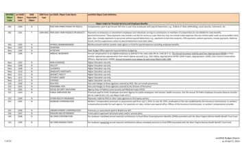
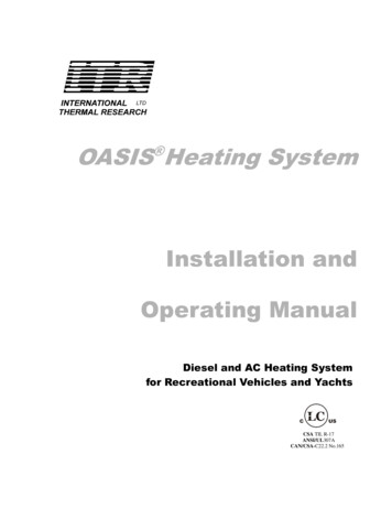
Section 2, Mounting the Oasis Heating Module! WARNINGMake sure you are familiar with Section 1 – Overview of thisManual. If the system is not installed according to specificationsand with the correct equipment, your Oasis Heating Module maynot operate properly, safety may be compromised, and yourWarranty may be voided.2.2Identifying YourModule ModelOasis HeatingAs the owner, you must be fully aware of the controls andoperating features particular to your model of the Oasis HeatingModule. This is essential for the proper functioning and life of yourOasis Heating Module as well as protecting your warranty. Yourmodel can be identified by locating the serial number label on theoutside case of the Oasis Heating Module. The serial numberidentifies the model type through the first series of letters andnumbers.The types of Oasis Heating Module models are:CH50S – Oasis Heating Module (Stainless Steel Case)CH50B – Oasis Heating Module (Galvanized Case)2.3Your Mounting LocationYour mounting location should consider the following:2-2 Mounting location must be able to support double the grossweight of the Oasis Heating Module (i.e. 160 lbs. x 2 320lbs./73 KG x 2 146 KG) and must be of a noncombustible and non absorptive surface. Oasis Heating Module is 14”H x 14”W x 30” D. (35.6 cm x35.6 cm x 76.1 cm), see Figure 2-1: Module Dimensions. Oasis Heating Module must be installed in a compartmentwhich is completely isolated from the atmosphere of livingspaces. Combustion air must be drawn from an outside source andcannot contain any combustible gases.The Oasis Heating Module
Section 2, Mounting the Oasis Heating Module Oasis Heating Module must be mounted in an area thatprovides unrestricted access to the front panel. Allow space forconnection to the fuel and coolant lines, as well as the powerand exhaust connections. (Minimum of 10” top clearance - topexhaust version; minimum of 6” top clearance - bottomexhaust version; 0” clearance to all other Oasis HeatingModule surfaces). Allow 1” clearance on the sides for attachingthe mounting brackets. Mount the unit with the front panel side facing out andaccessible. Facing out simplifies installation and maintenance. Oasis Heating Module must be mounted horizontal and levelusing eight, 1/4” through bolts and 1” diameter fenderwashers, lock washers and nuts.Figure 2-1: Module Dimensions! DANGER! WARNINGOasis Heating Module must not be installed or operated in anycompartment with flammable gases.If the Oasis Heating Module is going to be mounted in the enginecompartment, check for adequate ventilation. When the engine isrunning this area could be under a negative pressure. Make surethe air-intake and exhaust hoses have no leaks and are wellfastened to the heater, muffler and thru-hull fitting. Assemblyparts that may cause injury through accidental contact should beprotec
Aug 31, 2016 · OASIS Heating System . including photocopying and recording, information storage, retrieval, or transmission, without permission in writing from International Thermal Research Right to Modify: . 3 If you discover any missing