Transcription
INSTALLATIONINSTRUCTIONS 2017 Lennox Industries Inc.Dallas, Texas, USAHarmony III Zoning SystemZONING505,023M5/2017Supersedes 7/2015THIS MANUAL MUST BE LEFT WITH THE HOMEOWNERFOR FUTURE REFERENCEWARNINGImproper installation, adjustment, alteration, service ormaintenance can cause personal injury, loss of life, ordamage to property.Installation and service must be performed by a licensedprofessional installer (or equivalent) or a service agency.Table of ContentsGENERALIntroduction . . . . . . . . . . . . . . . . . . . . . . . . . . . . . . . . . . . . . . . . . . . . . .Optional Dehumidification Accessories . . . . . . . . . . . . . . . . . . . . . . .Residential Zone Control System - Field Wiring . . . . . . . . . . . . . . . .System Components (included and separately ordered) . . . . . . . . .Installation planning and selecting heat/cool equipment . . . . . . . . . .Installing Zone Control Components . . . . . . . . . . . . . . . . . . . . . . . . . .Zone Control Panel Jumpers:General Information . . . . . . . . . . . . . . . . . . . . . . . . . . . . . . . . . . . .Air Reduction . . . . . . . . . . . . . . . . . . . . . . . . . . . . . . . . . . . . . . . . .Air Reduction . . . . . . . . . . . . . . . . . . . . . . . . . . . . . . . . . . . . . . . . .Heat/Cool Staging . . . . . . . . . . . . . . . . . . . . . . . . . . . . . . . . . . . . . .SYSTEM Configuration/E-Heat Stages . . . . . . . . . . . . . . . . . . . .Common System Component Wiring . . . . . . . . . . . . . . . . . . . . . . . . .Zone Control Transformer Phasing . . . . . . . . . . . . . . . . . . . . . . . . . . .Component Specific Wiring . . . . . . . . . . . . . . . . . . . . . . . . . . . . . . . . .Minimum CFM in Variable Speed Furnaces . . . . . . . . . . . . . . . . . . . .System Flow Diagrams . . . . . . . . . . . . . . . . . . . . . . . . . . . . . . . . . . . .22345689910111213131415HEAT PUMPInstalling Heat Pump and accessories . . . . . . . . . . . . . . . . . . . . . . . .Zone control system wiring—Heat Pump . . . . . . . . . . . . . . . . . . . . . .Heat Pump System Startup and Checkout . . . . . . . . . . . . . . . . . . . .Heat Pump Heating Checkout - Single Zone . . . . . . . . . . . . . . . .Heat Pump Heating Checkout - Multiple Zone . . . . . . . . . . . . . . .Heat Pump Heating Checkout - Central Control . . . . . . . . . . . . .Heat Pump Pressure Switch Checkout . . . . . . . . . . . . . . . . . . . .Troubleshooting:Zoning system with Heat Pump . . . . . . . . . . . . . . . . . . . . . . . . . . .HP Heating Operation . . . . . . . . . . . . . . . . . . . . . . . . . . . . . . . . . .Defrost Operation . . . . . . . . . . . . . . . . . . . . . . . . . . . . . . . . . . . . . .16171818191920212223GAS FURNACEZone control system wiring—Gas Furnace . . . . . . . . . . . . . . . . . . . .G71MPP/SLP98/SL280V/EL296V:Integrated Control Electrical Adjustments . . . . . . . . . . . . . . . . . .System operation . . . . . . . . . . . . . . . . . . . . . . . . . . . . . . . . . . . . . .Installation setup worksheet . . . . . . . . . . . . . . . . . . . . . . . . . . . . .G61MPV/G60UHV:Integrated Control Electrical Adjustments . . . . . . . . . . . . . . . . . .System Operation . . . . . . . . . . . . . . . . . . . . . . . . . . . . . . . . . . . . . .Installation setup worksheet . . . . . . . . . . . . . . . . . . . . . . . . . . . . .24252627293133Gas Furnace Start-Up and Checkout:Gas Heating Checkout - Single Zone . . . . . . . . . . . . . . . . . . . . . .Gas Heating Checkout - Multiple Zone . . . . . . . . . . . . . . . . . . . . .Gas Heating Checkout - Central Control . . . . . . . . . . . . . . . . . . .Troubleshooting:Zoning system with Gas Furnace . . . . . . . . . . . . . . . . . . . . . . . . .Gas Heating Operation . . . . . . . . . . . . . . . . . . . . . . . . . . . . . . . . .Discharge Air Upper Limit and Differential Temp. . . . . . . . . . . . .343535363738AIR HANDLERSVariations on common condensing unit applications:Electric Heat, Hot Water Coil, Cooling Only . . . . . . . . . . . . . . . . .Air Handler Settings (All applicable models) . . . . . . . . . . . . . . . . . . .Installation Setup ting; ElectricStrip Heat (non-HP appls) . . . . . . . . . . . . . . . . . . . . . . . . . . . . . . .CBX25UHV/CBX32MV/CBX40UHV—Heat Pump;Electric Strip Heat . . . . . . . . . . . . . . . . . . . . . . . . . . . . . . . . . . . . . .CBX25UHV/CBX32MV/CBX40UHV – Cooling Only or Coolingwith Hot Water Coil (non-HP appls) . . . . . . . . . . . . . . . . . . . . . . .3940424344DUAL FUELZone control system wiring—Dual Fuel . . . . . . . . . . . . . . . . . . . . . . .Dual Fuel Startup and Checklist . . . . . . . . . . . . . . . . . . . . . . . . . . . . .Gas Heating Checkout - Single Zone . . . . . . . . . . . . . . . . . . . . . .Gas Heating Checkout - Multiple Zone . . . . . . . . . . . . . . . . . . . . .Gas Heating Checkout - Central Control . . . . . . . . . . . . . . . . . . .Troubleshooting:Zoning system with Dual Fuel . . . . . . . . . . . . . . . . . . . . . . . . . . . .Dual Fuel Operation (Below Balance Point) . . . . . . . . . . . . . . . . .Discharge Air Upper Limit and Differential Temperatures . . . . . .Dual Fuel Operation (Above Balance Point) . . . . . . . . . . . . . . . .Defrost Operation . . . . . . . . . . . . . . . . . . . . . . . . . . . . . . . . . . . . . .Installation Setup Worksheets:G61MPV/G60UHV Dual Fuel; withHoneywell 2-stage IFC control (HP appls) . . . . . . . . . . . . . . . . . .G71MPP/SLP98/SL28V0/EL296V Dual Fuel (HP appls) . . . . . .454646474849505152535455TROUBLESHOOTINGOperation and Troubleshooting Indicators . . . . . . . . . . . . . . . . . . . . .Fault Recall. Time Delays, Time Delay Override . . . . . . . . . . . . . . . .Diagnostics Codes . . . . . . . . . . . . . . . . . . . . . . . . . . . . . . . . . . . . . . . .Troubleshooting Air Delivered by Blower . . . . . . . . . . . . . . . . . . . . .PIAB Calculation Worksheet . . . . . . . . . . . . . . . . . . . . . . . . . . . . . . . .5758596163
GENERALGENERALShipping and Packing ListItems shipped with the Harmony III zoning system in clude:1 - Harmony III zoning system unit1 - Discharge Air SensorAdditional items—ordered separately; include (see Sys tem Components on Page 4): Transformer Dampers Thermostats Balance Point Sensor kit (56A87) Pressure switch (For Heat Pump Option):HFC-22 (27W12); HFC-410A (27W13) Tee for vapor line High Pressure Switch (87071) Defrost Tempering Kit (67M41) Humiditrol Enhanced Dehumidification Accessory(EDA), EDA-024B (94M41), EDA-036C (94M42),EDA-060D (94M43) Humiditrol Zoning Accessory (HZA) Kit (39W67) (re quired if Humiditrol EDA, above, is used)IntroductionIMPORTANTVariable Speed Blower Motor (VSM) technology is re quired for use with Harmony III zoning system.WARNINGThis product contains a chemical known to the State ofCalifornia to cause cancer, birth defects, or otherreproductive harm.The Lennox Harmony III zoning system manages thedistribution of conditioned air to specific areas or zones in ahouse or small commercial building by directing heated orcooled air to occupied areas without conditioning unusedareas. This improves economy while providing a balancedand comfortable environment. The system can be used inthe following Lennox HVAC system applications:Option 1.Variable speed gas furnace used with a 2‐stagecondensing unit.*505023MOption 2.Variable speed air handler unit (with or withoutelectric heat) used with a 2‐stage condensingunit or heat pump.*Option 3.Variable speed gas furnace used with a 2‐stageheat pump.**A 1 stage condensing unit (heat pump) may be used under specificcircumstances as listed in Table 3 (see Page 5).Variations on the options described above and included inthis document are: cooling-only, hot water coil, and coolingsystem with electric heat applications.The Harmony III zoning system uses off-the-shelf,single‐stage, non‐heat pump, non-power‐robbing elec tronic thermostats and motorized dampers in any of theapplications to control distribution of conditioned air to dif ferent zones. This control allows conditioning of differentzones within a residence while using a single HVAC sys tem.The zone control system operates in two modes: centralcontrol (vacation mode) or zone control. LEDs on thezone control panel indicate the current operating mode.When the system is in the central control mode, a de mand from the central control thermostat results in condi tioned air being directed to all of the zones. In this mode,zone 1 thermostat is designated as the controlling thermo stat; other thermostats are not used.When the system is in the zone control mode, a zone isconditioned only upon demand from that zone's thermo stat.The zone control system is ideal for retrofit applications aswell as new construction. The system controls the air vol ume, eliminating the need for bypass dampers in most ap plications. The homeowner controls the system usingzone thermostats to make comfort settings for each zone.A programmable thermostat should be used to provide aspecialized heating and cooling sequence. While the sys tem is in the zone mode, a programmable thermostat con trols the temperature for its particular zone.Optional Dehumidification AccessoriesThe Harmony III zoning system may be used in conjunc tion with a Humiditrol Enhanced Dehumidification Accesso ry (EDA) and which also requires a Humiditrol Zoning Ac cessory (HZA). This document reflects the control which isoutfitted for connection to, and control of, the EDA in azone control system using the HZA. See Humiditrol Zon ing Accessory Installation Instructions for more informa tion.Page 2
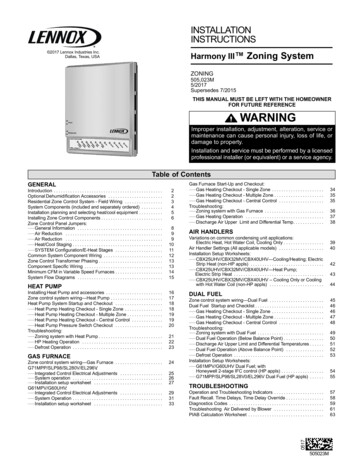
GENERALResidential Zone Control System - Overview of Field WiringTHERMOSTAT (ZONE 1 OR CENTRAL CONTROLTHERMOSTAT WHEN IN VACATION MODE)ZONE DAMPERPOWERTRANSFORMER TO POWERZONE CONTROL PANEL, THER MOSTATS AND DAMPERS;ALSO POWERS HZA CONTROLWHEN EDA IS USED)HUMIDITROL ENHANCEDDEHUMIDIFICATIONACCESSORYHUMIDITROL ZONINGACCESSORY (HZA)OPTIONALTHERMOSTAT(ZONE)ZONE DAMPERZONE 1ATHERMOSTAT(ZONE)BBZONE DAMPERDCONDENSINGUNIT OR HEATPUMP OUT DOOR UNITBFEFGHDISCHARGEAIR SENSORZONE CONTROLSYSTEM PANELEAATHERMOSTAT(ZONE)BBZONE DAMPERCH*ZONE 4*ZONE 3LEGEND ABCDZONE 2AGVARIABLE SPEEDFURNACE OR AIRHANDLEROUTDOORTHERMOSTAT /Five wire low voltage — 18 ga. minimumBALANCETwo wire low voltage OR Three wire if Power-open, Power-closed — 18 ga. minimumPOINT SENSORINDOOR UNIT: Up to nine wire low voltage — 18 ga. minimumOUTDOOR UNIT:- Two (3, if LSOM equipped unit) wire low voltage (single‐stage condensing unit or EDA) 18 ga. minimum- Three (4, if LSOM equipped unit) wire low voltage (two‐stage condensing unit) 18 ga. minimum- Up to seven wire low voltage (single‐stage heat pump outdoor unit) 18 ga. minimum- Up to eight wire low voltage (two‐stage heat pump outdoor unit) 18 ga. minimumTwo wire low voltage (discharge air sensor) 18 ga. minimumTwo wire low voltage (pressure switch, heat pump only) — 18 ga. minimumTwo wire — 18 ga. minimumRefer to the Humiditrol Zoning Accessory (HZA) for wiring requirements.*NOTE - Zone 3 and zone 4 not available with single‐stage outdoor unit.Page 3HARMONY III ZONING SYSTEM
GENERALSystem ComponentsThe Harmony III zoning system consists of the following(ѵ - required):ѵ Harmony Harmony III zoning system zone control panelѵѵѵѵѵ (included)Discharge Air sensor (included)Thermostats (1 for each zone; ordered separately)24VAC Power Transformer(s) (ordered separately)Dampers (ordered separately)Pressure Switch and Tee w/Schrader valve (for Heat Pumpsystems; ordered separately)Balance Point Sensor (Optional for Dual Fuel sys tems)Defrost Tempering Kit (Optional for Dual Fuel sys tems)Remote Vacation Switch (optional; ordered separate ly)Zone Control SystemThe Harmony III zoning system monitors electrical sig nals and directs control signals between thermostats,dampers, and HVAC equipment (see figure 1).DAMPERCONNEC TIONSPRESSURESWITCH CON OR THERMOSTAT /BALANCE POINT SENSORCONNECTIONSTEMPERATURE/RESISTANCE CHARTRESISTANCE (OHMS)TEMP 907,3321005,826Figure 2. Discharge Air SensorThermostatsIMPORTANTRoom thermostat MUST BE configured Heat/Coolthermostat only.For all zones, use thermostats that are of this type: electronic thermostat single‐stage non‐heat pump non‐power robbing autochangeover or non-autochangeover Lennox recommends that zone 1 thermostat (central[vacation] mode controller) be programmable. Each thermostat must have a deadband betweenHEAT and COOL.Recommended thermostats include:IMPORTANTJUMPERS:STAGINGTEMP Use only Electronic thermostats. Mechanical or electro‐mechanical thermostats will not work with the HarmonyIII zoning ONCONT.-- HEATING-DISCHARGEAIR SENSORCONNECTIONSSYS CONFIG ANDE-HEAT JUMPERSTIMEDELAYREMOTEOVER FAULTVACATIONRIDE RECALLSWITCH;DIAGNOSTICCONNECTIONSLEDSFOR HZAEQUIPMENTCONNECTIONS SYSTEM OPERATION LEDSFigure 1. Harmony III zoning system Zone ControlPanelDischarge Air Sensor (DAS)A discharge air temperature sensor (88K38) monitors thesupply air. This electronic sensor's probe is inserted intothe discharge air plenum to gather air temperature data forthe zone control panel. Figure 2 shows the kit; see figure 3(Page 6) for location of the sensor.505023MComfortSense 7500 (13H14) 7-Day ProgrammableTouch Screen Thermostat - 4 Heat / 2 Cool.IMPORTANT! When using this thermostat, only Pre cision Mode dehumidification can be used wherein2 F of over‐cooling is allowed. Also, it cannot reducethe blower speed because the zone control DS signalcontrols the blower. Thermostat D terminal is notused.ComfortSense 5500 (13H13) 7-Day ProgrammableTouch Screen Thermostat - 1 heat / 1 coolTransformerThe dampers, zone control panel, zone thermostats andHumiditrol Zoning Accessory (if EDA is used) are pow ered by a single, field-provided 24VAC transformer. To gether, the zone control panel and thermostats require10VA; dampers require 10VA each. The transformer musthave an adequate VA rating to serve all components (seerecommendations in table 1).Page 4
GENERALIf a “small” zone cannot be avoided, give consideration toincreasing the CFM of the small zone and linking a damperin a nearby zone that will open along with the small zone'sdamper(s). The procedure for zone linking is described onPage 7.Table 2. Adjusting for average CFM ExampleIMPORTANTUp to 5 dampers per zone may be connected in parallelto the zone control panel —not to exceed a total of sixdampers for entire system.Also, if more than 6 dampers are used, another trans former and isolation relay will be necessary.Required CFMZn1234Table 1. 24VAC Transformer selection chartCatalogNumberSizeDescriptionVA LOAD Panel plus-10P1740VA120/208/240VAC, 24VAC3 dampers10P8750VA120/208/240VAC, 24VAC4 dampers12P6175VA120/208/240VAC, 24VAC6 dampers83P74Electrical Box (4‐in. square)DampersMotorized 24VAC powered closed/spring return opendampers are standard for the Harmony III zoning sys tem. However, “power‐open/spring‐close” and “power‐open/power‐close” dampers can be accommodated.Remote Vacation SwitchThe Harmony III zone control panel includes connec tions for an optional remote vacation switch (see figure 1).The same connections are also used for connecting an op tional Humiditrol Zoning Accessory controller (see Humi ditrol Zoning Accessory Installation Instructions for de tails).NOTE - If a remote vacation switch is connected forrouting to a convenient location for end user opera tion, be sure the switch (field‐provided) is properly la beled and instructions provided for proper operation.DO NOT LOCATE THE REMOTE VACATION SWITCHNEXT TO OTHER HOUSE SWITCHES! THE REC OMMENDED LOCATION IS NEXT TO ZONE 1 THER MOSTAT.Installation Planning and Selecting Heat ing and Cooling CFM adjusted to within mper linkedwith Zn 2Variable Speed Blower Motor (VSM)Indoor units with variable speed blower motors (VSM) arerequired to allow the zone control system to distribute ade quate air to each zone. Use only units recommended inthe following 3 options as only those will work with theHarmony III zoning system; other types of units will notallow the Harmony III zoning system to proportion theamount of air going to each zone.Selecting/Installing Indoor and Outdoor UnitsOutdoor units may be single or two-stage; use table 3 todetermine which to use, based on the number of zones be ing implemented, and whether the air conditioned zonesare of equal or unequal size.Option 1— Lennox Gas Furnace with VSM only (G60UHV,G61MPV, G71MPP, SLP98, SL280V, E296V). Lennox Condensing Unit—as described in table 3.Option 2— Lennox Air Handler Unit with VSM only (CBX25UHV,CBX32MV, CBX40UHV, CB31MV, CBWMV). Lennox Heat Pump Unit—as described in table 3.Option 3— Lennox Gas Furnace with VSM only (G60UHV,G61MPV G71MPP, SLP98, SL280V, E296V). Lennox Heat Pump Unit —as described in table 3.NOTE - Limited variations to condensing units describedherein are detailed on Page 39.Table 3. Condensing units / Heat Pump unitsInstallation ConsiderationsThe total HVAC system must be properly sized to providethe best comfort. Also, for best performance, zones shouldbe similar in size so that each zone would require about thesame CFM. Each zone's ducting lengths should be similarin length whenever possible. Always attempt to keep CFMrequirements per zone within 25% of the average CFM(see table 2).Page 5No. ofzonesComparative ZonesizesLennox Condensing Unit orHeat Pump2*EqualSingle or Two-stage2*UnequalTwo‐stage only3 or 4Equal or UnequalTwo‐stage only*Equal zones would have very similar total ducting lengths with CFMrequirements within 10% of average CFM per zone. Unequal wouldhave less similar ducting length and greater variances from averageCFM (see table 2 example).HARMONY III ZONING SYSTEM
GENERALInstalling Zone Control ComponentsWhen possible, position the sensor some dis tance away from the coil rather than in the imme diate coil area. The Discharge Air TemperatureSensor should be located at least 10 inchesabove the coil.Fasten the sensor bracket to the plenumwith two self‐ tapping sheet metal screws.Connect wires to DAS on zonecontrol panel, NOT on the AHC orIFC (see figures 17 through 27).Be sure that the tip of the sensor is locatedapproximately 10 inches from the indoor coil inthe discharge plenum, and 1/2 the depth of theplenum, and centered over the discharge airflow,side‐to‐side.PLENUMNOTE 1 - FOR UNITS WITH HUMIDITROL—Discharge air sensor(DAS) MUST be located on the output side of the EDA (if used; seeHumiditrol Zoning Accessory Installation 505,337M)1/2the widthof theplenumsensor centered indischarge airflow(ALSO see note 1)SENSOR PROBEsee PROBEMOUNTINGDETAIL below19(254)SENSORMOUNTINGDETAILAIR HANDLERSIDE WFigure 3. Discharge Air Temperature Sensor installation (Typical Upflow Furnace)Discharge Air SensorZone Control PanelIMPORTANTCAUTIONThe electrical power source for the zone control system,i.e. the transformer primary, and furnace or air handlerunit must be the same source. In addition, the zone con trol system power-up must occur at the same time or be fore the furnace or air handler unit is powered up.This device is manufactured using unpainted and pre‐painted metal. Sharp sheet metal edges can cause inju ry. When installing the device, avoid accidental contactwith sharp edges.Select an installation site for the Harmony III zoning sys tem control considering the following location parameters: Is conveniently accessible and centrally located to fa cilitate wiring from thermostats, dampers, pressureswitch (if used), and HVAC equipment. Is in a non-condensing area (such as a closet). Is NOT in a laundry room (nor other room in
applications to control distribution of conditioned air to dif ferent zones. This control allows conditioning of different zones within a residence while using a single HVAC sys tem. The zone control system operates in two modes: central control (vacation mode) or zone control. LEDs on the zone co