Transcription
Paper 13Latest advances in Ultrasonic FlowMeasurement of Natural Gas usingExternally mounted, Non-IntrusiveSensorsPeter G. Espina, Douglas Baumoel, Controlotron Corporation, USA
Impact of Flow Profile Effects onControlotron WideBeam, Clamp-on FlowmetersBy Douglas BaumoelExecutive Vice PresidentControlotron Corporation155 Plant Ave.Hauppauge, NYUSA uction:In July of 2003, Controlotron had the opportunity to participate in tests run by Nova at theDidsbury facility in Canada. The purpose of the tests was to investigate the impact of flowprofile distortions on field clamp-on ultrasonic gas flowmeters. We are pleased to present theresults for the Controlotron WideBeam system.Controlotron WideBeam technology uses sound that passes diametrically through the fluid – notin chordal mode, as is the case for most insertion type meters. Consequently, meter behavior isexpected to be quite different from other ultrasonic meter types under conditions of flow profiledistortion. Controlotron’s externally mounted WideBeam sensors also interrogate a very largepercentage of flow volume within the measurement section. This produces more flow profileaveraging than shear mode, clamp-on, or insertion type sensors. For these reasons, it wasanticipated that the Controlotron WideBeam system would be highly tolerant of flow profilevariability.Test Criteria:Five data points were taken for each test condition, and the average of each set of five trials wasused for each data point presented. A single example of the typical measurement spread betweenthese five trials is presented in Figure 4, to show the typical repeatability of each test cast. Thestandard deviation among the five trials was between 0.02% and 0.10%.The test variables were:!"Flow Rate!"Meter installation Distance from a range of prevalent pipe elements that are wellknown to distort flow profiles!"Type of flow profile distorting elementsFor each piping case, three flow rates were explored. The piping cases included three differentflow profile distorting pipe element configurations and five different meter location distancesfrom the pipe elements.1
In order to eliminate the influence of transducer removal and re-attachment to the pipe, thetransducers were installed on a spool section, and the spool section was moved upstream anddownstream according to the test plan. A 2-beam, Reflect-Mode system was tested withtransducers mounted at 10 o’clock and 2 o’clock. While this might not have been therecommended orientation for each specific installation, this orientation was maintainedthroughout the test so as not to introduce another variable.The three cases of flow profile distortion elements were:1. Simple single 90o elbow2. Dual, out of plane 90o elbows3. Dual, out of plane elbows with CPA plate flow conditionerThe CPA plate was installed 3D after the double elbow except for the 44D meter placementwhere the CPA plate was installed 21D from double elbow.The flowmeter was installed at five different distances downstream from these elements: 5D, 9D,13D, 23D, and 44DThree flow rates, expressed in terms of average speed (nominal approximate values) at eachflowmeter installation distance were investigated: 5 m/s, 8.5 m/s, and 13 m/sUnfortunately, pipe flow profiles at the meter installations were not independently measured.However, NIST conducted measurements downstream from these types of pipe elements andresults can be found in the NIST technical paper, Flowmeter Installation Effects Due to SeveralElbow Configurations, written by Dr. George Mattingly and T. T. Yeh. In these NIST studies,where the pipe Reynolds Number was at least 100,000, the flows entering these elements werefully developed. Therefore, the distorted profiles downstream were due to the elementsthemselves. In the Didsbury results, the pipe flow distortions may be influenced by the flowsentering the pipe elements.In these tests, the flow entered the variable flow elements from a pipe ‘T’ and through an opengate valve, both within approximately 10 feet of the flow elements. The outlet of the ‘T’ inducedan additional bend in the same plane as - but in the opposite direction from - the first elbow. Itwas thought that this would not induce Swirl. However, it did impact the flow profile beinggenerated for the tests.The fact that flow profiles were, to some degree, uncertain and not necessarily classic ‘singleelbow’ or ‘double out of plane elbow,’ is not germane to the outcome of the tests. The fact isthat the flow profiles were dramatically distorted, and the results generated were a fair test ofeach flowmeter’s sensitivity to flow profile distortions.The Flowmeter:The Controlotron flowmeter under test was a 1010GC field clamp-on model attached to afacility-supplied 8” CS40 stock pipe. It was left attached for the duration of the test. No precalibration or factory fine-tuning was done for this unit. Performance should be viewed as thatof a field clamp-on device, not a Controlotron supplied Custody Transfer capable spool pieceunit. The standard specification for the Controlotron field clamp-on gas meter is 0.5% to 1% of2
rate accuracy with 0.1% repeatability under good flow profile and application conditions. Undertypical field application conditions, we anticipate performance of 1% to 2% of rate.This should be contrasted to a spool type Controlotron ‘Cavity Free’ Gas Flowmeter that is precalibrated, linearized, and fine-tuned at the factory for optimal performance. Typicalspecification for this device is within 0.15% of rate and 0.05% repeatability over a 100:1turndown ratio.The Technology:The externally mounted WideBeam transducers transmit sound waves diametrically through thepipe. However, this is not the only difference compared to insert chordal types. The WideBeamtransmission technique is also quite different from typical shear-mode clamp-on flowmeters.The WideBeam design resonates the pipe wall in a way that samples a much larger percentage ofthe flow in the measurement section of the meter.WideBeam transducers are selected to match the pipe material and wall thickness of the pipe.When transmitting, the resonance induced in the pipe wall effectively extends the active area ofthe transmitting transducer several times. On the receive side, the pipe becomes a collectingantenna for the receive transducer.Figure 1 shows this resonance pattern being generated in the pipe wall.Figure 13
Figure 2 shows the WideBeam being collected for sensing by the receive transducer.Figure 2Figure 3 illustrates the resulting beam pattern in the pipe for a 2-beam, Reflect-Mode,WideBeam system, as was used in this test program.Figure 3This illustrates how the WideBeam technique samples a larger percentage of the gas within themeasurement area. Typically, the number of paths is chosen to provide a volume samplingbetween 10% and 50% - depending on pipe size, expected degree of flow profile distortion, andperformance requirements.4
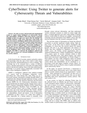
Results Summary:With one exception, the Controlotron meter essentially met its 1% to 2% of rate performanceexpectation for the ‘Field-Installed, Uncalibrated’ meter. The one exception was a case wherethe transducer orientation was clearly not in accordance with the manufacturer’srecommendations for that particular piping arrangement (sensors not located in the plane of thebends).Under good flow profile conditions (meter installation a sufficient distance from distortionelements), the test results show that the Controlotron WideBeam, clamp-on systems meets its0.5% to 1% of rate accuracy specification. The data also show that the repeatability of the meterfell well within the 0.10% of rate specification in all cases; it was within 0.05% in most cases.This implies that even this ‘check-meter’ can be calibrated to each unique piping arrangement toachieve custody transfer performance.Detailed Results:Figure 4 shows the repeatability of the system for five different trials; each at one of threedifferent flow rates for the case where the meter was mounted 23 diameters downstream from asingle elbow. This repeatability was typical for the other cases as well.Typical Repeatability:Single Elbow, 23d0.05002468-0.05Error %-0.1-0.15-0.2-0.25-0.3-0.35Flow Velocity (m/s)Figure 4510121416
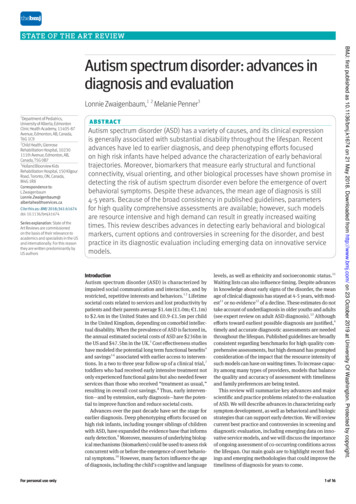
Figure 5 shows results for the Controlotron Meter as a Function of Flow Rate (Average Speed)for Specified Distances Downstream from the Single Elbow, the Double Elbows Out-of-Plane,and the Double Elbows Out-of-Plane with the CPA Flow Conditioner.Impact of Single, Dual and Dual Elbow w/CPA3.0%Percent Error2.0%1.0%5d Dual9d Dual0.0%13d Dual23d Dual44d Dual5d Dual w/CPA024681012149d Dual w/CPA13d Dual w/CPA23d Dual w/CPA44d Dual w/CPA5d Single9d Single13d Single23d Single44d Single-1.0%-2.0%-3.0%-4.0%-5.0%Flow Rate m/sFigure 5This chart shows the exceptional inherent linearity of the meter at each individual distance fromthe various flow profile disturbances. It should be remembered that these curves are generatedfrom an Uncalibrated, Non-linearized flowmeter installed in the field on a facility supplied spoolsection.The individual plots lead us to the following conclusions:a. In all cases without a flow conditioner, when the meter is at least 10 diameters(approx.) downstream from the exit of the elbows, the meter meets its performanceexpectation and shows exceptional inherent linearity and repeatability.b. The worst ‘outlier’ is for the case of 5D downstream from a single elbow that showeda -4% calibration offset (low). This is probably due to a very slow center core flow ifthe flow at this location resembles that measured in the NIST study of the singleelbow effects. Had the meter been oriented such that the sensors transmitted energyin the plane of the bend, we believe this data would have come in within the 1% - 2%of rate performance.6
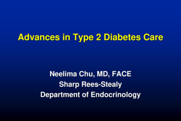
Figure 6 tracks meter accuracy as the meter is moved downstream from the flow profiledistortion elements. Each curve represents a different flow rate and each group of similar curvesrepresents a unique flow profile distortion element configuration. We surmise that the undulatingnature of the swirling flow profile is exposed in Figure 6.Single Bend, Dual Bend, Dual with CPA3.0%2.0%1.0%5 m/s Dual8.5 m/s DualPercent Error0.0%0510152025303540455013 m/s Dual5 m/s Dual w/CPA-1.0%8.5 m/s Dual w/CPA13 m/s Dual w/CPA5 m/s single-2.0%9 m/s single13.5 m/s single-3.0%-4.0%-5.0%Diameters downstream from elbowsFigure 6For the case of the single elbow, it was noted that no attempt was made to position the sonicbeams in the plane of the bend in order to ensure cancellation of cross-flow error. Upon reviewof the tests, it was determined that the flowmeter was installed in an orientation that maximizederror due to cross flow. This is especially evident during the testing done close to the elbow.We expect that proper orientation of meter would have enabled the meter to fully meet itsspecification.For the case of the Dual Elbows, the highly non-linear impact of swirl is evident with distance.This is probably due to the undulating center cone of flow at various positions along the pipe.When the center cone is more compressed or inverted, the meter reads lower. The data showsthis phenomenon to correlate closely with distance. Please note that this is merely speculationand that more detailed studies are suggested.In the case of the Dual Elbow with CPA Plate flow conditioner, we can see that the impact is asimple shift of about 2% in the calibration factor. However, the plate did nothing to mitigatethe variation in calibration along the length of the pipe. Speculation regarding this behavior isprovided below in the section on ‘Flow Conditioners.’7
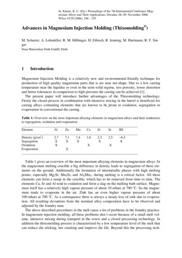
When looking at the graphs, the excellent grouping of results within each flow profile distortionelement type is very apparent. This clearly shows the impact of the flow profile averagingcapability of the WideBeam, Diametric, Reflect-Mode signal injection technique. It implies thatthis technology can be reliably calibrated for a variety of piping configurations and conditionertypes. The important factor in calibrating this unit to a custody transfer performance level is toduplicate the piping configuration. This becomes more evident in the simplified Figure 7.Figure 7 restates the data from Figure 5, however the results obtained with the CPA plate andthe results obtained at meter location 5d from the single elbow are removed.Single & Dual Elbow; Single 5D removed, No CPA1.5%1.0%0.5%0.0%Percent Error02468-0.5%-1.0%-1.5%1012145d Dual9d Dual13d Dual23d Dual44d Dual9d Single13d Single23d Single44d Single-2.0%-2.5%-3.0%Flow Rate (m/s)Figure 7For reasons which will be explained below, the use of a CPA Flow Conditioner or similar typeelements may not be ideal for Controlotron’s WideBeam, Diametric flow measurementtechnology – unless meter calibration is specifically adjusted for that particular conditioner. Inaddition, the one set of data for the single elbow case at 5D from the elbow has been eliminatedas this is considered a misapplication of the product due to incorrect meter orientation.Transducers should have been mounted at 3 o’clock and 9 o’clock when located very close to ahorizontal elbow.This Figure shows that the ‘out of box,’ uncalibrated meter, basically met its specification evenunder extraordinary conditions of swirl and crossflow without factory fine-tuning. The only twocurves outside of the 2% band were for 5D and 13D away from a double elbow. Yet, thesecurves were still within 2.5%.8
Practical Meaning of Data:The data presented show that the WideBeam, Reflect-Mode mounting technology providesexcellent flow profile averaging and is highly tolerant of crossflow and swirl. This field clampon meter can be used with a high degree of confidence that it will meet its accuracy specificationeven under conditions of significant flow profile distortion.The data also imply that this technology can be calibrated to specific piping configurations withdistorted flow profiles, due to its excellent repeatability. In addition, since known pipingconfigurations have been shown to have predictable flow profile impact (refer to NIST papermentioned on page 2), it is possible to specifically program a flowmeter for these pipingconditions. In other words, if a pre-calibrated, flowmeter (i.e. within 0.25%) is intended to beused at 10D from a single elbow or 8D from a double elbow, for example, a calibration factorcan be determined from theoretical and historical data that will optimize accuracy for thatapplication. This is made possible by the extremely good flow profile averaging offered byWideBeam systems in Reflect-Mode mounting.A Word About Flow Conditioning:Most flow conditioners for ultrasonic flow meters have been designed to restore a conical,symmetric flow profile. This is required for optimal performance of insert-type, chordalultrasonic flow meters. Insert chordal type meters are impacted less by Reynolds number effectsbecause they have the ability to measure the shape of the flow profile and compute a weightedaverage. The challenge when using diametral or clamp-on flowmeters with this type of flowconditioner is that the conical profile may not reflect the shape of the flow profile normallyassociated with the viscosity, flow rate, and pipe characteristics of the application. In otherwords, while these types of flow conditioners do a good job of straightening out the flow, theymay produce a flow profile that would normally be associated with a different ReynoldsNumber. The result is a false or forced Reynolds number for that particular flow rate.A diametral system relies on the predictable nature of flowrate and Reynolds Number, and it hasno means of determining the Reynolds Number through path analysis since all paths go throughthe center of the flow stream. Therefore, if the shape of the flow represents an artificial Nre – notpredicted from the flow rate, viscosity and pipe conditions, an incorrect Nre Compensation valuewill be used and the meter may show errors. The flow conditioner adds an element for whichthere is typically no compensation. However, it is certainly possible to calibrate the meterspecifically for any individual flow conditioner.WideBeam, Reflect-Mode systems do such a good job of flow profile averaging that the impactof flow profile distortion is inherently minimized, and making the flow more symmetric orconical is not crucial. (Proper meter orientation is assumed for crossflow applications.)Controlotron recommends a different type of flow conditioner. WideBeam, Reflect-Modetechnology benefits from a conditioner that compresses or flattens the flow profile. This servesto reduce the criticality of the Reynolds Number Compensation and makes the meter moreimmune to changes in viscosity of the liquid or gas. (Note: Controlotron offers viscositytracking software to deal with viscosity changes in liquids.) Controlotron manufacturers avariety of flow-flattening type flow conditioners. This device is essentially an aggressivereducer that serves to mix the flow and flatten the profile. The result is a dynamic expansion ofthe ‘flat’ area of the Reynolds Number Compensation curve.9
Although extensive testing on Gas applications has not yet been accomplished with various flowconditioners, Controlotron does have experience with flow flattening elements for liquidapplications. These seem to bear out the theory, and we see no reason why this should not carryover to gas applications.When a flow conditioner is used with a WideBeam system – or any diametral flowmeter –calibration must be done either with the conditioner in place or with the known impact of theconditioner accounted for in the programming of the flowmeter.It is our expectation that if an aggressive concentric reducer type of flow conditioner was used asthe conditioner, the data would have shown markedly less of the characteristic non-linearity withdistance caused by the double elbow. There still would have been some calibration shift, ofcourse, but the shape of these curves (Figure 6) would have been much more flat and the rangeof calibration factors (Figure 5) would have been more compressed. To repeat, when using anyflow conditioner with a diametral system, the system must be calibrated to that conditioner.It should also be noted that the proper position for such a flow-flattening conditioner would bevery close to the inlet of the flowmeter. Controlotron actually offers its Profiler conditioningelement built in to the spool itself. This is due to the limited range of the flattening effect as flowquickly regains its characteristic conical shape.It is hoped that further testing of flow conditioners with WideBeam technology can be done inthe next few months.Conclusion:The most important aspect of a flowmeter is its ability to meet its specification – whatever thatspecification may be. This test exercised a field-clamp-on meter over a wide range ofinstallation and flow profile conditions. The instrument not only met its specified accuracy andrepeatability range, but it exposed the potential of the technology to achieve custody transferaccuracy in its pre-calibrated spool configuration.10
NOTEA special thanks to Dr. George Mattingly of NIST for his technical assistance inreviewing and interpreting some of the data in this paper.Addendum:Photos of the Test:Single ElbowDual Elbow11
Other Test Site Photos12
References[1] Paper presented at the North Sea Flow Measurement Workshop, a workshoparranged by NFOGM & TUV-NELNote that this reference was not part of the original paper, but has been addedsubsequently to make the paper searchable in Google Scholar.
results for the Controlotron WideBeam system. Controlotron WideBeam technology uses sound that passes diametrically through the fluid – not in chordal mode, as is the case for most insertion type meters. Consequently, meter behavior is expected to be quite different from other ultrasonic


