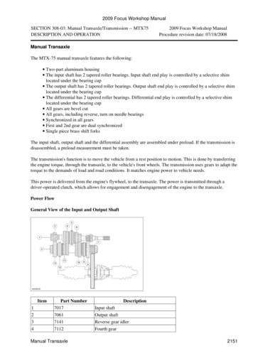
Transcription
«Escort 1991/1996 Table of Contents»«Group 16: Manual Transmission and Clutch»«Section 16-03: MTX 75 Manual Transmission and Clutch»«REMOVAL AND INSTALLATION»MTX 75 Transmission - Dismantle and Assemble (16 118 8)(transmission removed)Special Tools14-010Installer, bearing cups14-011Installer, selector shaft oil seal14-024Installer, bearing rings15-026A-01Thrust pad15-032Installer, differential bearing15-036Installer, bearing rings15-041Preload gauge15-048-01Adaptor15-048Remover, bearing rings15-050ARemover, taper roller bearing (basic tool)15-053Slide hammer15-058Installer, differential oil seal
15-073Socket15-074Remover, bearing rings16-019Remover/installer, selector shaft oil seal16-058Mounting plate, transmission16-059Measuring fixture, end float output shaft16-060Collet for 15-050A16-061Collet for 15-050A16-062Collet for 15-050A16-063Pressure plate, gear wheel removal16-074Remover, driveshaft oil seal21-024-02Adaptor for 21-02421-024-07Adaptor for 21-02421-024Valve spring compressor21-031 BMounting bracket, transmission21-103ARemover/installer, selector shaft ball sleevesProprietary Tools ƒƒƒƒƒƒƒƒƒø Magnetic fixture ƒƒƒƒƒƒƒƒƒ Dial gauge ƒƒƒƒƒƒƒƒƒ Hot air fan ƒƒƒƒƒƒƒƒƒƒŸWorkshop Equipment
ƒƒƒƒƒƒƒƒƒƒƒƒƒƒƒƒ ƒƒƒƒƒƒƒƒƒƒƒƒƒƒƒƒø Press ƒƒƒƒƒƒƒƒƒŸMaterials ƒƒƒƒƒƒƒƒƒƒƒƒƒƒƒƒ ƒƒƒƒƒƒƒƒƒƒƒƒƒƒƒƒø High-temperature grease ESD-M1C220-A ƒƒƒƒƒƒƒƒƒƒƒƒƒƒƒƒ ƒƒƒƒƒƒƒƒƒƒƒƒƒƒƒƒ Sealer WSK-M2G348-A5 ƒƒƒƒƒƒƒƒƒƒƒƒƒƒƒƒ ƒƒƒƒƒƒƒƒƒƒƒƒƒƒƒƒ Transmission fluid (ATF) ESD-M2C186-A ƒƒƒƒƒƒƒƒƒƒƒƒƒƒƒƒ ƒƒƒƒƒƒƒƒƒƒƒƒƒƒƒƒ Freezing spray ƒƒƒƒƒƒƒƒƒŸMeasuring and Adjusting Shims ƒƒƒƒƒƒƒƒƒƒƒƒƒƒƒƒƒ ƒƒƒƒƒƒƒƒƒƒƒƒƒƒƒƒƒƒƒƒƒƒ ƒƒƒƒƒƒƒƒƒƒƒƒƒƒƒƒƒƒƒƒƒƒ ƒƒƒƒƒƒƒƒƒƒƒƒƒƒƒƒƒƒƒƒƒƒ Input Shaft Output Shaft Differential ƒƒƒƒƒƒƒƒƒƒƒƒƒƒƒƒƒ ƒƒƒƒƒƒƒƒƒƒƒƒƒƒƒƒƒƒƒƒƒƒ ƒƒƒƒƒƒƒƒƒƒƒƒƒƒƒƒƒƒƒƒƒƒ ƒƒƒƒƒƒƒƒƒƒƒƒƒƒƒƒƒƒƒƒƒƒ Measuring shim in mm 1,00 1,00 1,10 ƒƒƒƒƒƒƒƒƒƒƒƒƒƒƒƒƒ ƒƒƒƒƒƒƒƒƒƒƒƒƒƒƒƒƒƒƒƒƒƒ ƒƒƒƒƒƒƒƒƒƒƒƒƒƒƒƒƒƒƒƒƒƒ ƒƒƒƒƒƒƒƒƒƒƒƒƒƒƒƒƒƒƒƒƒƒ Adjustment shim availability (mm) 1,15 - 1,71 1,31 - 1,91 1,40 -- ƒƒƒƒƒƒƒƒƒƒƒƒƒƒTransmission - Dismantleµ1.Detach the clutch release lever.12µ2.Undo the bolt and pull off the lever.Withdraw the gaiter and the bearing bush from above.Fit Special Tools.
µ3.Remove the selector mechanism.zzzPut the transmission in neutral.Undo the six bolts.Remove the complete selector mechanism assembly.µ4.Remove the thrust bearing and the release shaft.µ5.Remove the guide sleeve.12Undo the three bolts.Twist the guide sleeve and prise off.
µ6.Remove the driveshaft oil seals with the Special Tool.µ7.Detach the speedometer drive pinion.12Pull out the roll pin.Pull out of drive pinion.Detach the selector shaft oil seal.µ8.Pull off the oil seal using the special tool.
µNote:Do not drive out the dowel pins.9.Remove the transmission housing bolts.µCAUTION:Do not damage the transmission housing.10. Separate the transmission housing halves12µ11.Use a support.Separate the housing sections using two levers positioned opposite each other.Remove the differential.
12µ12.Remove the first/second gear selector rods and selector fork.12µ13.14.Remove the selector rods.Remove the first/second gear selector fork.Remove the first/second gear selector forks.12zµLift out the complete differential assembly.Take out the magnetic disc.Swivel the fifth/reverse gear selector fork to one side.Turn the third/fourth gear selector fork and remove it.Remove the fifth/reverse gear selector fork.Remove the reverse gear idler.
1 Detach the circlip.Tilt the input and output shafts to the side.2 Remove the reverse gear idler by pulling it upwards (see following step for removal sequence).µ15.Removal sequence for removing the reverse gear idler.12345µ16.CirclipUpper thrust washerReverse gear idlerNeedle roller bearingLower thrust washerRemove the input and output shafts.zzLift the input and output shafts together out of the transmission housing.Take out the mounting block and reverse idler gear together with the needle roller bearing andthrust washers.
µ17.Remove the selector shaft.12Undo the ball socket and take off the selector shaft.Pull off the selector shaft.µ18.Remove the selector shaft ball sleeves.µ19.Remove the inner selector shaft bearing bush.
Remove the bearing rings.µNote:Fit the special tool in the transmission recesses.20. Take off the differential bearing ring.µNote:Fit the special tool in the transmission recesses.21. Remove the bearings rings from the input and output shafts.Note:Fit the special tool in the transmission recesses.
µ22.Remove the differential and the bearing rings.zzFrom the input shaftFrom the differentialµNote:Fit the special tool in the transmission recesses.23. Remove the input shaft bearing ring and the shim.µNote:Only carry out if there is damage or leaks.24. Remove the reverse gear idler shaft.
µNote:See previous step.25. Drive out the reverse gear idler shaft with a block of hardwood.Dismantle the differential.µ26.Pull the taper roller bearing off the differential.1 Insert the thrust pad.2 Pull off the taper roller bearing.Detach the speedometer worm gear.µ27.Detach the crown wheel.Note:Use a copper hammer.Unscrew the retaining bolts and separate the crown wheel from the differential cage by tappinglightly.28.General note.Note:From model year '95 a double synchroniser is installed for 1st, 2nd and 3rd gears. The layout andassembly of the single synchroniser for third gear is identical to that for fourth gear. The stepsdescribed below refer to the double synchroniser. Refer to the Technical Data table for renewal ofsynchroniser parts.
CAUTION:The inner synchroniser ring and the synchroniser cone must be handled with great care.The layout and assembly of the single synchroniser for 3rd gear is identical to that for 4th gear. Thesteps described below refer to the double synchroniser. Refer to the Technical Data table forrenewal of synchroniser parts.Layout of the input shaft ƒƒƒƒƒƒƒƒƒƒƒƒƒƒƒ ƒƒƒƒƒƒƒƒƒƒƒƒƒƒƒƒƒø Item Description ƒƒƒƒƒƒƒƒƒƒƒƒƒƒƒ ƒƒƒƒƒƒƒƒƒƒƒƒƒƒƒƒƒ 1 Taper roller bearing on the clutch side. ƒƒƒƒƒƒƒƒƒƒƒƒƒƒƒ ƒƒƒƒƒƒƒƒƒƒƒƒƒƒƒƒƒ 2 Input shaft ƒƒƒƒƒƒƒƒƒƒƒƒƒƒƒ ƒƒƒƒƒƒƒƒƒƒƒƒƒƒƒƒƒ 3 Needle roller bearing - third gear wheel ƒƒƒƒƒƒƒƒƒƒƒƒƒƒƒ ƒƒƒƒƒƒƒƒƒƒƒƒƒƒƒƒƒ 4 3rd gear wheel ƒƒƒƒƒƒƒƒƒƒƒƒƒƒƒ ƒƒƒƒƒƒƒƒƒƒƒƒƒƒƒƒƒ 5 3rd gear inner synchroniser ring ƒƒƒƒƒƒƒƒƒƒƒƒƒƒƒ ƒƒƒƒƒƒƒƒƒƒƒƒƒƒƒƒƒ 6 3rd gear synchroniser cone ƒƒƒƒƒƒƒƒƒƒƒƒƒƒƒ ƒƒƒƒƒƒƒƒƒƒƒƒƒƒƒƒƒ 7 3rd gear outer synchroniser ring ƒƒƒƒƒƒƒƒƒƒƒƒƒƒƒ ƒƒƒƒƒƒƒƒƒƒƒƒƒƒƒƒƒ 8 3rd/4th gear synchroniser assembly ƒƒƒƒƒƒƒƒƒƒƒƒƒƒƒ ƒƒƒƒƒƒƒƒƒƒƒƒƒƒƒƒƒ 9 Circlip
ƒƒƒƒƒƒƒƒƒƒƒƒƒƒƒ ƒƒƒƒƒƒƒƒƒƒƒƒƒƒƒƒƒ 10 4th gear synchroniser ring ƒƒƒƒƒƒƒƒƒƒƒƒƒƒƒ ƒƒƒƒƒƒƒƒƒƒƒƒƒƒƒƒƒ 11 Needle roller bearing for 4th gear ƒƒƒƒƒƒƒƒƒƒƒƒƒƒƒ ƒƒƒƒƒƒƒƒƒƒƒƒƒƒƒƒƒ 12 4th gear wheel ƒƒƒƒƒƒƒƒƒƒƒƒƒƒƒ ƒƒƒƒƒƒƒƒƒƒƒƒƒƒƒƒƒ 13 5th gear wheel ƒƒƒƒƒƒƒƒƒƒƒƒƒƒƒ ƒƒƒƒƒƒƒƒƒƒƒƒƒƒƒƒƒ 14 Circlip ƒƒƒƒƒƒƒƒƒƒƒƒƒƒƒ ƒƒƒƒƒƒƒƒƒƒƒƒƒƒƒƒƒ 15 Taper roller bearing on the transmission side ƒƒƒƒƒƒƒƒƒŸDismantle input shaftµNote:Taper roller bearing and fifth gear wheel can also be pressed off together (see following step).29. Pull off the taper roller bearing on the transmission side.µ30.Press off the fifth gear wheel together with the taper roller bearing.12Move the circlip upwards out of the annular groove up to the taper roller bearing.Press off the gear wheel together with the circlip and the taper roller bearing.
µ31.Detach the fourth gear wheel together with needle roller bearing and synchroniser ring.123µ32.Gear wheelNeedle roller bearingSynchroniser ringDetach the 3rd/4th gear synchroniser assembly.12CirclipGear synchroniserCAUTION:Carefully pull the selector ring off the gear synchroniser hub; the detent balls arespring-tensioned.
µNote:Mark the installation location of the selector ring.33. Dismantle the gear synchroniser.12345µ34.Detach third gear wheel together with the double synchroniser.12345µSelector ringGear synchroniser hubCompression springBlocker barDetent ballOuter synchroniser ringSynchroniser coneInner synchroniser ringGear wheelNeedle roller bearing35.Pull the taper roller bearing on the clutch side off the input shaft.36.General note.Note:From model year '95 a double synchroniser is installed for 1st, 2nd and 3rd gears. The layout andassembly of the single synchroniser for third gear is identical to that for fourth gear. The stepsdescribed below refer to the double synchroniser. Refer to the Technical Data table for renewal ofsynchroniser parts.
CAUTION:The inner synchroniser ring and the synchroniser cone must be handled with great care.The layout and assembly of the single synchroniser for 3rd gear is identical to that for 4th gear. Thesteps described below refer to the double synchroniser. Refer to the Technical Data table forrenewal of synchroniser parts.Layout of output shaft ƒƒƒƒƒƒƒƒƒƒƒƒƒƒƒ ƒƒƒƒƒƒƒƒƒƒƒƒƒƒƒƒƒø Item Description ƒƒƒƒƒƒƒƒƒƒƒƒƒƒƒ ƒƒƒƒƒƒƒƒƒƒƒƒƒƒƒƒƒ 1 3rd gear wheel ƒƒƒƒƒƒƒƒƒƒƒƒƒƒƒ ƒƒƒƒƒƒƒƒƒƒƒƒƒƒƒƒƒ 2 4th gear wheel ƒƒƒƒƒƒƒƒƒƒƒƒƒƒƒ ƒƒƒƒƒƒƒƒƒƒƒƒƒƒƒƒƒ 3 4th gear needle roller bearing ƒƒƒƒƒƒƒƒƒƒƒƒƒƒƒ ƒƒƒƒƒƒƒƒƒƒƒƒƒƒƒƒƒ 4 5th gear wheel ƒƒƒƒƒƒƒƒƒƒƒƒƒƒƒ ƒƒƒƒƒƒƒƒƒƒƒƒƒƒƒƒƒ 5 5th gear synchroniser ring ƒƒƒƒƒƒƒƒƒƒƒƒƒƒƒ ƒƒƒƒƒƒƒƒƒƒƒƒƒƒƒƒƒ 6 Fifth/reverse gear synchroniser, complete ƒƒƒƒƒƒƒƒƒƒƒƒƒƒƒ ƒƒƒƒƒƒƒƒƒƒƒƒƒƒƒƒƒ 7 Circlip ƒƒƒƒƒƒƒƒƒƒƒƒƒƒƒ ƒƒƒƒƒƒƒƒƒƒƒƒƒƒƒƒƒ 8 Reverse synchroniser ring ƒƒƒƒƒƒƒƒƒƒƒƒƒƒƒ ƒƒƒƒƒƒƒƒƒƒƒƒƒƒƒƒƒ
9 Reverse gear needle roller bearing ƒƒƒƒƒƒƒƒƒƒƒƒƒƒƒ ƒƒƒƒƒƒƒƒƒƒƒƒƒƒƒƒƒ 10 Reverse gearwheel ƒƒƒƒƒƒƒƒƒƒƒƒƒƒƒ ƒƒƒƒƒƒƒƒƒƒƒƒƒƒƒƒƒ 11 Taper roller bearing on the transmission side. ƒƒƒƒƒƒƒƒƒŸDismantle output shaftµNote:Taper roller bearing and reverse gear wheel can also be pressed off together.37. Pull off the taper roller bearing on the transmission side.µ38.Detach the reverse gear wheel.123Gear wheelNeedle roller bearingSynchroniser ring
µ39.Detach the fifth/reverse gear synchroniser, complete.12µ40.CirclipGear synchroniserDetach the fifth gear wheel together with the synchroniser ring and the needle roller bearing.123Synchroniser ringGear wheelNeedle roller bearing
Layout of output shaft ƒƒƒƒƒƒƒƒƒƒƒƒƒƒƒ ƒƒƒƒƒƒƒƒƒƒƒƒƒƒƒƒƒø Item Description ƒƒƒƒƒƒƒƒƒƒƒƒƒƒƒ ƒƒƒƒƒƒƒƒƒƒƒƒƒƒƒƒƒ 1 Output shaft ƒƒƒƒƒƒƒƒƒƒƒƒƒƒƒ ƒƒƒƒƒƒƒƒƒƒƒƒƒƒƒƒƒ 2 2nd gear needle roller bearing ƒƒƒƒƒƒƒƒƒƒƒƒƒƒƒ ƒƒƒƒƒƒƒƒƒƒƒƒƒƒƒƒƒ 3 2nd gear wheel ƒƒƒƒƒƒƒƒƒƒƒƒƒƒƒ ƒƒƒƒƒƒƒƒƒƒƒƒƒƒƒƒƒ 4 2nd gear inner synchroniser ring ƒƒƒƒƒƒƒƒƒƒƒƒƒƒƒ ƒƒƒƒƒƒƒƒƒƒƒƒƒƒƒƒƒ
5 2nd gear synchroniser cone ƒƒƒƒƒƒƒƒƒƒƒƒƒƒƒ ƒƒƒƒƒƒƒƒƒƒƒƒƒƒƒƒƒ 6 2nd gear outer synchroniser ring ƒƒƒƒƒƒƒƒƒƒƒƒƒƒƒ ƒƒƒƒƒƒƒƒƒƒƒƒƒƒƒƒƒ 7 Gear synchroniser assembly (1st/2nd gear) ƒƒƒƒƒƒƒƒƒƒƒƒƒƒƒ ƒƒƒƒƒƒƒƒƒƒƒƒƒƒƒƒƒ 8 Circlip ƒƒƒƒƒƒƒƒƒƒƒƒƒƒƒ ƒƒƒƒƒƒƒƒƒƒƒƒƒƒƒƒƒ 9 1st gear outer synchroniser ring ƒƒƒƒƒƒƒƒƒƒƒƒƒƒƒ ƒƒƒƒƒƒƒƒƒƒƒƒƒƒƒƒƒ 10 1st gear synchroniser cone ƒƒƒƒƒƒƒƒƒƒƒƒƒƒƒ ƒƒƒƒƒƒƒƒƒƒƒƒƒƒƒƒƒ 11 1st gear inner synchroniser ring ƒƒƒƒƒƒƒƒƒƒƒƒƒƒƒ ƒƒƒƒƒƒƒƒƒƒƒƒƒƒƒƒƒ 12 1st gear needle roller bearing ƒƒƒƒƒƒƒƒƒƒƒƒƒƒƒ ƒƒƒƒƒƒƒƒƒƒƒƒƒƒƒƒƒ 13 1st gear wheel ƒƒƒƒƒƒƒƒƒƒƒƒƒƒƒ ƒƒƒƒƒƒƒƒƒƒƒƒƒƒƒƒƒ 14 Output pinion ƒƒƒƒƒƒƒƒƒƒƒƒƒƒƒ ƒƒƒƒƒƒƒƒƒƒƒƒƒƒƒƒƒ 15 Circlip ƒƒƒƒƒƒƒƒƒƒƒƒƒƒƒ ƒƒƒƒƒƒƒƒƒƒƒƒƒƒƒƒƒ 16 Taper roller bearing ƒƒƒƒƒƒƒƒƒŸµ41.Pull off the taper roller bearing on the clutch side.CAUTION:
µMark the output pinion for re-assembly. The output shaft and output pinion are paired and canbe renewed together.42. Press the output pinion and the first gear wheel off together.12µ43.Detach the double synchroniser and the needle roller bearing together.1234µ44.CirclipPinion with first gear wheel.Needle roller bearingInner synchroniser ringSynchroniser coneOuter synchroniser ringRemove the 1st/2nd gear synchroniser, complete.12CirclipGear synchroniser
µ45.Detach the second gear wheel.12345µOuter synchroniser ringSynchroniser coneInner synchroniser ringGear wheelNeedle roller bearingNote:Mark the installation position of the selector ring.46. Dismantle the gear synchroniser.CAUTION:Carefully pull the selector ring off the gear synchroniser hub; the detent balls arespring-tensioned.1 Selector ring2 Gear synchroniser hub3 Compression spring4 Blocker bar5 Detent ballAssemble47.Carefully clean and check all parts before reassembly.
CAUTION:Immerse the double synchronisers transmission fluid (ESD-M2C186-A) and lubricate allmoving parts.µ48.Install the selector shaft ball sleeves.12Insert the inner ball sleeve first.Drive in the ball sleeves using the special tool.µ49.Insert the inner selector shaft bearing sleeve.µ50.Install the selector shaft.1Install the selector shaft.
2µ51.Install the reverse gear idler shaft.123µLocate the ball socket in position and tighten.Apply sealer to the mating face of the reverse gear idler shaft.Locate the reverse gear idler shaft in position with the locating bolt and drive in.Remove the locating bolt and screw in the original bolts.CAUTION:The pressure applied must not exceed 15 kN.52. Install the bearing rings on the transmission housing side.53.z Warm the housing locally with a hot-air blower to about 80ºC.z Cool the bearing rings with a refrigerant spray and insert.z Install the bearing rings using the press:z Input shaft using 15-036z Output shaft using 15-036z Differential using 14-024Shim of required thickness:zzzInput shaft: 1,00 mmOutput shaft: 1,00 mmDifferential: 1,10 mm
µ54.Install the measuring shims and bearing rings from the clutch side of the transmission housing half.zz12Warm the housing locally to about 80ºC.Cool the bearing rings with refrigerant spray.Insert the shims of the required thickness.Insert the bearing rings.CAUTION:The pressure applied must not exceed 15 kN.Note:Install using the press, do not drive it in.Bearing rings from:Input shaft using 14-010Output shaft using 15-036Differential using 14-024Assemble differentialµNote:Do not lubricate taper roller bearings that are to be re-used. New taper roller bearings can be installeduntreated. Carefully clean and check all parts and coat with transmission fluid before assembly.55. Fit the crown wheel to the differential.Tighten the crown wheel evenly, working diagonally.
µNote:The speedometer worm gear or the sensor ring of the vehicle speed sensor must engage in therecess on the housing.56. Press on the taper roller bearing.12µInstall the speedometer worm gear.Press on the taper roller bearing using the press and the Special Tool.CAUTION:Do not use the taper roller bearing as a support.57. Install the taper roller bearing (on the side of the crown wheel).zzSupport the differential below the crown wheel.Press on the taper roller bearing with the special tool.Assemble input shaftNote:Do not oil the taper roller bearing which is being reassembled. New taper roller bearings can beassembled unoiled.58. Carefully clean and check all parts before reassembly. Coat all running parts with transmission fluid(ESD-M2C186-A).Note:From model year '95 a double synchroniser is installed for 1st, 2nd and 3rd gears.
CAUTION:The inner synchroniser ring and the synchroniser cone must be handled with great care.CAUTION:Before installing the double synchroniser unit immerse it in transmission fluid(ESD-M2C186-A).The layout and assembly of the single synchroniser for 3rd gear is identical to that for 4th gear. Thesteps described below refer to the double synchroniser. Refer to the Technical Data table forrenewal of synchroniser parts.Layout of input shaft ƒƒƒƒƒƒƒƒƒƒƒƒƒƒƒ ƒƒƒƒƒƒƒƒƒƒƒƒƒƒƒƒƒø Item Description ƒƒƒƒƒƒƒƒƒƒƒƒƒƒƒ ƒƒƒƒƒƒƒƒƒƒƒƒƒƒƒƒƒ 1 Taper roller bearing ƒƒƒƒƒƒƒƒƒƒƒƒƒƒƒ ƒƒƒƒƒƒƒƒƒƒƒƒƒƒƒƒƒ 2 Input shaft ƒƒƒƒƒƒƒƒƒƒƒƒƒƒƒ ƒƒƒƒƒƒƒƒƒƒƒƒƒƒƒƒƒ 3 3rd gear wheel needle roller bearing ƒƒƒƒƒƒƒƒƒƒƒƒƒƒƒ ƒƒƒƒƒƒƒƒƒƒƒƒƒƒƒƒƒ 4 3rd gear wheel ƒƒƒƒƒƒƒƒƒƒƒƒƒƒƒ ƒƒƒƒƒƒƒƒƒƒƒƒƒƒƒƒƒ 5 3rd inner synchroniser ring ƒƒƒƒƒƒƒƒƒƒƒƒƒƒƒ ƒƒƒƒƒƒƒƒƒƒƒƒƒƒƒƒƒ 6 3rd gear synchroniser cone
ƒƒƒƒƒƒƒƒƒƒƒƒƒƒƒ ƒƒƒƒƒƒƒƒƒƒƒƒƒƒƒƒƒ 7 3rd gear outer synchroniser ring ƒƒƒƒƒƒƒƒƒƒƒƒƒƒƒ ƒƒƒƒƒƒƒƒƒƒƒƒƒƒƒƒƒ 8 3rd/4th gear synchroniser assembly ƒƒƒƒƒƒƒƒƒƒƒƒƒƒƒ ƒƒƒƒƒƒƒƒƒƒƒƒƒƒƒƒƒ 9 Circlip ƒƒƒƒƒƒƒƒƒƒƒƒƒƒƒ ƒƒƒƒƒƒƒƒƒƒƒƒƒƒƒƒƒ 10 4th gear synchroniser ring ƒƒƒƒƒƒƒƒƒƒƒƒƒƒƒ ƒƒƒƒƒƒƒƒƒƒƒƒƒƒƒƒƒ 11 4th gear needle roller bearing ƒƒƒƒƒƒƒƒƒƒƒƒƒƒƒ ƒƒƒƒƒƒƒƒƒƒƒƒƒƒƒƒƒ 12 4th gear wheel ƒƒƒƒƒƒƒƒƒƒƒƒƒƒƒ ƒƒƒƒƒƒƒƒƒƒƒƒƒƒƒƒƒ 13 Fifth gear wheel ƒƒƒƒƒƒƒƒƒƒƒƒƒƒƒ ƒƒƒƒƒƒƒƒƒƒƒƒƒƒƒƒƒ 14 Circlip ƒƒƒƒƒƒƒƒƒƒƒƒƒƒƒ ƒƒƒƒƒƒƒƒƒƒƒƒƒƒƒƒƒ 15 Taper roller bearing ƒƒƒƒƒƒƒƒƒŸµ59.Press on the taper roller bearing on the clutch side.Press on the taper roller bearing using a suitable tube.µNote:See previous step.60. Assemble the third gear wheel.1Needle roller bearing
2345µ61.Assemble the 3rd/4th gear synchroniser.123µ3rd gear wheelInner synchroniser ringSynchroniser coneOuter synchroniser ringInsert the compression springs.Insert the blocker bar, together with the detent balls, next to the spring.Align the selector ring correctly and push it on.Note:Install the synchroniser hub with the large collar facing out and the ring groove facing the small collar.62. Installation position of the third/fourth gear synchroniser.
µ63.Install the third/fourth gear synchroniser.Note:Installation position (see previous step).1 Install the gear synchroniser assembly.2 Fit a new circlip.µ64.Fit the fourth gear wheel.123µ65.Synchroniser ringNeedle roller bearing4th gear wheelPress on the fifth gear wheel.zzPress on the fifth gear wheel using a suitable tube and press.Fit a new circlip.
µ66.Press on the taper roller bearings on the transmission and clutch sides (taper roller bearing on thetransmission side is shown).zPress the taper roller bearing on using a suitable tube.Assemble output shaftNote:Do not lubricate the taper roller bearings which are being reassembled. New taper roller bearings canbe installed unoiled.67. Carefully clean and check all components and coat with transmission fluid (ESD-M2C186-A) beforeassembly.Note:From model year '95 a double synchroniser is installed for 1st, 2nd and 3rd gears.CAUTION:The inner synchroniser ring and the synchroniser cone must be handled with great care.CAUTION:Before installing the double synchroniser unit immerse it in transmission fluid(ESD-M2C186-A).The layout and assembly of the single synchroniser for 3rd gear is identical to that for 4th gear. Thesteps described below refer to the double synchroniser. Refer to the Technical Data table forrenewal of synchroniser parts.
Layout of the output shaft ƒƒƒƒƒƒƒƒƒƒƒƒƒƒƒ ƒƒƒƒƒƒƒƒƒƒƒƒƒƒƒƒƒø Item Description ƒƒƒƒƒƒƒƒƒƒƒƒƒƒƒ ƒƒƒƒƒƒƒƒƒƒƒƒƒƒƒƒƒ 1 Output shaft ƒƒƒƒƒƒƒƒƒƒƒƒƒƒƒ ƒƒƒƒƒƒƒƒƒƒƒƒƒƒƒƒƒ 2 2nd gear needle roller bearing ƒƒƒƒƒƒƒƒƒƒƒƒƒƒƒ ƒƒƒƒƒƒƒƒƒƒƒƒƒƒƒƒƒ 3 2nd gear wheel ƒƒƒƒƒƒƒƒƒƒƒƒƒƒƒ ƒƒƒƒƒƒƒƒƒƒƒƒƒƒƒƒƒ 4 2nd gear inner synchroniser ring ƒƒƒƒƒƒƒƒƒƒƒƒƒƒƒ ƒƒƒƒƒƒƒƒƒƒƒƒƒƒƒƒƒ
5 2nd gear synchroniser cone ƒƒƒƒƒƒƒƒƒƒƒƒƒƒƒ ƒƒƒƒƒƒƒƒƒƒƒƒƒƒƒƒƒ 6 2nd gear outer synchroniser ring ƒƒƒƒƒƒƒƒƒƒƒƒƒƒƒ ƒƒƒƒƒƒƒƒƒƒƒƒƒƒƒƒƒ 7 1st/2nd gear synchroniser assembly ƒƒƒƒƒƒƒƒƒƒƒƒƒƒƒ ƒƒƒƒƒƒƒƒƒƒƒƒƒƒƒƒƒ 8 Circlip ƒƒƒƒƒƒƒƒƒƒƒƒƒƒƒ ƒƒƒƒƒƒƒƒƒƒƒƒƒƒƒƒƒ 9 1st gear outer synchroniser ring ƒƒƒƒƒƒƒƒƒƒƒƒƒƒƒ ƒƒƒƒƒƒƒƒƒƒƒƒƒƒƒƒƒ 10 1st gear synchroniser cone ƒƒƒƒƒƒƒƒƒƒƒƒƒƒƒ ƒƒƒƒƒƒƒƒƒƒƒƒƒƒƒƒƒ 11 1st gear inner synchroniser ring ƒƒƒƒƒƒƒƒƒƒƒƒƒƒƒ ƒƒƒƒƒƒƒƒƒƒƒƒƒƒƒƒƒ 12 1st gear needle roller bearing ƒƒƒƒƒƒƒƒƒƒƒƒƒƒƒ ƒƒƒƒƒƒƒƒƒƒƒƒƒƒƒƒƒ 13 1st gear wheel ƒƒƒƒƒƒƒƒƒƒƒƒƒƒƒ ƒƒƒƒƒƒƒƒƒƒƒƒƒƒƒƒƒ 14 Output pinion ƒƒƒƒƒƒƒƒƒƒƒƒƒƒƒ ƒƒƒƒƒƒƒƒƒƒƒƒƒƒƒƒƒ 15 Circlip ƒƒƒƒƒƒƒƒƒƒƒƒƒƒƒ ƒƒƒƒƒƒƒƒƒƒƒƒƒƒƒƒƒ 16 Taper roller bearing ƒƒƒƒƒƒƒƒƒŸµNote:See the following step.68. Assemble the second gear wheel.12345Needle roller bearing2nd gear wheelInner synchroniser ringSynchroniser coneOuter synchroniser ring
µNote:Mark the installation position69. Assemble the 1st/2nd gear synchroniser.123µInsert the compression springs.Fit the blocker bar and the gear synchroniser hub ball detents next to the spring.Align the selector ring correctly and push it on.Note:The small collar on the gear synchroniser hub must point outwards.70. Installation position of the first/second gear synchroniser.
µNote:Installation position (see previous step)71. Assemble the 1st/2nd gear synchroniser.12µNote:See previous step.72. Assemble first gear wheel with double synchroniser.12345µInstall the gear synchroniser assembly.Fit a new circlip.Outer synchroniser ringSynchroniser coneInner synchroniser ring1st gear wheelNeedle roller bearingCAUTION:The output pinion can only be placed on the splines in one position.73. Press on the output pinion.12zPress on the output pinion using a suitable tube and press.Fit a new circlip.Fit the output pinion with the mark facing upwards.
µ74.Press on the taper roller bearing.Press on the taper roller bearing using a suitable tube and press.Layout of the output shaft ƒƒƒƒƒƒƒƒƒƒƒƒƒƒƒ ƒƒƒƒƒƒƒƒƒƒƒƒƒƒƒƒƒø Item Description ƒƒƒƒƒƒƒƒƒƒƒƒƒƒƒ ƒƒƒƒƒƒƒƒƒƒƒƒƒƒƒƒƒ 1 3rd gear wheel ƒƒƒƒƒƒƒƒƒƒƒƒƒƒƒ ƒƒƒƒƒƒƒƒƒƒƒƒƒƒƒƒƒ 2 3rd gear wheel ƒƒƒƒƒƒƒƒƒƒƒƒƒƒƒ ƒƒƒƒƒƒƒƒƒƒƒƒƒƒƒƒƒ 3 5th gear wheel ƒƒƒƒƒƒƒƒƒƒƒƒƒƒƒ ƒƒƒƒƒƒƒƒƒƒƒƒƒƒƒƒƒ 4 5th gear wheel
ƒƒƒƒƒƒƒƒƒƒƒƒƒƒƒ ƒƒƒƒƒƒƒƒƒƒƒƒƒƒƒƒƒ 5 5th gear synchroniser ring ƒƒƒƒƒƒƒƒƒƒƒƒƒƒƒ ƒƒƒƒƒƒƒƒƒƒƒƒƒƒƒƒƒ 6 Gear synchroniser, complete - (fifth/reverse gear) ƒƒƒƒƒƒƒƒƒƒƒƒƒƒƒ ƒƒƒƒƒƒƒƒƒƒƒƒƒƒƒƒƒ 7 Circlip ƒƒƒƒƒƒƒƒƒƒƒƒƒƒƒ ƒƒƒƒƒƒƒƒƒƒƒƒƒƒƒƒƒ 8 Synchroniser ring - reverse gear ƒƒƒƒƒƒƒƒƒƒƒƒƒƒƒ ƒƒƒƒƒƒƒƒƒƒƒƒƒƒƒƒƒ 9 Needle roller bearing - reverse gear ƒƒƒƒƒƒƒƒƒƒƒƒƒƒƒ ƒƒƒƒƒƒƒƒƒƒƒƒƒƒƒƒƒ 10 Reverse gearwheel ƒƒƒƒƒƒƒƒƒƒƒƒƒƒƒ ƒƒƒƒƒƒƒƒƒƒƒƒƒƒƒƒƒ 11 Taper roller bearing ƒƒƒƒƒƒƒƒƒŸµ75.Fit the fifth gear wheel together with the synchroniser ring and needle roller bearing.123µNeedle roller bearing5th gear wheelSynchroniser ringNote:Mark the installation position76. Assemble the fifth/reverse gear synchroniser.123Insert the compression springs.Fit the blocker bar and the detent balls next to the spring.Align the selector ring correctly and push it on.
µNote:Install the gear synchroniser hub with the small collar and the ring groove pointing outwards.77. Installation position of gear synchroniser.µNote:Install the gear synchroniser hub with the small collar and the ring groove pointing outwards.78. Fit the fifth/reverse gear synchroniser.12µ79.Install the gear synchroniser assembly.Attach a new circlip.Assemble the reverse gear wheel.
123µ80.Synchroniser ringNeedle roller bearingReverse gearwheelPress on the taper roller bearing.Press on the taper roller bearing using a suitable tube and press.Measure the shims.µNote:Do not lubricate taper roller bearings that are to be re-used. Fit new taper roller bearings untreated.81. Insert the input and output shafts into the transmission housing.zzEngage 4th gear.Put the input and output shafts together and insert them in the transmission housing.
µNote:Do not lubricate taper roller bearings that are to be re-used. Fit new taper roller bearings untreated.82. Install the differential.µNote:The mating face must be scrupulously clean.83. Fit the housing sections on the clutch side.Fit the special tool and the longer bolt.µ84.Assemble the transmission housing sections on the clutch side.Tighten the 16 flange bolts evenly.
µ85.Attach the special tool.Fit the measuring bar to the 4th gear wheel.µ86.Prepare the input shaft for measurement.Turn the input shaft back and forth about 20 times so that the bearings settle.µ87.Fit the dial gauge.123Fit a steel mounting plate (eg 21-146) to the transmission.Install the magnetic fixture.Set the dial pointer to ”0".
µ88.Measure the input shaft end float.Note:Carry out the measurement preparations and the measurement three times and calculate theaverage value.1 Raise the input shaft using the lever.2 Make a note of the result (eg 0,22 mm).For example: 0,22 mm 0,23 mm 0,21 mm divided by three 0,22 mm.µ89.Prepare the output shaft for measurement.Turn the input shaft back and forth about 20 times so that the bearings settle.µ90.Prepare the output shaft for measurement.
zzµ91.Fit the dial gauge.Set the dial gauge to ”0".Measure the output shaft end float.Note:Carry out the measurement preparations and the measure
MTX 75 Transmission - Dismantle and Assemble (16 118 8) (transmission removed) Special Tools 14-010Installer, bearing cups 14-011Installer, selector shaft oil seal 14-024Installer, bearing rings 15-026A-01Thrust pad 15-032Installer, differential bearing 15-036Installer, bearing rings 15-041Preload gauge 15-048-01Adaptor 15-048Remover, bearing rings 15-050ARemover, taper roller bearing (basic .