Transcription
SP-2000User & ServiceManualSP SERIESCONTINUOUS POWER SYSTEMMODELS COVERED:SP2000SRSP2000SNIncluded with:PIM30 & PIM602000VACLARY CORPORATION150 E. Huntington DriveMonrovia, California 91016Telephone626-359-4486800-44 CLARYFax. 626-305-0254World Wide Web HTTP: // WWW.CLARY.COME-Mail SALES @ CLARY.COMInformation contained herein is the property of Clary Corporation, is proprietary,confidential, and not to be disclosed, disseminated or used except for the purposeprovided byCLARY CORPORATIONP/N 510-13523-REV.B06/29/2010
THE CONTINUOUS POWER COMPANYTABLE OF CONTENTSSection 11.11.21.3Section 22.12.2General DescriptionIntroduction . 5Operating Modes . 6Physical Description . 8General CharacteristicsGeneral Characteristics . 13Specification . 16Section 3Installation and Operations3.13.23.33.4Installation . 19Preparation . 19Procedure . 21Operation Configuration and Setup . 223.53.63.7PIM: Summary of Connectors . 23Operation . 25Optional Communication Procedure . 26Section 44.14.2Section 55.15.25.35.4AdjustmentsAdjustment Overview for DOS Programs . 28Adjustment Overview for Windows Programs . 33Care and MaintenanceSafety . 40Preventive Maintenance . 41Trouble Analysis . 42Service and Repair . 43Warranty . 442
THE CONTINUOUS POWER COMPANYLIST OF FIGURESFigure 1Front Panel View . 8Figure 2Rear Panel View . 10Figure 3PIM To Cabinet Interconnections . 22Figure 4PIM30 & PIM60-Front View . 23Figure 5PIM30 Simplified Schematic Diagram . 24Figure 6PIM60 Simplified Schematic Diagram . 24Figure 7Signal/RS232 Pin Assignments . 27LIST OF TABLESTable 1Front Panel View. 9Table 2Rear Panel View . 10Table 3Electrical Specifications . 16Table 4Physical Specifications, UPS Electronics Module . 17Table 5Physical Specification, PIM Module . 17Table 6Environmental Specifications . 17Table 7Battery Specifications . 17Table 8Clary OutPostTM Batteries* . 18Table 9Recommended Installation Equipment . 20Table 10 Installation Procedure For Traffic UPS . 21Table 11 Preventive Maintenance Schedule . 423
THE CONTINUOUS POWER COMPANY“IMPORTANT SAFETY INSTRUCTIONS”“SAVE THESE INSTRUCTIONS”This manual contains important safety instructions that should be followed duringinstallation and maintenance of the UPS and batteries. The instructions should be followedduring installation and maintenance of the UPS and batteries. Be aware of the followingsymbols and their meaning as they appear throughout the manual:This symbol indicates thatdangerous voltageconstituting a risk ofelectrical shock is presentwithin the unit.!This symbol indicates thatthere are importantoperating andmaintenance instructionsin the literatureaccompanying this unit.CAUTIONRISK OF ELECTRICSHOCK DO NOT OPEN!Earth Ground Symbol:On / Off Symbol:Internal Battery Voltage is 96 VDC.Maximum Ambient Temperature 74 C.This unit intended for installation in a controlled environment (temperature controlled, indoorarea free of conductive contaminants).CAUTION – Do not dispose of batteries in a fire. The batteries may explode.CAUTION - Do not open or mutilate the batteries. Released electrolyte is harmful to theskin and eyes. It may be toxic.CAUTION - A battery can present a risk of electrical shock and high short circuit current.The following precautions should be observed when working on batteries.1. Remove watches, rings, or other metal objects.2. Use tools with insulated handles.FCC-RulesThis equipment generates and uses radio frequency energy and if not installed and used properly in strict accordance with themanufacturer's instructions, may cause interference to radio and television reception. All units in this manual have been testedand found to comply with the limits for a Class A computing device in accordance with the specifications in Subpart J of Part 15of FCC Rules, which are designed to provide reasonable protection against such interference in a commercial installation.However, there is no guarantee that interference will not occur in a particular installation. If this equipment does causeinterference to radio and television reception, which can be determined by turning the equipment off and on, the user isencouraged to try to correct the interference by one or more of the following measures:Reorient the receiving antenna.Relocate the UPS with respect to the receiver.Move the UPS away from the receiver.Plug the UPS into a different outlet so that the UPS and receiver are on different branch circuits.If necessary, the user should consult the dealer or an experienced radio/television technician for additional suggestions. Theuser may find the following booklet prepared by the Federal Communications Commission helpful:"How To Identify and Resolve Radio-TV Interference Problems"This booklet is available from the U.S. Government Printing Office, Washington, DC 20402, Stock No. 004000003454.Page 4
THE CONTINUOUS POWER COMPANYSection 1GENERAL DESCRIPTION1.1INTRODUCTIONYou have selected the highest quality power protection system available for your trafficcontrol devices. You now own a SP Series Traffic UPS (Uninterruptible Power System).The SP Series is an all Digital Technology UPS product designed and manufactured byClary Corporation, the first name in UPS reliability. Clary UPS can be found on navalwarships and submarines, hospital operating rooms, labs, water treatment plants and trafficintersections. The SP (Signal Power) Series offers a rugged, compact package withsuperior features and performance you can depend on.When power problems occur, there can be no compromising the operations and reliability ofyour traffic control devices - - and no compromising public safety. With fully conditioned,regenerative, sine wave power and military-quality battery backup, the SP Series TrafficUPS is your complete power solution.This Owner’s Operating Manual is provided with your new SP Series Traffic UPS. It willenhance your understanding of the product and its functions.WE STRONGLY URGE YOU TO READ THIS MANUAL COMPLETELY, PRIOR TOBEGINNING INSTALLATION OR ATTEMPTING OPERATION.Studying this manual will save you time and effort in your installation and application, and itwill assure a trouble free installation and startup session, thus enhancing public safety andthe image of your agency.The illustrations provided will familiarize you with this product’s operating modes andcomponents. Always operate the unit within the guidelines and specifications provided tomaximize safety and the lifetime of the unit. Your understanding of the product is a keyelement in assuring the proper use and effectiveness of the SP Series Traffic UPS.Page 5
THE CONTINUOUS POWER COMPANY1.2 OPERATING MODESClary’s SP Series Uninterruptible Power Systems (UPS) are designed for powering traffic &pedestrian indications, plus critical traffic control devices (i.e., controllers, modems, CMU’s,etc.). The power system consists of three elements, which work together to provide criticalloads with continuous, conditioned, regulated, sinusoidal waveform power that is free fromdisturbances such as spikes, surges, brownouts or blackouts. These elements are the:1. UPS Module – (UPS)2. Power Interface Module - (PIM)3. Battery ModuleBackup power is achieved with a set of rechargeable, SVRLA (sealed valve-regulated leadacid), maintenance-free, AGM (absorbed glass mat), batteries. The complete UPS systemis controlled by an onboard digital microprocessor at all times.There are two basic modes of operation: Standby Operating ModeContinuous Operating ModeIn both modes, the UPS continuously generates 120V AC power. The selected modedetermines when and how the UPS generated power is applied to the loads in the trafficcabinet.Standby Operating Mode:During Standby operation, utility (AC) power enters the PIM and passes through a normallyclosed contactor then directly out to the cabinet power bus, PDA, etc. This utility power isused to power the intersection until a power disturbance occurs at which time, the contactoris switched, routing the UPS generated AC power to the cabinet power bus. Typically, theUPS will then be drawing its power from the battery pack. This operation continues untilgood utility power is restored, after which, the contactors switch back to route the utilitypower to the loads.With Standby operation, 0.5 seconds (user programmable from 30ms to 2.5sec) after anoutage is detected, standby power is connected to the system and if desired, the FlashCommand is initiated, forcing the cabinet into Flash Mode operation. Depending on the sizeof the battery system being used and the loading on the power system, backup power cancontinue for several hours. Note: If Flash Mode operation is not desired, make sureintersection Load is not over 1400 Watts.When utility power returns, (or upon application of generator power) the SP Series UPSwaits 30 seconds to be sure that the utility power has stabilized. After this built-in safetydelay utility power is restored to the cabinet. The battery charger then recharges thePage 6
THE CONTINUOUS POWER COMPANYbatteries in typically 10 to 20 times (depending on the load) the duration of the outage orbattery discharge time (whichever is shorter).The UPS can be set to force a break in power of 2.5 seconds after utility power returns. Thisis optional (not the default) and is used in intersections when a hard-restart needs to beapplied to various devices when returning from flash.With Standby operation, the ONLY required change to cabinet wiring occurs by theintroduction of the PIM. Removal and Replacement (R&R) of the UPS module is quick andeasy even with traffic control devices (TCD’s) connected to the UPS. If no TCD’s areplugged into the UPS module (i.e. being used for LED flash backup only), R&R of the UPSmodule (for upgrades or in the rare event of UPS failure) can be done without poweringdown the cabinet or otherwise affecting cabinet operation in any way.Continuous Operating Mode:Continuous operation is used for low power applications such as full LED intersections,power to the intersection is continuously conditioned and backed up by the UPS. Within thelimitation of the battery capacity, virtually all brownout and power outages are eliminated.Continuous operation can be used as long as your load does not exceed 1400 Watts.Additional Notes on Operating Modes: A generator can also be connected up and fed through the PIM to provide indefiniteauxiliary backup of the intersection. (OPTIONAL) The SP Series Traffic UPS is designed for compatibility with, and completetransparency to, all traffic signal cabinet functions including police panel operation.Flash Operating Modes:( For PIM 30 Model only)The PIM includes three (3) sets of normally-open (NO) and normally-closed (NC) relay stylecontacts. The contacts are intended to connect to the Flash controllers or other devices inthe traffic cabinet. The contacts are actuated at various times as a means of signaling thesedevices of important aspects of current operation. These three relay contact sets are labeledand switched as follows:LabeledUsage / IndicationNotesOn-BattUPS is operating from battery power.TimerUPS has been on battery longer than programmablethreshold. Used as notice of shutdown coming fromlow-battery cutoff.UPS is operating from battery and the batteryvoltage has fallen below a programmable threshold.Used as notice of shutdown coming from lowbattery cutoff.When unit is in “StandbyOperation”.Default time period is 2 hours.Programmable from 1 to 255minutes.Default voltage is 92V (about40% capacity.)Low-BattPage 7
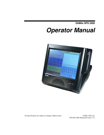
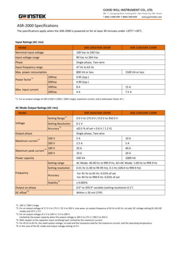
THE CONTINUOUS POWER COMPANY1.3 PHYSICAL DESCRIPTIONThis section will point out and illustrate the various indicators, functions and controls of theSP Series UPS. The important attributes of the SP Series unit are numbered to assist youin locating them on your machine and also to fully explain its function and how it relates tosystem operation.Numbers on the drawing will correspond to the operating component’s name at the bottomwith a brief identification. In the next section, a complete explanation of all numbered itemswill be enhanced to ensure you have a full understanding of the operation of this system.Visual indicators used on the front panel are long lasting, very efficient, light emitting diodes(LED). When operating the push-button switches, always hold the switch in for at least twoseconds to insure function confirmation. This feature has been implemented into the systemdesign to avoid inadvertent operation of any of the user-available functions.Formatted: Font: 11 pt, Not BoldFigure 1Figure 1Figure 1 is the front view of the model SP2000SN. Model SP2000SR isidentical in operation; however, items 17 through 22 have been repositioned to the rearpanel.Formatted: Font: 11 pt, Not BoldTable 1 describes item 1-22.87313496151952122111012141216Figure 1: SP2000SN FRONT PANEL VIEWPage 8172018
THE CONTINUOUS POWER COMPANYTable 1: SP2000SN FRONT PANEL VIEWSP2000SN FRONT PANEL VIEW1SYSTEM POWER SWITCH12HOUR METER – Battery runtime meter inhours2INPUT AC LINE FUSE13EVENT COUNTER– Counts powerinterruptions3INVERTER – Inverter operatingindicator14RESET – Clears Event Counter back tozero4AC IN – Input line indicator15UPS OUTPUT PRESENT – Outputindicator5LOAD LEVEL – Output capacityindicators16DC INPUT– Protection circuit breaker forbattery6BATTERY LEVEL -Charge/discharge indicators17BYPASS – Protection circuit breaker forbypass7COLD START – DC start switch18RS232 – Computer communications signals8COLD START ACKNOWLEDGEINDICATOR19UPS OUTPUT – Continuous powerreceptacle9ALARM – Fault indicator20SIGNAL – Open-collector signal contacts10ALARM SILENT/TEST – Dualfunction switch21AC IN/OUT – Input receptacle for all ACpower(To PIM)11ALARM SILENT/TESTACKNOWLEDGE INDICATOR22DC IN – Input receptacle for all DC power(To Batteries)Page 9
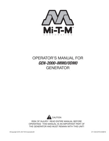
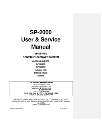
THE CONTINUOUS POWER COMPANY2425191721221518Figure 2: SP2000SR REAR PANEL VIEWTable 2: SP2000SR REAR PANEL VIEWSP2000SR REAR PANEL VIEW232425SYSTEM GROUNDING STUDSNMP – (optional) Slot for sophisticated Network monitoringFAST CHARGER MODULE (optional) Slot for extra charging modulePage 1023
THE CONTINUOUS POWER COMPANYSUMMARY OF INDICATORS AND CONTROLSSYSTEM POWER SWITCH - The main control switch that engages utility power to theentire unit. By activating this switch it initializes normal operation.!NOTE – The DC INPUT circuit breaker must be “ON” before activating theSystem On/Off switch.DC INPUT - A two pole, 30A circuit breaker used to connect the battery to the internal UPSelectronics. It also protects against over-current situations in the battery circuit.INPUT AC LINE FUSE - The input line protection device to limit excessive current draw tothe system.INVERTER - This indicator identifies the status of the regenerated, conditioned protectedoutput power. This indicator will stay ON as long as protected power is available from thepower inverter generator.AC IN - The utility input indicator that identifies status of the line voltage. If the line voltageis within the specified range, it will remain lit. If the AC input is out of range, but present,the indicator will slowly blink.LOAD LEVEL - This is the system output capacity status bar. The number of LEDSilluminated indicates an approximate percentage of system load. All green LEDSilluminated would indicate full load. The top red LED illuminates on over-loads.BATTERY LEVEL - This is the battery status bar graph. During normal operation, this bargraph will show the charging of the battery; all indicators lit will represent a fully chargedbattery. During battery operation, this bar graph represents a discharge meter indicatingless battery time available as each light goes OFF. If Battery status LEDs are blinking, theunit has failed a battery self test. See Trouble Analysis section on page 43 for moreinformation.COLD START - A momentary push-button switch to activate the system in the event noutility power is available. The system will be allowed to start up by using power from thebattery. Depress this switch, the indicator above it will light, and hold it in until the audiblealarm beeps once. The system will maintain a load for a period of time depending upon thecondition of the battery. DC INPUT breaker must be ON.ALARM - This is a fault indicator that will light in the event that the inverter generator is nonoperable. This could be due to an over-temperature situation or an inverter malfunction.Page 11
THE CONTINUOUS POWER COMPANY!NOTE - Cold Start and Alarm Silent switches must be held in for at least twoseconds to engage their function. This is to prevent any inadvertent switchoperation.HOUR METER - A cumulative run time meter that shows the total battery run time for the lifeof the unit.EVENT COUNTER - A meter that counts the number of times the system has gone intobattery operation. The Event Counter also increments each time the unit is turned off andon by the SYSTEM POWER SWITCH.RESET- A momentary pushbutton switch that resets the Event Counter to zero.UPS OUTPUT PRESENT - A green LED that is illuminated to
SP-2000 User & Service Manual SP SERIES CONTINUOUS POWER SYSTEM MODELS COVERED: SP2000SR SP2000SN Included with: PIM30 & PIM60 2000VA Information contained her