Transcription
DRIVER USER MANUALIn accordance with 49 CFR 395.22 (h) In-vehicle informationThis manual must be kept in the vehicle Stoneridge Aftermarket Inc.
ance StatementEZ-ELD Kit ContentsConnector OptionsChanging the connectorInserting the new connectorUsing the extension cableInstallation InstructionsWhat do the EZ-ELD Light and Sound Notifications Mean?How to download the Stoneridge EZ-ELD AppHow to Pair your Smartphone or Tablet with EZ-ELDPairing for the first timeClearing paired information from the EZ-ELD deviceHow to Use Scan and Drive If the device has been previously pairedFirst time pairing using the QR codeUsing the EZ-ELD App for the First TimeDriver LoginHow to Login as a Co-DriverMain Screen71011121315202326262633343435374143462
718192021LogsHow to review logsHow to edit existing ELD recordsHow to manually enter a new recordHow to assign/claim unidentified driver recordsHow to edit and reassign driving time between team driversConfirm or reject edit requestsHow to view Hours of Service violations (HoS warnings)How to certify and send logsHow to view all driver logsUnderstanding event records of logsDOT Roadside InspectionMalfunction and DiagnosisDVIR—Driver-Vehicle Inspection ReportEngine Gauge DashboardMenu SettingsChat/MessagingHow to Log ote: Some screenshots shown in this manual may be different fromwhat you see in the actual App depending on the platform or App versionyou are using. The most up to date version of this manual can bedownloaded from our website at www.EZ-ELD.com.3
GlossaryTermDefinitionData bus (also datadiagnostic bus or CANbus)A means of transmitting data, in this case the linkfrom the ELD to the vehicle’s ECM (engine controlmodule).DOT (Department ofTransportation)The United States governmental department thatregulates transportation (including trucking andcommercial passenger transport).DVIR (Driver VehicleInspection Report)A report a driver is required to prepare at thebeginning and at the end of their working daylisting any maintenance defects found with thevehicle or trailer.ELD (Electronic Logging A device for electronically recording driver logs.Device)This is the new term used in the 2015 DOT rulemandating the use of electronic logs that complywith certain standards.FMCSA (Federal Motor An agency within the DOT that regulates thecommercial transportation industry and tries toCarrier Safetyimprove overall safety.Administration)4
TermDefinitionGPS (GlobalPositioning System)A radio navigation system that allows land, sea,and airborne users to determine their exactlocation, velocity, and time 24 hours a day, in allweather conditions, anywhere in the world.HOS (Hours of Service) A professional driver’s time, as regulated by theDOT. Hours of Service are tracked using a log oftime spent in various statuses: On Duty NotDriving, Driving, Off Duty and Sleeper Berth.Limits are placed on how much time a driver canwork, and how much time he / she must take offto rest.OBD (On-boarddiagnostics)An automotive term referring to a vehicle's selfdiagnostic and reporting capability.Protocols: CAN J1939,ISO15765, J1587,J1708Industry standards for communicating data/information within heavy, medium & light dutyvehicles.RODS (Record of DutyStatus)A log of a driver’s Hours of Service. This may berecorded using a paper log (under certaincircumstances) or electronically using an ELD.5
TermDefinitionScan and DriveTMA Stoneridge trademarked feature which allowsthe driver to very easily pair and connect the EZELD device to their Smartphone in one simplestep.QR CodeA machine-readable code consisting of an array ofblack and white squares, typically used for storingURLs or other information for reading by thecamera on a smartphone.6
1Compliance StatementThis equipment complies with Federal Communications Commission (FCC)and Industry Canada (IC) radiation exposure limits set forth for anuncontrolled environment.This device has been certified as follows:FCC EZ-ELDFCC Caution:Changes or modifications not expressly approved by the party responsiblefor compliance could void the user's authority to operate the equipment.7
FCC Statement:This device complies with Part 15 of the FCC Rules. Operation is subject tothe following two conditions:1.this device may not cause harmful interference, and2.this device must accept any interference received, includinginterference that may cause undesired operation.This equipment has been tested and found to comply with the limits for aClass B digital device, pursuant to part 15 of the FCC Rules. These limits aredesigned to provide reasonable protection against harmful interference in aresidential installation. This equipment generates, uses and can radiateradio frequency energy and, if not installed and used in accordance with theinstructions, may cause harmful interference to radio communications.However, there is no guarantee that interference will not occur in aparticular installation. If this equipment does cause harmful interference toradio or television reception, which can be determined by turning theequipment off and on, the user is encouraged to try to correct theinterference by one or more of the following measures: Reorient or relocate the receiving antenna. Increase the separation between the equipment and receiver. Connect the equipment into an outlet on a circuit different from that towhich the receiver is connected. Consult the dealer or an experienced radio/TV technician for help.8
RSS-Gen & RSS-247 statement:This device complies with Industry Canada licence-exempt RSS standard(s).Operation is subject to the following two conditions:1. this device may not cause interference, and2. this device must accept any interference, including interference thatmay cause undesired operation of the device.Le présent appareil est conforme aux CNR d'Industrie Canada applicablesaux appareils radio exempts de licence. L'exploitation est autorisée aux deuxconditions suivantes :1. l'appareil ne doit pas produire de brouillage, et2. l'utilisateur de l'appareil doit accepter tout brouillage radioélectriquesubi, même si le brouillage est susceptible d'en compromettre lefonctionnement.RSS-102 Statement:This equipment complies with Industry Canada radiation exposure limits setforth for an uncontrolled environment.Cet équipement est conforme à l'exposition aux rayonnements IndustryCanada limites établies pour un environnement non contrôlé.9
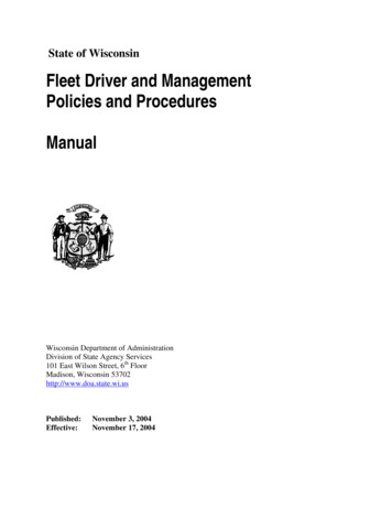
2EZ-ELD Kit Contents EZ-ELD Device with 9 Pin Connector attached 3 Additional On-Board Diagnostic Port (OBD) Connectors with endcaps attached Extension Cable Quick Start Guide Driver User Manual 2 QR Code Stickers Circular Double Sided Adhesive Pad EZ-ELD Device Connector cap when used with the Extension Cable 9 Pin Connector end capWarningDo not use the device while the vehicle is in motion.Mount the device in a fixed position which is visible to thedriver when driving.Always stop the vehicle safely to use the device.Failure to do so may lead to serious injury or death.10
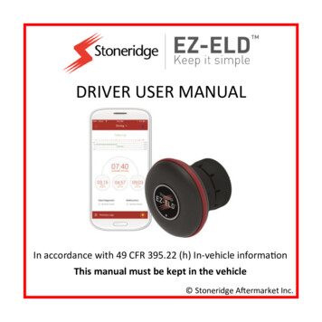
3Connector OptionsThe EZ-ELD is shipped with the 9-pin OBD port connector already fitted. Italso has 3 other connector options included in the kit: 6-pin OBDII Light and Medium Duty Vehicles OBDII for Volvo/Mack heavy duty vehicles6 pin Connector9 pin ConnectorEZ-ELD Devicewith 9 pinConnector(Same for 6 pin)Connector)OBDII Volvo/MackHeavy duty vehicleConnectorOBDII Light andMedium Duty VehiclesConnectorEZ-ELD Device with OBDIIVolvo/Mack Connector(Same for OBDII Light andMedium Duty VehiclesConnector)11
3.1Changing the connectorStep 1Gently pull the rubber lock casings on bothsides of the connector outwards.Here you can see the plastic lock inside eachrubber casing.Step 2Insert a small screwdriver or similar tool intothe gap between the plastic lock and thedevice.Ease the plastic lock out, away from the side ofthe device.Do the same for the lock on the other side too.12
Step 3Once both sides are unlocked, unplug thewhite connector from the main body of thedevice by pushing the small white lever onthe cable connector.3.2Inserting the new connectorIn this example we will insert one of theOBDII connectors.Step 1Remove the cap on the new connector toexpose the wires by pulling out therubber lock cases and plastic locks likeyou did before.13
Step 2Take the small white plug wired into theconnector head and plug it into the back of the EZELD device.Step 3Twist the connector once so the wires wrap tosave space.Step 4Place the connector onto the module, pressing theconnectors gently into place.You will hear two clicks when the locks engage.The connector is now ready to use.14
The connector can be mounted in one of two ways by rotating it 180 .or3.3Using the extension cableIf required due to limited space, the main EZ-ELD device can be mountedaway from the On-board diagnostic port.In this example we will insert one of the OBDII connectors.EZ-ELD main deviceExtension CableAdapter cover(top cover not used inthis example)15
Double sidedAdhesive padOBDII ConnectorStep 1Remove the adaptor cover by following the same process you used beforeto unplug the connector from the EZ-ELD device (see section 3.1).Step 2Connect the end of the extension cablewith the smaller female connector onthe shiny lower adaptor cover.Wrap the wires as before.16
Step 3Connect the other larger connector end ofthe extension cable on the cover for theOBDII or 6-pin/9-pin.Twist the wires around.Step 4Plug the end of the extension cable withthe smaller female connector into the mainconnector of the EZ-ELD device.17
Step 5Carefully position the connector on themodule and press gently until you hear twoclicks.Step 6Plug the other larger end of the extensioncable into the OBDII female connector.Step 7Position the connector on the end cap andpress until you hear two clicks.18
It should look like this - the EZ-ELD device has the long cable extensioncoming from it.Step 8Finally, stick the adhesive pad onto thebottom of the module for mounting in thecab.Remove the backing from the adhesive padand then mount the device in a position ofyour choosing.19
4Installation Instructions1. Find the truck’s diagnostic port. It’s position depends on the vehiclemake and model. You might find the diagnostic port: Under the dash or under the steering column/wheel on the left orright,On the left or right of the pedals, above the pedals,Above the footrest,In the fuse box,Near the handbrake or the clutch pedal handbrake / footbrake.In some cases you may have to remove a plastic cover to find theconnector.Heavy Duty VehiclesDeutsch 6-pinconnectorDeutsch 9-pinconnector20
Light and Medium duty vehiclesOBDII Volvo/Mack Heavy Duty Vehicle ConnectorOBDII Light and Medium Duty Vehicles Connector2. Attach the device to the vehicle’s diagnostic port.In the case of the 9-pin or 6-pin connector,rotate the collar to line up the collar tabs withthe matching slot on the diagnostic port. Pressfirmly until the EZ-ELD device is fullyconnected. Then rotate the collar clockwiseuntil it locks.In the case of the OBDII connector line up theconnector so it exactly matches the diagnostic port in the vehicle. Pressfirmly until the EZ-ELD device is fully connected.Note: During the App set up you will be required to enter the BT PIN code.This can be found on the label on the underside of the EZ-ELD modulebefore you install it, on the QR code sticker or on the label on the back coverof this manual.21
Example of a recommended installation:Example of an unrecommended Installation:Please always install the EZ-ELD device in a place that will not block orinterfere with the safe operation of the vehicle pedals, obstruct the driverin any way or interfere with the safe operation of the vehicle. Please alsoavoid installing the EZ-ELD under metallic surfaces. If space is tight, pleaseuse the extension cable provided in the kit.22
5What do the EZ-ELD Light and SoundNotifications Mean?LED/Buzzer PatternGPSData Bus (Can)Continuous LEDLED LED LED Solid 123blink & blinks 4 blinks blinks blinkssound sounds soundssoundtimes/ x 3x2x1BuzzerNOT OK NOT OKOKOKNOT NOT OK OKOK OKFirst Connection ModulePowered onInitial installation autoset up (90 seconds)Not paired and notconnectedPress the pair button(Green Light—40 sec)Bluetooth ConnectedIOS ConnectedAndroid ConnectedMalfunctionVehicle in motion, drivernot logged inPress and hold buttonappx. 5 secs. Deletepaired BT devices23
Light & Sound PatternDescription2 soundsWhen you attach the device to the vehicle’sdiagnostic port for the first time, the buzzer willsound twice, showing that the device ispowered ON.(Device is powered on)1 sound(Bluetooth paired &connected)3 soundsPress the button once and release, the LED willblink green for about 40 seconds. The buzzerwill sound once, showing that the pairing andconnection were successful. Bluetooth is nowconnected.(Delete paired devices)Press and hold the button on the EZ-ELD devicefor about 5 seconds then release. The buzzerwill sound twice, paired devices have beendeleted.Yellow LEDThe device is not paired and not connected.Green LEDThe device is in pairing mode.Blue LEDBluetooth is connected to an iOS (Apple) device.White LEDBluetooth is connected to an Android device.24
Light and Sound PatternDescriptionRed LED(Blinks four times)Malfunction error detected.Red LED(Continuous blinking/sound)The vehicle is in motion but the driver isnot connected to the EZ-ELD.Red LEDWhenever you attach the device to the(Initial installation auto setup— vehicle’s diagnostic port for the first90 seconds)time, the device will start an auto setupsequence for GPS and data busacquisition.LED blinks three times (yellow,green, white or blue)GPS not working and Data Bus (CAN) notworking.LED blinks twice (yellow, green, GPS OK but Data Bus (CAN) not working.white or blue)LED blinks once (yellow, green,white or blue)GPS not working but Data Bus (CAN) OK.LED solid (yellow, green, whiteor blue)GPS OK and Data Bus (CAN) OK. This isnormal operation.25
6How to download the StoneridgeEZ-ELD AppYou can download the Stoneridge EZ-ELD App for Android and iOS devices.Search for “EZ-ELD” in the Google Play Store for Android phones/tablets, orsearch for “EZ-ELD” in the App Store for iPhones/iPads.Google Play and the Google Play logo aretrademarks of Google Inc.Apple and the Apple logo are trademarks ofApple Inc., registered in the U.S. and othercountries.7How to Pair your Smartphone or Tabletwith EZ-ELD7.1Pairing for the first timeStep 1Once you have downloaded the app from the Google Play orApp Store, launch the EZ-ELD App by tapping the EZ-ELDicon on your phone or tablet.26
Step2Bluetooth will turn on automatically.Step 3Allow the App to access the device.Step 4The LED light on the device should be yellow. This showsthat the EZ-ELD device is not yet paired or connected.Step 5Tap PAIR NEW DEVICE.Step 6Enable GPS if prompted.27
Step 7If you see this screen, please make sure that the EZ–ELD device is connected to the vehicle’s diagnosticport and powered on so it can be found by the App.Step 8The EZ-ELD device will then appear on the screen.Tap to select it.If you have more than one device in range thenplease select the device that you want to pair withby checking the PIN number marked on the EZ-ELDdevice label.28
Step 9You will be prompted to name your EZ-ELD device.This name will be assigned to the EZ-ELD so you caneasily recognize it in future.Step 10Tap on PAIR AND CONNECT.Step 11You will then be prompted to press the EZ-ELDBluetooth control button on the device once(shown on page 30)Step 12After you have pressed the Bluetooth controlbutton once and the LED on the device has turnedgreen then press OK on the App screen.29
Bluetooth Control Button & LED Status IndicatorLocation:The Bluetooth control button allows the pairing ofnew devices to the EZ-ELD (page 26) and also theremoval of all previously paired devices (page 33).The LED status indicator displays basic diagnosticinformation of the EZ-ELD device (page 23).LED Status indicatorBluetooth Control ButtonStep 13In the App, enter the BT PINcode as shown on the labelof the device, on the QRcode sticker or on the labelon the cover of this manual.30
Step 14The buzzer will then sound once, indicating that the pairing was successfuland Bluetooth is now connected.Step 15The LED color will change to white or blue. Blue indicates the phone ortablet you’re using is an iOS (Apple) device and white means you are usingan Android device.Step 16If the VIN number doesn't match your registration youwill be prompted after pairing. If your vehicle is notlisted, please contact your Fleet Manager to create itand add it to your list of authorized vehicles. Tosynchronize with the latest vehicles created in the BackOffice, your Smartphone or Tablet needs to beconnected to the internet.31
Step 17“Device” and “Server Status” are both green. YourEZ-ELD device is connected and working correctly.Device Status: Green – Bluetooth paired andsuccessfully connected.Server Status: Green – You are connected to theEZ-ELD Back office software server.32
7.2Clearing paired information from the EZ-ELD deviceTo delete pairing information from the device and clear all pairing settings:Step 1Make sure the EZ-ELD Device is powered on.Step 2Press and hold down the Bluetooth Control Button on the front of the EZELD device for about 5 seconds.Step 3Release the button.Step 4The buzzer will sound 3 times. This indicates that the paired information hasnow been cleared.Bluetooth control button33
8How to Use Scan and DriveTMAfter initial pairing, Scan and Drive is a time saving feature that allows youto easily and quickly pair and connect the EZ-ELD device with yourSmartphone or tablet.8.1If the device has been previously pairedStep 1Tap on the QR Code imageStep 2Scan the QR Code, holding your phone camerasteady so that the QR Code comes intofocus.34
Step 3The EZ-ELD Device is now paired and connected.Now just log in as normal with your username andpassword.NOTE: To get a new QR Code label for your vehicle contact your FleetManager.8.2First time pairing using the QR CodeStep 1Follow steps 1 and 2 in the previous section.Step 2The App will recognize that you are connecting the EZ-ELD device for thefirst time, and will take you to the next screen “Device Info”.35
Step 3You will be prompted to name your EZ-ELD device.This name will be assigned to the EZ-ELD so you canrecognize it easily in future.Step 4Tap on PAIR AND CONNECT.Step 5Follow the same steps as shown in “How to pair your Smartphone or tabletwith EZ-ELD” (section 7.1.11 to 7.1.17).36
9 Using the EZ-ELD App for the First TimeInvitation EmailThe System Administrator orAuthorized Support Personnel whoadminister the Back Office Systemmust send an ‘Invitation Email’ to eachdriver who works for the company.This is a security measure to ensurethat only authorized drivers are invitedto join the Company’s ELD system.This email contains an invitation key(or unique access code) that the drivermust enter to start the creation oftheir own, unique, user account.37
Step 1Pair and connect the device.Step 2Tap USE INVITATIONStep 3Type or COPY and PASTE the invitation key fromthe Fleet Manager email into the indicated field.Step 4Tap JOIN.38
Step 5Fill in all required fields to register (user name,password, confirm password etc.) and Tap SAVE.NOTE: Your email address must match the oneused in the email invitation from your FleetManager.Step 6To associate a picture with your account, tap onthe camera icon and choose Camera or Gallery.Select your picture.39
Step 7To add an electronic signature, tap SIGNATUREunderneath the “Confirm Password” box.Step 8Use your finger or a stylus to write your signature inthe whit
13 Logs 52 13.1 How to review logs 52 13.2 How to edit existing ELD records 55 13.3 How to manually enter a new record 58 13.4 How to assign/claim unidentified driver records 59 13.5 How to edit and reassign driving time between team drivers 61 13.6 onfirm or reject edit requests 63 13.7 How