Transcription
UM11182Q100 (MC33XS2410) Extreme switch software driver userguideRev. 1.0 — 30 August 2019User manualDocument informationInformationContentKeywordsQ100 eSwitch extreme switchAbstractThis documentation describes how to install and use the Q100 ExtremeSwitch software driver.
UM11182NXP SemiconductorsQ100 (MC33XS2410) Extreme switch software driver user guide1OverviewThis documentation describes how to install and use the Q100 Extreme Switch softwaredriver (driver).The Q100 Extreme Switch software driver encapsulates the functionality of the Q100(MC33XS2410) device. The driver acts as an API layer between the microcontroller lowlevel drivers, e.g. SDK, and the user application, allowing you to perform the following: 2Setting and reading device registers (control and diagnostic bank)Initializing device with default or custom register valuesControlling the OUTx channel by Direct Input or SPI signal, PWM or without PWMReading fault, warning and channel statusMeasurements of voltage, current and temperatureEnabling watchdog, transit to safe modeSetting PWM PI regulationMCU compatibilityThe driver implementation is generic; there is no dependency on a specific MCU.Virtually any MCU with the required peripherals should be able to use the driver.2.1 Peripheral requirementsThe driver needs the following MCU peripherals for its function: SPI Module is required for communication (MOSI M, MISO M, SCLK M, CSB M). GPIO is required for controlling RESET B pin or optionally used for software controlledSPI chip select (CSB M) instead of HW chip select. Interrupt pin is optionally required for use with the FAULT B pin – interruptimplementation is up to user. Timer is optionally required for generating external clock signal for Pulse-WidthModulation (PWM) of the Q100 device - implementation is up to userDepending on the user application, other resources may be required. See the providedexample projects.2.2 Supported devicesQ100 (MC33XS2410) UM11182User manualFour fully-protected 100 mΩ / dual 50 mΩ (at 25 C) high-side switches4 x 1.8 A DC (Pd 2.5 W @ TJ 150 C) or 2 x 3.6 A DC in parallel mode configurationFloating power output architecture to drive all types of loads16-bit SPI port communication 3.3 V / 5.0 V compatible with daisy chain capabilityOutputs controllable via SPI-bus or direct inputsDiagnostic status reported via SPI-busWatchdog for invalid commands or inactive SPI, with programmable timeoutProgrammable interrupt generator that reports to FAULT pin or SPI-busFour independent PWM modules programmable from 0.5 Hz to 2.0 kHzProtection for battery transient overvoltage and reversed polarity battery connectionConfigurable safe modeAll information provided in this document is subject to legal disclaimers.Rev. 1.0 — 30 August 2019 NXP B.V. 2019. All rights reserved.2 / 20
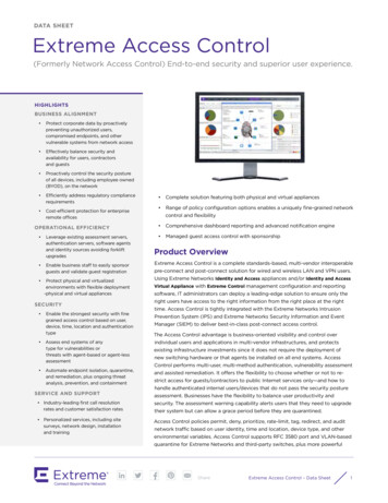
UM11182NXP SemiconductorsQ100 (MC33XS2410) Extreme switch software driver user guide Standby mode with very low power consumption10 mA open load detection in ON stateLatch off with configurable auto retrySevere short-circuit and overload protectionProgrammable active current limit threshold to minimize short-circuit effect12 bits ADC:– Current from 5.0 mA to 5.0 A with 3 % above 100 mA, 4.0 mA at 10 mA– Voltage from 0.5 to 65 V with 5 % above 5.0 V– Temperature warning for each channel plus central die monitoring Qualified in accordance with AEC Q100 grade 1 Electrical transient disturbance immunity according of ISO 7637-2 and ISO 16750-22.3 Supported MCUsThe current implementation of the Q100 software driver is generic, such that any suitable32 b microcontroller with SPI module and other necessary peripheries can be used. Seechapter Section 2.1 "Peripheral requirements" for peripheral requirements.Board nameMCU BoardDescriptionFRDM-XS2410EVB FRDM-KL25ZQ100 board with FRDM-KL25FRDM-XS2410EVB S32K144EVB-Q100Q100 board with S32K144EVBThe driver was tested with an S32K144 MCU and S32K14x EAR SDK 0.8.6. Figure 1shows a HW setup of S32K144EVB-Q100 and Q100 EVB.The FRDM-XS2410EVB (Q100) evaluation board is directly compatible with the FRDMKL25Z board. See Table 1 for used pin compatibility between FRDM-XS2410EVB (Q100)evaluation board and S32K144EVB-Q100 and FRDM KL25Z.Table 1. Q100 EVB pin compatibility with S32K144EVB-Q100Pin Function(Q100 EVB)MOSIMISOCLKCSRST BFAULT BLHMIN1IN2IN3IN4S32K144EVB-Q100 RDM 2When other MCU boards or other Q100 EVB are used, refer to the provided user guidesand schematics of the respective boards.UM11182User manualAll information provided in this document is subject to legal disclaimers.Rev. 1.0 — 30 August 2019 NXP B.V. 2019. All rights reserved.3 / 20
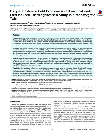
UM11182NXP SemiconductorsQ100 (MC33XS2410) Extreme switch software driver user guideFigure 1. Set of S32K144 and FRDM-XS2410EVB (Q100) evaluation boards3Q100 Extreme switch software driverThis section provides an overview of the functionality, settings and usage of the driver(configuration and functions). For additional information, see the API Programmer'sGuide (included in the Q100 software driver zip file) and the comments embedded in thecode.The MSDI software driver consists of three files. The main functionality is contained inQ100.c and Q100.h whereas Q100 regmap.h contains register map of device. As thedriver is not platform specific, several functions (marked as externalin Q100.h) need to beimplemented by the user.3.1 Configuring the driverThe configuration structure shown in Figure 2 is the user interface available forconfiguring the driver and its behavior. The user must set appropriate Q100 devicetype and instance of the driver (in case more instances will be used) into the driverconfiguration structure (Q100 driver t). The driver configuration structure is passed to allAPI functions of the driver as a parameter. Members qSpiStatus, regMap and toggleBitare initialized automatically in the Q100 Init function.As the driver is not platform specific, the user needs to implement several low-levelfunctions. See Section 3.2 "Driver API". Instance member in Q100 driver t structureis not modified by the driver itself. This member is passed to user-defined functions inorder to differentiate between Q100 driver instances in case that more Q100 devices areconnected to the MCU.Figure 2. Driver configurationUM11182User manualAll information provided in this document is subject to legal disclaimers.Rev. 1.0 — 30 August 2019 NXP B.V. 2019. All rights reserved.4 / 20
UM11182NXP SemiconductorsQ100 (MC33XS2410) Extreme switch software driver user guideFor a more detailed description of the user configuration structure, refer to the APIprogrammer's guide.3.2 Driver APIThis Q100 software driver provides API that can be used for dynamic real-timeconfiguration of a device in user code. For a summary of available functions, see Table 2.As the Q100 SW driver is platform independent, functions for SPI transfer and GPIOcontrol need to be implemented by the user. There are helper functions that can be usedfor converting user-friendly float values into raw values. These values can be filled in thedriver structure.Table 2. Q100 software driver APIFunctionDescriptionExternal functionQ100 SPI TransferExternal defined function for SPI transfer.SPI communications functionsQ100 SpiWriteCtrlUsed for writing control registers via SPIQ100 SpiReadCtrlUsed for reading control registers via SPIQ100 SpiReadDiagUsed for reading diagnostic registers via SPIAPP control helpers configuration functionsQ100 UserCtrlPwmToRawUsed for conversion user PWM (float) value to raw (uint8 t) valueQ100 RawCtrlPwmToUserValUsed for conversion PWM raw (uint8 t) value to user (float)Q100 UserCtrlCurrToRawUsed for conversion user Current (float) value to raw (uint8 t) valueQ100 RawCtrlCurrToUserValUsed for conversion Current raw (uint8 t) value to user (float) valueQ100 UserCtrlVoltToRawUsed for conversion user Voltage (float) value to raw (uint8 t) valueQ100 RawCtrlVoltToUserValUsed for conversion Voltage raw (uint8 t) value to user (float ) valueQ100 UserCtrlTempToRawUsed for conversion user Temperature (float) to raw (uint8 t) valueQ100 RawCtrlTempToUserValUsed for conversion Temperature raw (uint8 t) to user (float) valueAPP control configuration functionsQ100 WriteGlobalControlSettingsWrites global control settings (reg: Q100 GLB CTRL #00h Q100 READBACK #01h)Q100 ReadGlobalControlSettingsReads global control settings (reg: Q100 GLB CTRL #00h Q100 READBACK #01h)Q100 WriteInputControlSettingsWrites input control settings (reg: Q100 OUT1 4 CTRL #02h Q100 IN CTRL2 #04h)Q100 ReadInputControlSettingsReads input control settings (reg: Q100 OUT1 4 CTRL #02h Q100 IN CTRL2 #04h)Q100 WritePwmSettingsWrites PWM control settings (reg: Q100 PWM CTRL1 #05h Q100 PWM DC4 #0Fh)Q100 ReadPwmSettingsReads PWM control settings (reg: Q100 PWM CTRL1 #05h Q100 PWM DC4 #0Fh)Q100 WriteIrqWarningSettingsWrites interrupt and warnings configuration for SPI and FAULT B pin (reg: Q100 EN IRQ SPI#10h Q100 EN WARN PIN #13h)Q100 ReadIrqWarningSettingsReads interrupt and warnings configuration for SPI and FAULT B pin (reg: Q100 EN IRQ SPI#10h Q100 EN WARN PIN #13h)Q100 WriteWatchdogSettingsWrites watchdog configuration (reg: Q100 WDT REG #14h)Q100 ReadWatchdogSettingsReads watchdog configuration (reg: Q100 WDT REG #14h)Q100 WriteMeasurementsSettingsWrites measurements configuration (reg: Q100 M SETUP #15h Q100 C CTRL #16h)Q100 ReadMeasurementsSettingsReads measurements configuration (reg: Q100 M SETUP #15h Q100 C CTRL #16h)Q100WriteUnderOverCurrentSettingsWrites undercurrent and overcurrent configurations (reg: Q100 WC CTRL #17h Q100 UCWOUT4 #1Fh)UM11182User manualAll information provided in this document is subject to legal disclaimers.Rev. 1.0 — 30 August 2019 NXP B.V. 2019. All rights reserved.5 / 20
UM11182NXP SemiconductorsQ100 (MC33XS2410) Extreme switch software driver user ttingsReads undercurrent and overcurrent configurations (reg: Q100 WC CTRL #17h Q100 UCWOUT4 #1Fh)Q100WriteUnderOverVoltageSettingsWrites undervoltage and overvoltage configurations (reg: Q100 WV CTRL #20h Q100 UVWOUT4 #28h)Q100ReadUnderOverVoltageSettingsReads undervoltage and overvoltage configurations (reg: Q100 WV CTRL #20h Q100 UVWOUT4 #28h)Q100 WriteTemperatureSettingsWrites common temperature warning threshold (reg: Q100 TEMP WT #29h)Q100 ReadTemperatureSettingsReads common temperature warning threshold (reg: Q100 TEMP WT #29h)Q100 WriteVBATinOFFstateSettingsWrites short to VBAT in OFF state settings (reg: Q100 BV STVB #2Ah Q100 BT STVB #2Bh)Q100 ReadVBATinOFFstateSettingsReads short to VBAT in OFF state settings (reg: Q100 BV STVB #2Ah Q100 BT STVB #2Bh)Q100 WriteOpenLoadSettingsWrites open load settings (reg: Q100 OPD CTRL1 #2Ch Q100 I OLDx #31h)Q100 ReadOpenLoadSettingsReads open load settings (reg: Q100 OPD CTRL1 #2Ch Q100 I OLDx #31h)Q100WriteActiveCurrentLimitSettingsWrites active current limit settings (reg: Q100 ACL CTRL1 #32h Q100 ACL CTRL2 #33h)Q100ReadActiveCurrentLimitSettingsReads active current limit settings (reg: Q100 ACL CTRL1 #32h Q100 ACL CTRL2 #33h)Q100WriteSevereShortCircuitSettingsWrites severe short circuit settings (reg: Q100 SSC CTRL #34h)Q100ReadSevereShortCircuitSettingsReads severe short circuit settings (reg: Q100 SSC CTRL #34h)Q100WriteOverloadProtectionSettingsWrites over load protection settings (reg: Q100 OLP CTRL #35h Q100 OCL OUT4 #39h)Q100ReadOverloadProtectionSettingsReads over load protection settings (reg: Q100 OLP CTRL #35h Q100 OCL OUT4 #39h)Q100 WritePwmRegulationSettingsWrites Proportional-integral regulation compensation settings (reg: Q100 PI CTRL1 #3Ah Q100 I SET4 #3Fh)Q100 ReadPwmRegulationSettingsReads Proportional-integral regulation compensation settings (reg: Q100 PI CTRL1 #3Ah Q100 I SET4 #3Fh)Q100 FillDataStructureByGets settings for driver structure depend on parameter filledByQ100 InitInitializes device by values stored in driver data structureRuntime control functionsQ100 EnableNonPwmOutputControls specified non-PWM outputQ100 EnablePwmOutputControls specified PWM outputQ100 SynchronizePwmOutputsSynchronize all PWM outputsAPP diagnostic status functionsQ100 ReadGlobalStatusReads global status from diagnostic register (Q100 GLB STA #00h)Q100 ReadInputOutputStateReads input output state from diagnostic register (Q100 IN OUT STA #01h)Q100 ReadChannelStatusReads channel status from diagnostic register (Q100 OUT1 STAx #02h #05h)Q100 GetSpecificChannelStatusHelps to find specific event in channel status registerQ100 ReadIrqStatusReads IRQ interrupt status from diagnostic register (Q100 ISR IRQ #06h)Q100 GetSpecificIrqStatusHelps to find specific event in IRQ status registerQ100 ReadWarningStatusReads Warning interrupt status from diagnostic register (Q100 ISR WARN #07h)Q100 GetSpecificWarnStatusHelps to find specific event in WARN status registerAPP diagnostic helpers configuration functionsQ100 RawDiagCurrToUserValUM11182User manualHelper conversion function from diagnostic raw Current (uint16 t) to user value (float)All information provided in this document is subject to legal disclaimers.Rev. 1.0 — 30 August 2019 NXP B.V. 2019. All rights reserved.6 / 20
UM11182NXP SemiconductorsQ100 (MC33XS2410) Extreme switch software driver user guideFunctionDescriptionQ100 RawDiagVoltToUserValHelper conversion function from diagnostic raw Voltage uint16 t) to user value (float)Q100 RawDiagTempToUserValHelper conversion function from diagnostic raw Temperature (uint16 t) to user value (float)Q100 RawDiagPiDutyToUserValHelper conversion function from diagnostic raw PI duty cycle (uint16 t) to user value (float)Q100 RawDiagFBCurrToUserValHelper conversion function from diagnostic raw Feedback Current in Ton/2 (uint16 t) to user value(float)APP diagnostic measurement functionsQ100 ReadDiagnosticCurrentReads
The Q100 Extreme Switch software driver encapsulates the functionality of the Q100 (MC33XS2410) device. The driver acts as an API layer between the microcontroller low-level drivers, e.g. SDK, and the user application, allowing you to perform the following: Setting and reading device registers (control and diagnostic bank) Initializing device with default or custom register values .