Transcription
Rohde & Schwarz Products:AMIQ, AMIQ-K19, SMIQ, SMU, SM300, FSP, FSU, FSQ, FSH3, FS300SMIQ-B60, FSP-K90, FSQ-K91, SMIQ-K19, SMU-K19, NRP, NRP-ZWLAN TestsAccording to Standard 802.11a/b/gApplication Note 1MA69The Application Note summarises all measurements for WLAN test, according to the IEEE Standards802.11a, b and g.For each measurement, an instrument list, test setups, test method, comments, typical results andimplementation hints are included.The enclosed free of charge software provides all IEEE 488 bus sequences ready to run or copy into yourown test environment.Subject to change – M. Weiss 10.2014 – 1MA69 2e
The Position of 802.11 as an IEEE StandardContents1 Overview . 42 Standard 802: Important Details . 5The Position of 802.11 as an IEEE Standard. 5Frequency Allocation . 7Modulation. 8Packet format . 123 Rohde & Schwarz Test Equipment and Software . 14Signal Generators and Modulation Sources . 14Signal Analyzers, Spectrum Analyzers . 16Test and Demo Software . 184 Test Environment and Signal Description . 20Card setup for Tx tests. 20Test Cables . 20Test Signals . 205 General Test Information . 22General Information . 226 – 16 intentionally left free . 237 WLAN 802.11a Test . 24Instruments and Signal list . 2417.3.8.1 Occupied Bandwidth . 2517.3.8.4 Transmitter and receiver in-band and out-of-band spuriousemissions . 2817.3.9.1 Maximum transmit power level . 3017.3.9.2 Transmit spectrum mask . 3317.3.9.3 Transmit spurious . 3617.3.9.4 Transmit center frequency tolerance . 3817.3.9.5 Symbol clock frequency tolerance . 4117.3.9.6.1 Transmitter center frequency leakage . 4417.3.9.6.2 Transmitter spectral flatness . 4817.3.9.6.3 Transmitter constellation error . 5117.3.9.7 Transmit modulation accuracy error . 5417.3.10.1 Receiver minimum input level . 5617.3.10.2 Adjacent channel rejection . 5817.3.10.3 Non-adjacent channel rejection . 6017.3.10.4 Receiver maximum input level . 6317.3.10.5 CCA sensitivity . 658 WLAN 802.11b Tests . 67Instruments and signal list . 6718.4.7.1 Transmit power levels (maximum power) . 6818.4.7.2 Transmit power level control . 7218.4.7.3 Transmit spectrum mask . 7518.4.7.4 Transmit center frequency tolerance . 7818.4.7.5 Chip clock frequency tolerance . 8218.4.7.6 Transmit power-on and power-down ramp . 8518.4.7.7 RF carrier suppression . 8918.4.7.8 Transmit modulation accuracy . 9318.4.8.1 Receiver minimum input level sensitivity. 9418.4.8.2 Receiver maximum input level . 9618.4.8.3 Receiver adjacent channel rejection . 9818.4.8.4 CCA. 1009 WLAN 802.11g Tests . 10210 Notes . 103Enabling the WinIQSIM Option for WLAN . 10311 Frequently Asked Questions . 10512 Abbreviations. 10613 Additional Information . 1071MA69 2e2Rohde & Schwarz
The Position of 802.11 as an IEEE Standard14 Literature . 10715 Ordering Information . 109The following abbreviations are used in this application note for R&S testequipment: The Vector Signal Generator R&S SMU is referred to as the SMU. The Vector Signal Generator R&S SMIQ is referred to as the SMIQ. The Vector Signal Generator R&S SMV is referred to as the SMV. The Arbitrary Waveform Generator R&S SMIQ-B60 option is referredto as the SMIQ-B60. The I/Q Modulation Generator R&S AMIQ is referred to as the AMIQ. The Spectrum Analyzer R&S FSP and FSU are referred to as FSPand FSU. The Signal Analyzer R&S FSQ is referred to as the FSQ. FSP, FSU and FSQ in general is referred to as the FSx. The Power Meter R&S NRP is referred to as the NRP. The R&S logo, Rohde & Schwarz and R&S are registered trademarks ofRohde & Schwarz GmbH & Co. KG and their subsidiaries.1MA69 2e3Rohde & Schwarz
The Position of 802.11 as an IEEE Standard1 OverviewThe test of WLAN devices needs a high-performance solution for R&Dpurpose on the one hand and also a cost efficient solution for productionpurpose on the other hand.This application notes give an overview over all measurements needed inthe context of 802.11a/b/g. A free software provides all IEEE bussequences ready to run or test and copy into your production environment.These sequences can be modified very easily without any specialknowledge on programming issues by just editing a text file.The performance of the test is a trade-off between “operation under allconditions” (including all possible test signal types) and “test executionspeed” leading to the fastest measurement speed.Chapter 2 will give a short introduction to the WLAN Standard 802.11 tounderstand all terms and test methods used in the application note.Chapter 3 will provide information on the DUT setup and connection andalso on the used test signals for demonstration and evaluation purpose ofthe Tx tests and for the Rx tests.Chapter 4 gives a short overview over the available R&S WLANmeasurement instruments and the software provided with this applicationnote to demonstrate the WLAN capabilities of our test and measurementinstruments.Chapter 5 provides general information like setting up the correct frequencyand levels or instruments needed for Rx testing and Tx demonstration.Chapter 6 to 16 are intentionally left free in order to match the numbers ofthe following chapters to the test numbers of the 802.11 standardChapter 17 and 18 cover each individual test for 802.11a/b tests. Each testis divided into required instruments showing a list of instruments for doingthe test according to the standard, test purpose to show what the test is for,a graphical test setup, a detailed description to perform the test manually(including a step-by-step test procedure), the measurement parameters andlimits for the test, hints for the test implementation, and a typical test result.Each of the test has a corresponding test item in the test software to run thetest automatically including test report generation and detailed inspection onexecution time and instrument status.Chapter 19 shows all 802.11g test and the corresponding 802.11a/b testincluding annotations on differences to the standard a/b test scenario.Chapter 20 to 24 give additional information on e.g. enabling the WLANoptions for the signal generation instruments, a Frequently AskedQuestions (FAQ) section, and a detailed Literature list referring to allcorresponding standard documents.1MA69 2e4Rohde & Schwarz
The Position of 802.11 as an IEEE Standard2 Standard 802: Important DetailsThe Position of 802.11 as an IEEE StandardThe 802 group within IEEE specify the Standards for Local Area Network(LAN) and Metropolitan Area Network (MAN). There are several groupswithin the 802 working group which define different parts and aspects of 5802.16802.17NameManagement of 802.xstandards for LLC (Logical Link Control)CSMA/CD (carrier sense multiple access / collision detection) based LAN ("Ethernet")Token Passing / Token BusToken Ring / FDDI (Fiber Distributed Data Interface)DQDB WAN (Distributed Queue Dual Bus WAN)recommended practices for Broadband LAN's (BBTAG)recommended practices for fiber optics (FOTAG)IsoEnet (Isochronous Ethernet) (ISLAN)protocol for security LANprotocol for wireless LAN100VG AnyLAN (demand priority access method)unusedprotocol for cable TV and cable modemWPAN (Wireless Personal Area Network )WirelessMAN (Wireless Metropolitan Area Networks)RPRWG (Resilient Packet Ring Working Group)Table 1 – List of working groups within the 802 groupStandard802.11802.11a802.11b802.11b 02.11j802.11k802.11m802.11nContext1 and 2 Mbps on 2.4GHz, FHSS, DSSS and IR6 – 54 Mbps on 5GHz, OFDM5.5 and 11Mbps extension to DSSS22 MBit/s on 2.4GHz, PBCC, based on TI-ACX100 ChipsetWireless Bridging between Access Points according to ISO/IEC10038 (IEEE 802.1D)Definitions and requirements to allow the 802.11 Standard indifferent countriesQuality of Service (QoS) for IEEE 802.11Inter-Access Point Protocol - IAPP. Roaming across accesspointsImprovement of the 802.11b using CCK and OFDM, data ratesup to 54 Mbps on 2.4GHz. Backwards compatible with 802.11b.Dynamic Frequency Selection (DFS) and Transmit PowerControl (TPC) in 5GHz.Enhanced security and authentication mechanisms on 802.11MAC (AES, WEP , WPA)Channel selection for 4.9GHz and 5GHz in JapanDefinition of Radio Resource Measurement enhancements (e.g.Location-based Services)Maintenance of the IEEE 802.11 StandardImprovements on 802.11, data rates of 108 Mbps and moreTable 2 – 802.11 sub-groups – PHY layer definitions are marked yellow1MA69 2e5Rohde & Schwarz
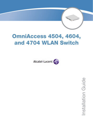
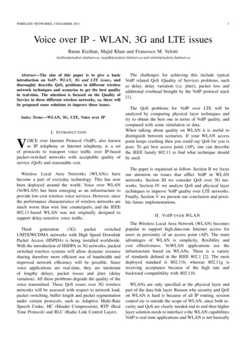
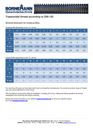
The Position of 802.11 as an IEEE StandardThe Standard 802.11, which the focus of this application note, coversprotocols and operation of wireless networks. It only deals with the 2 lowestlayers of the OSI reference model:Device ADevice B7 - Application Layer7 - Application Layer6 - Presentation Layer6 - Presentation Layer5 - Session Layer5 - Session Layer4 - Transport LayerPeerCommunications3 - Network Layer2 - MAC Layer4 - Transport Layer3 - Network Layer2 - MAC Layerdefined by 802.11PLCP1 - Physical LayerPLCP1 - Physical LayerNetworkFigure 1 – The Layers of the OSI reference model applying to 802.11As we can see from Figure 2, 802.11 describe the physical layer and theMedia Access Control (MAC) layer. A layer is inserted in between to definethe layer interface which is called Physical Layer Convergence Protocol(PLCP).The influence of other 802 Standard parts on 802.11 can be seen in thefigure below:Network Layer802.1 Management802.2 Logical Link ControlDataLinkLayer802.1 Y802.14PHY802.15PHY802.16PHYPhysicalLayerTransport Media (Air, Cable, .)Figure 2 – 802 Standards in the OSI contextFor 802.11, some physical layer implementations besides 802.11a/b/gexists which will not be covered in this application note. The figure belowgives a brief overview.1MA69 2e6Rohde & Schwarz
Frequency Allocation802.11Physical Layer802.11 IR(Infrared)1Mbps2Mbps802.11FHSS@ 2.4 GHz1Mbps2MbpsDSSS@ 2.4 GHz802.11 DSSS1Mbps2MbpsOFDM@ 5 GHz802.11 a802.11 ps18Mbps36Mbps54MbpsFigure 3 – Overview over standardized 802.11 physical layer systemsFrequency AllocationFrequencies for WLAN are allocated in 16 channels for 802.11a 14 channels for 802.11b/gChannels are assigned in different countries according to nationalregulations. Table 2 gives an overview over the national regulations.1MA69 2e7Rohde & Schwarz
eJapan(TELEC)Japan(MKK)FranceSpainEMEA(ETSI)5 1705 1805 1905 2005 2105 2205 2305 2405 2605 2805 3005 3205 5005 5205 5405 5605 5805 6005 6205 6405 6605 6805 7005 7455 7655 7855 8052 4122 4172 4222 4272 4322 4372 4422 4472 4522 4572 4622 4672 4722 4Assigned in / ationTable 3 – 802.11 regional regulations in channel allocationRelation between channel and frequency: 802.11a: Frequency 5000 MHz (Channel-Nr. * 5 MHz) 802.11b/g: Frequency 2407 MHz (Channel-Nr. * 5 MHz)ModulationOverviewThe following table gives an overview of the available 802.11a/b/gmodulation schemes including mapping and coder rates:1MA69 2e8Rohde & Schwarz
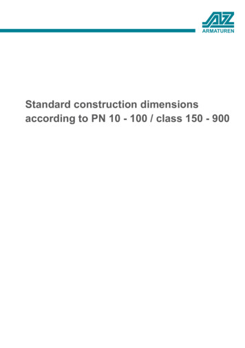
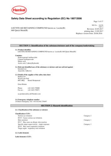
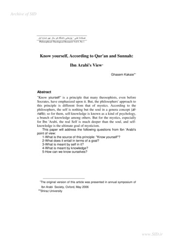
ModulationStandardData Rate ModulationDataPilotCoding[Mbit/s] per Charrier Charriers Charriers Ratefrom6BPSK4841/248 Bits9BPSK4843/448 Bits/296 Bits12QPSK4841802.1118QPSK4843/496 Bitsa/g2416QAM4841/2192 Bits43/4192 Bits41/2288 Bits/4288 Bits364816QAM64QAM48485464QAM48431DBPSK101/111 Bit2DQPSK102/112 Bits01/24 Bits1/21 Bit18 38PSK1)1/21 Bit012 Bit012 BitMappingto1 OFDMsymbol1 OFDMsymbol1 OFDMsymbol1 OFDMsymbol1 OFDMsymbol1 OFDMsymbol1 OFDMsymbol1 OFDMsymbolUsing48 BPSKcharriers48 BPSKcharriers48 QPSKcharriers48 QPSKcharriers48 16QAMcharriers48 16QAMcharriers48 64QAMcharriers48 64QAMcharriersBarker11 BitSequences11 ComplexBarkerIQ Values Sequences8 ComplexCCKIQ Values1/2 ComplexPBCCIQ Value8 ComplexCCKIQ Values1 ComplexPBCCIQ Value1 ComplexPBCCIQ Value1 ComplexPBCCIQ Value441)Clock switch from 11 Mchips/s to 16.5 Mchips/s after the preamble phaseTable 4 – Overview over the 802.11 modulation schemes and mappings802.11aThe Standard 802.11a uses an Orthogonal Frequency Division Multiplex(OFDM) transmission technique including 8 different data rates.To design an easy-to-implement transmission system, 64 carriers aredefined, but only the inner 52 carriers (-26 . -1, 1 . 26) are utilized. 4 pilotcarriers ( 21 and 7) are transmitting a fixed pattern, while the otherscarrier contain the data. The carrier spacing of 312.5 kHz leads to anominal signal bandwidth of 16.6 MHz.The data content of the carriers change every 4 µs (the slot time), exceptfor the preamble period, where the slot time is 8 µs. The preamble contains training sequence information used by thereceiver for frequency correction and channel estimation. The following signal field (4 µs length) contains information on themodulation, the length of the transmission, and other additionalinformation. The PLCP Service Data Unit (PSDU) which contains the informationfollows.The picture below shows a spectrogram representation of the 802.11asignal as described above.1MA69 2e9Rohde & Schwarz
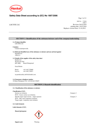
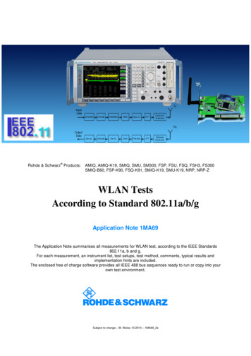
Modulation- 26- 24- 20- 16- 12-8-40 4 8 12 16 20 24 ime [µs]Figure 4 – 802.11a spectrogram representation (carriers vs time)Each of the 48 data carriers can be modulated with BPSK, QPSK, 16QAMor 64 QAM. This leads - in combination with different coding rates - to anominal data rate of 6 to 54 Mbit/s. The different constellations are shown inthe figure below. The index of b represents the distribution of the bit streamon the constellation points.(Green and red points are also occupied by blue ones, green points also byred ones)Qb1 1b2b3 00b 3b4b5 000 7b 3b 4b 5 001 5b2b3 01b3b4b 5 011 3b3b4b 5 010 1b3b4b5 110-7-5-3-1b2b3 11b3b4b5 111 3 5 7I-3b 3b 4b5 101-5b1 0b2b3 10b 3b 4b5 100BPSKQPSK16-QAM64-QAM 1-1-7b0 0b0 1b0b1 00b0b1b2 000b0b1b2 001b0b1 01b0b1b2 011b0b1b2 010b0b1b2 110b0b1 11b0b1b2 111b0b1b2 101b0 1b0 0b0b1 10b0b1b2 100Figure 5 – 802.11a carrier constellations802.11b802.11b uses an BPSK / QPKS transmission technique including 4 differentdata rates.1MA69 2e10Rohde & Schwarz
ModulationFor 1 and 2 Mbps – the 2 lowest modulation data rates – a Barkersequence in combination with DBPSK or DQPSK is defined.The Barker sequence used in 802.11b is defined as an 11 bit sequence(101101110000) which has good auto-correlation properties.The figures below show the modulation signal generation for 1 and 2 Mbit/soperation:Barker sequence1 bit1 MbpsDBPSKmapping1 BPSK symbol11 BPSK chips1 Msymbol/s11 Mchips/sBarker sequence2 bit2 MbpsDQPSKmapping1 QPSK symbol11 QPSK chips1 Msymbol/s11 Mchips/sFigure 6 – 802.11b 1/2 Mbit/s operationFor 5.5 and 11 Mbps, 2 different types of modulation are defined:CCK (Complementary Code Keying) uses a combination of bit-sequenceselection and DQPSK modulation:CCK mapping4 bit2 bit5.5 MbpsChoose 1 out of 48-chip sequencesDQPSKmapping8 QPSK chipsDQPSKmapping8 QPSK chips11 Mchips/s2 bit (d0,d1)CCK mapping8 bit11 Mbps6 bitChoose 1 out of 648-chip sequences11 Mchips/s2 bit (d0,d1)Figure 7 – 802.11b 5.5/11 Mbit/s operation1MA69 2e11Rohde & Schwarz
Packet format802.11g802.11g combines the 2 802.11a and b Standards, using both at thefrequency of the 2.4 GHz band ( 802.11b channels), and adding 2 optionaldata rates of 22 and 33 MBit/s with a 802.11b-like modulation.The following table shows the available 802.11g modes and their origin:NameData Rates [Mbit/s]Derived from1, 2802.11b5.5, 11802.11bERP-OFDM6, 9, 12, 18, 24, 36, 48, 54802.11aERP-PBCC5.5, 11, 22, 33802.11b6, 9, 12, 18, 24, 36, 48, 54802.11a bERP-DSSSERP-CCKDSSS-OFDMTable 5 – Overview over the 802.11 modulation schemes and mappingsPacket formatThe images below are a short overview of the packet format of 802.11a/b/g. For detailed information, please refer to the Standard [3] - [4].802.11aFragment4 bitSequence12 bitMAC headerFrameControl2 bytes8 µs8 µsShort trainingsequence10 symbols (repetition)Long trainingsequence2 symbols (repetition)12 carriers used53 cassiers usedDuration/ID2 bytesAddress 1 Address 2 Address 3 Sequence Address 4Control6 bytes6 bytes6 bytes2 bytes6 bytesFRAME BODYFCS0 . 4095 bytes4 bytesPLCP headerRATE4 bitsRes1 bitLENGTH12 bitsPar1 bitTail6 bitsSERVICE16 bitsCoded OFDM, BPSK, r 1/2 (6 MBit/s)PSDUTail6 bitPadBitsCoded OFDM, rate indicated by SIGNAL16 µs4 µsN x 4 µsPLCP preamble12 SymbolsSIGNAL field1 OFDM symbolDAT
The Application Note summarises all measurements for WLAN test, according to the IEEE Standards 802.11a, b and g. For each measurement, an instrument list, test setups, test method, comment