Transcription
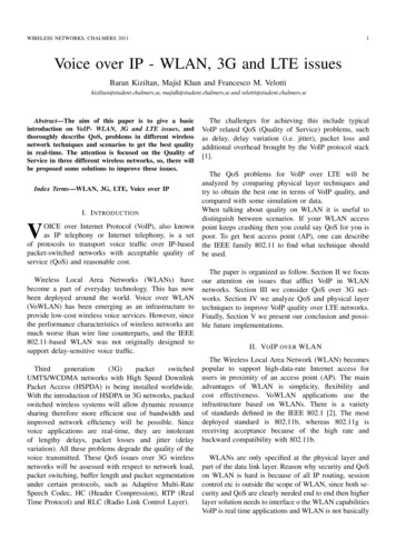
WIRELESS NETWORKS, CHALMERS 20111Voice over IP - WLAN, 3G and LTE issuesBaran Kiziltan, Majid Khan and Francesco M. Velottikiziltan@student.chalmers.se, majidk@student.chalmers.se and velotti@student.chalmers.seAbstract—The aim of this paper is to give a basicintroduction on VoIP- WLAN, 3G and LTE issues, andthoroughly describe QoS, problems in different wirelessnetwork techniques and scenarios to get the best qualityin real-time. The attention is focused on the Quality ofService in three different wireless networks, so, there willbe proposed some solutions to improve these issues.Index Terms—WLAN, 3G, LTE, Voice over IPI. I NTRODUCTIONVOICE over Internet Protocol (VoIP), also knownas IP telephony or Internet telephony, is a setof protocols to transport voice traffic over IP-basedpacket-switched networks with acceptable quality ofservice (QoS) and reasonable cost.Wireless Local Area Networks (WLANs) havebecome a part of everyday technology. This has nowbeen deployed around the world. Voice over WLAN(VoWLAN) has been emerging as an infrastructure toprovide low-cost wireless voice services. However, sincethe performance characteristics of wireless networks aremuch worse than wire line counterparts, and the IEEE802.11-based WLAN was not originally designed tosupport delay-sensitive voice A networks with High Speed DownlinkPacket Access (HSPDA) is being installed worldwide.With the introduction of HSDPA in 3G networks, packedswitched wireless systems will allow dynamic resourcesharing therefore more efficient use of bandwidth andimproved network efficiency will be possible. Sincevoice applications are real-time, they are intolerantof lengthy delays, packet losses and jitter (delayvariation). All these problems degrade the quality of thevoice transmitted. These QoS issues over 3G wirelessnetworks will be assessed with respect to network load,packet switching, buffer length and packet segmentationunder certain protocols, such as Adaptive Multi-RateSpeech Codec, HC (Header Compression), RTP (RealTime Protocol) and RLC (Radio Link Control Layer).The challenges for achieving this include typicalVoIP related QoS (Quality of Service) problems, suchas delay, delay variation (i.e. jitter), packet loss andadditional overhead brought by the VoIP protocol stack[1].The QoS problems for VoIP over LTE will beanalyzed by comparing physical layer techniques andtry to obtain the best one in terms of VoIP quality, andcompared with some simulation or data.When talking about quality on WLAN it is useful todistinguish between scenarios. If your WLAN accesspoint keeps crashing then you could say QoS for you ispoor. To get best access point (AP), one can describethe IEEE family 802.11 to find what technique shouldbe used.The paper is organized as follow. Section II we focusour attention on issues that afflict VoIP in WLANnetworks. Section III we consider QoS over 3G networks. Section IV we analyze QoS and physical layertechniques to improve VoIP quality over LTE networks.Finally, Section V we present our conclusion and possible future implementations.II. VO IP OVER WLANThe Wireless Local Area Network (WLAN) becomespopular to support high-data-rate Internet access forusers in proximity of an access point (AP). The mainadvantages of WLAN is simplicity, flexibility andcost effectiveness. VoWLAN applications use theinfrastructure based on WLANs. There is a varietyof standards defined in the IEEE 802.1 [2]. The mostdeployed standard is 802.11b, whereas 802.11g isreceiving acceptance because of the high rate andbackward compatibility with 802.11b.WLANs are only specified at the physical layer andpart of the data link layer. Reason why security and QoSon WLAN is hard is because of all IP routing, sessioncontrol etc is outside the scope of WLAN, since both security and QoS are clearly needed end to end then higherlayer solution needs to interface o the WLAN capabilitiesVoIP is real time applications and WLAN is not basically
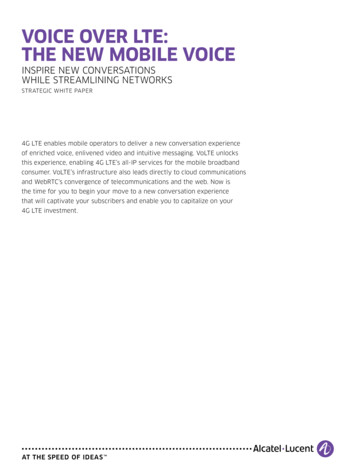
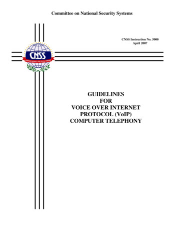
WIRELESS NETWORKS, CHALMERS 20112TABLE IQOSFig. 1.VoIP over WLAN [3]made for real time application because the QoS which isbig issue with WLAN is important and main portion ofVoIP applications. Challenges VoWLAN: there are manychallenge in VoWLAN like Quality of Services (QoS),security etc QoS in VoWLAN consist of these three thingwhich is discussed below.A. Packet LossThe total number of packet transmit over the networkis not receive to the end point or destination, so it meansthe some data or packet loos or not received by the destination. There are two main sources of packet losses:oneis network packet losses, mainly due to network congestion (router buffer overflow), link failures and rerouting,transmission errors, etc; and the other is discarded packetlosses for packets experienced excessive delay.B. DelayThe time taken by a packet to reach from a sourceto destination, delay can be occurred from differentsources like delay at source, delay at receiver, delayin network. Delay at source and receiver is due tocoding like changing analog to digital and digital toanalog and packetization, while network delay is dueto transmission, queuing and propagation.C. JitterThe variation of time between packet transmit fromsource to reach destination, means one packet reach in100 ms and one reach in 125 ms to handle this problemjet-buffer is used at receiving end and it has two typestatic jet-buffer which hardware base and dynamic basewhich is software base and can be handle by administrator .but should take care about jet-buffer because sometime it is also becoming reason for delay like memoryover-flows etc. The following are the some measurementand recommendation of ITU-T G.114 for a VoIP call forthe three attribute which is define in tab. I [5]. “Factorssuch as packet delay, jitter, packet loss and networklatency can noticeably affect the quality of UDP- basedPacket delayPacket lossJitter 150 ms 1% 25 msservices such as VoIP and video streaming. Contrary toTCP-based services such as HTTP, SMTP, etc, a steadystream of data packets is crucial for VoIP connections,where even slight connectivity problems can cause noiseor echo”. “Quality of any service depends on the trafficflow as well as the network of terminating partners.Following are some issues should be considered toprovide better-quality service. Number of calls managedsimultaneously by the network The alternate way totransfer the call to it desired destination in case of anyfault/failure occurred in the network CODECs for codingand encoding purposes. Overall setup of the network”[6].D. Original IEEE 802.11 MAC layerThe original IEEE802.11 has no idea QoS especiallyfor voice data application have no sensitivity about Delayjitter. The basic MAC layer use distributed coordination function (DCF) and Point coordination function(PCF ) to share medium with station both have severallimitation [2]. DCF relies on CSMA/CA and optional802.11 RTS/CTS to share the medium between station.The problem in DCF is that if many station want tocommunicate at the same time there is always a collisionoccur and it is based on collision avoidance means it hasto wait the medium to be free which produce delay andif collision occur it is waste of the bandwidth and makecommunication slow. some problem in DCF: there is no QoS guaranty and priority between datatraffic like voice and data; if a station sense medium and it is free andget medium to communicate no other can’tcommunicate until it didn’t let free the mediumif a station has slow bit rate it will capture themedium for along time.PCF is the other coordination which is define by basic IEEE802.11. It is optional. PCF is used only ininfrastructure mod in which all station are connectedby one center object called Access Point (AP). PCFdefine two frame Contention Free Period (CFP) andContention Period (CP). In the CP DCP is used. Togive the right of communicate over the medium the CFPsend Contention-Free-Poll (CF-Poll) to station at timeone packet each. The AP is coordinator. PCF has a little
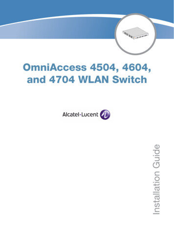
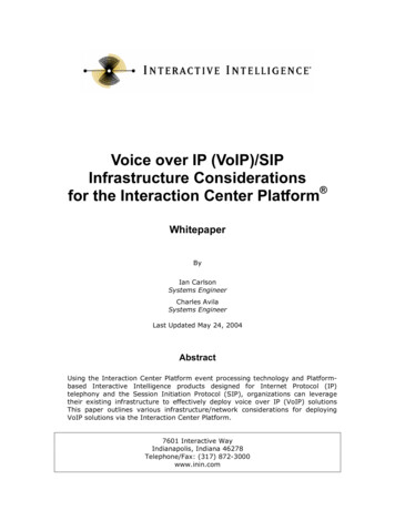
WIRELESS NETWORKS, CHALMERS 20113bit QoS management but have no idea of the differentclass of traffic.E. IEEE 802.11eThis standard define enhancement in the originalIEEE802.11 Mac layer DCF and ECF with new coordination function Hybrid Coordination Function (HCF). Itproposed priority and class based traffic means the voiceand multimedia application data class will have highpriority during transmission compare with other data likeemail data class in a shared wireless medium etc. Thereare two method to access the channel to communicatelike original IEEE802.11 MAC. HCF Controlled Channel Access (HCCA) and Enhanced Distributed ChannelAccess (EDCA)[6]. With the EDCA the data whichhave high priority will have have chance to send earlythen the low priority data and station having EDCAimplemented will have to wait less to send data. It workmostly like PCF. In PCF scenario the interval betweento beacon frame is divide into two period CFP and anCP, the HCCA is allowing the CFP to initiated almostany time during CP. This kind of CFP is called AccessPhase (CAP) in 802.11e. The AP will initiate CAP anytime which it want and can receive frame from othercontention-free manner. The CAC is a method whichwill decide whether a new connection will be allowto established or not, it will be decide on the basisof capacity of WLAN means if the new connection isallowed what will be MOS or quality of over all callwhich would be specified. So the CAC will maintain theover all quality of Voice of VoWLAN. For infrastructuremode of VoWLAN the CAC can be implemented in AP.Codec is used to convert voice signal to digitally encodedversion compress it on the sender end and then reversethe processes on the receiver end. These codec arestandardized by International Telecommunication (ITUT). There are many codec technique which is used inVoIP for Encoding and Decoding. Some coding and itdifferent result are mentioned in below table fig.2 whichhas been calculated with different IEEE 802.11 standardwith sample period 20, and voice activity detection active[8].The above data int the table is calculated by [9]Connect 802 VoIP Bandwidth Provisioning Calculator: from the table we got different result from differentcode which different bit rate per kbps and with havedifferent WLAN IEEE802.11 like a,b,g and got differentMOS and found how much simultaneously connection orcalls can be established at time on per AP. Among weobserve that Codec G.711 have high MOS rate and withreasonable simultaneously calls at time. But it shouldFig. 2.VoIP over WLANbe care about the bandwidth of connection is ok forrequirement of codec selected like G.711 require at least128 bit for both way communication. MOS is International Telecommunications Union TelecommunicationStandardization sector (ITU-T) approved which givesa numerical indication of the perceived quality of themedia received after being transmitted and eventuallycompressed using codec. The WLAN are working onradio wave which are open which can eavesdrops andsome one can manage to use it illegally like crack thesecret key.F. IEEE 802.11iThe IEEE802.11e enhance the security issue of original WLAN and put forward the WAP2, it using Advanced Encryption Standard (AES) block cipher. TheWEP and WAP were using RC4 stream cipher. TheIEEE802.11e replace the issue of Authentication andprivacy issue with more detail and security adjustment[9]. Different VLAN can be used to separate Voice trafficand data traffic: it will solve the space problem andvoice device can be protected from external network.Separate VLAN will have private addresses which willhide phone device from directly connected to publicnetwork; QoS trust boundary extension to voice devicesQoS trust boundaries can be extended to voice deviceswithout extending these trust boundaries and, in turn,QoS features to PCs and other data devices; protectionfrom malicious network attacks-Subnet access control,can provide protection for voice devices from maliciousinternal and external network attacks such as worms,denial of service (DoS) attacks, and attempts by datadevices to gain access to priority queues; ease of management and configuration-Separate VLANs for voiceand data devices at the access layer provide ease ofmanagement and simplified QoS configuration.III. VO IP OVER 3GTraditionally, real-time services (e.g. voice) aretransported over dedicated channels because of their
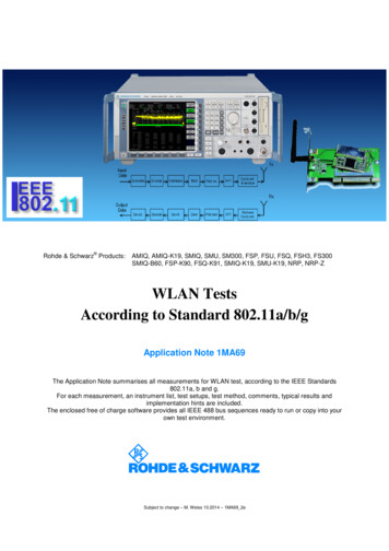
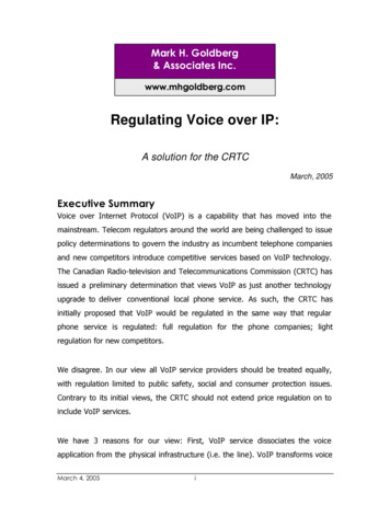
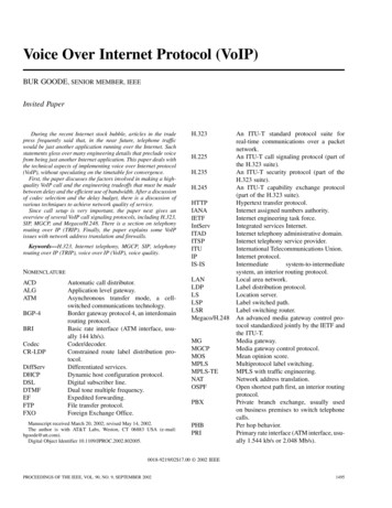
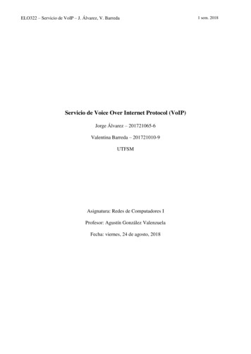
WIRELESS NETWORKS, CHALMERS 2011Fig. 3.Transport of speech in IPdelay sensitivity while data is transported over sharedchannels because of its transmitted in short, unevenspurts. In order to carry voice on IP networks,appropriate protocols must be used. The main protocolsare Real Time Protocol (RTP), User Datagram Protocol(UDP) and Internet Protocol (IP) [11]. In Fig. 1, thevoice frames are generated in the application layer,encoded and encapsulated within payload of an RTPSDU. The RTP PDU is encapsulated into an UDP SDU,which is delivered to the IP layer.Adaptive Multi-Rate Speech Codec (AMR) is a codecwith 8 narrow-band speech encoding modes with bitrates between 4.75 and 12.2 kbps. If the data rateis 12.2 kbps, the AMR codec generates packets of244 bits which represent voice frames of 20 ms [12].Since the AMR codec encodes and decodes digitalspeech data with an optimum power and bandwidthconsumption, the Internet Engineering Task Force(IETF) has approved the RTP payload format for AMR.Real Time Protocol (RTP) is an end to end transportprotocol, used to transport multimedia traffic in IPnetworks, supporting unicast and multicast traffic. In thecase of VoIP service, it is implemented together withUDP/IP [11]. Since RTP does not provide any reliabilitymechanisms and other layers should be implemented.AMR and RTP the main performance parameters forVoIP quality that are described earlier, can be measuredby the RTP protocol. RTPAMR and RTP The main performance parameters forVoIP quality that are described earlier, can be measuredby the RTP protocol.User Datagram Protocol (UDP) as a transport layerprotocol for VoIP over Internet Protocol (IP), UDP isused to avoid any retransmission delays. On the otherhand, it provides no reliability on datagram delivery.The UDP header size is standardized in 8 bytes and 204Fig. 4. FER for several loads and channel error for Simulation 1[11]bytes for IPv4 or 40 bytes for IPv6.Header Compression (HC) in 3G networks it isimportant to use bandwidth efficiently. On the otherhand, large headers of the protocols used when voicedata is sent over the wireless network where a high biterror rate (BER) due to fading and mobility is present.Robust Header Compression (ROHC) protocol has beendeveloped for this problem. The effective compressionmakes use of the fact that majority of the fields inthe combined IP, UDP and RTP header either remainconstant or introduce constant change throughout asession.A. QoS AnalysisOne main parameter for assessing packet loss is FER(Frame Error Rate). Although packet loss is undesiredsome loss can be tolerated since error-concealmenttechniques can be used. Buffer length can also causepacket loss due to discarding of delayed packets. Onthe other hand buffer length also may also increase thedelay where for acceptable conversational quality, themaximum end-to-end delay should be around 250-300ms [13]. Therefore buffer length takes an important roleshort buffering time will risk buffer underflows causingjitter, and long buffering time causes long delay andbuffer overflows. Too short buffering time may alsocause increased packet loss due to loss of segmentedpackets. Simulation with parameters specified for 2 different simulations can be seen in tab. II.From the first simulation it can be seen that fordifferent error probabilities, ranging from 1% to 10%,packet loss is directly related to the load on the wirelessnetwork. With the increase number of network users,applied packet switching technique is not feasible.Therefore it can be said that delay and delay jittermainly depends on both Round Robin switching
WIRELESS NETWORKS, CHALMERS 20115TABLE IIS IMULATION PARAMETERSParameterValue (Simulation 1)Simulation runs10000Value (Simulation 2)6min30sof speechLoadVariableOne userChannel bilityAMR sourcedata rateAMR voiceframe durationCall duration120s390sSilenceVoice on/offSilence Descriptor (SID)periods(mean duration 3s)(160 ms intervals)AMR voice244bits244bitsProtocol StackRT P U DP IP v4RT P U DP IP v6size 40 byte 60 byteHeaderRobust HCRobust und-RobinNonepacket payloadFig. 6. PDF of the mean packet delay jitter for several channel errorfor Simulation 1[11]sizeCompression (HC)RLC modeMaximum numberof MAC-hsretransmissionsNumber ofMAC-hs H- ARQFig. 7.parallel processesPacket schedulingSimulation Results for Simulation 2[1]algorithmDelay budget100msPredefined jitterbuffer (FIFO algorithm)packet loss ratio increases on the wireless channel, totalpacket loss rate increases. The reason for occurrence oferroneous packets in loss-free simulation is due to thepacket segmentation at RLC (Radio Link Control Layer),where packets larger than one TTI (Time Transfer Interval) are segmented over several TTIs, introducing longertransmission delays and packet drops.IV. VO IP OVER LTEFig. 5.Mean packet delay for several loads and channel forSimulation 1[11]technique and Hybrid-ARQ mechanism where themain features of MAC-hs (Medium Access Controlhigh speed) protocol of HSDPA are retransmissionof erroneous packets which is handled by H-ARQand sequential delivery of the packets to the upperlayer [14]. This reasoning can also be seen in the PDFof delay jitter for 5 fixed users on the network in figure 7.In simulation 2, a predetermined buffer is implemented; therefore average network delay is constantfor different error probabilities. On the other hand asThere are two important conditions must be met toensure an adequate VoIP quality:1) delay from sender to receiver must be as low aspossible;2) packet loss must be between 1% to 3%.So, in LTE, end-to-end Quality of Service is basedon two parameters that formalize these two conditions.First, Layer 2 Packet Delay Budget is specified forevery connection and for every User Equipment (UE).Second, Layer 2 Packet Loss Ratio is defined in orderto guarantee the above specification. Hence, if a VoIPconnection has a L2PDB of 100 ms and a L2PLRof 2% it mens that the QoS level for a subscriber issatisfactory. [16]In wireless networks, like LTE, the principal causeof issues is the path between the radio base-station and
WIRELESS NETWORKS, CHALMERS 20116the UE. In fact, there are many new physical layertechniques made to try to avoid the bit errors and thedelay, for example: Hybrid automatic repeat request(HARQ) or advanced channel coding. Given that LTE isstrongly dependent on HARQ, reducing the bit errors,the delay over the connection link will be reduced aswell. [16]LTE Hybrid ARQ is a physical layer technique toincrease robustness against transmission errors, and toincrease capacity. It is part of the MAC layer but thesoft-combining operation is handled by the physicallayer. In this technique, the erroneously received packetis stored in a buffer memory and later combinedwith the retransmission to obtain a single, combinedpacket which is more reliable than its constituents.Decoding of the error-correcting code operates an thecombined signal. If the decoding fails, a retransmissionis requested. [17]There are four kind of HARQ schemes, the first one iscalled Type I HARQ and it is based on the use of CyclicRedundancy Check (CRC), the second one is Type I CCHARQ because it is the same of the first one, but it uses aChase combining technique, the third one is Type II FullIR (Incremental Redundancy) and it gradually decreasescoding rate in each transmission by sending additionalredundancy bits [18] and the last one is Type
VoIP for Encoding and Decoding. Some coding and it different result are mentioned in below table fig.2 which has been calculated with different IEEE 802.11 standard with sample period 20, and voice activity detection active [8]. The above data int the table is calculated by [9] Connect 802 VoIP Bandwidth Provisioning Calculator