Transcription
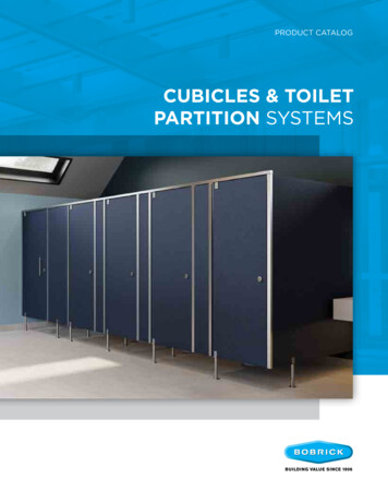
Panel Cubicles – K32Product Reference: Rearo Imperial CubiclesManufacturer:Address:T:E:Web:Rearo Laminates29 Loanbank Quadrant, Glasgow G51 3HZ0141 440 alPanels:Height (overall): Standard 1950mm FFL.Floor Clearance: 150mm.Depth: Standard 1500mmCore material: Moisture Resistant Chipboard with HPL.Thickness: 20mm.Colour: From the Rearo Cubicle and Washroom collection.Edge treatment: All edges square & lipped with 2mm PVC edging.Wall Support: Polished aluminium U – Channel brackets with Anti Vandal fixingsPilasters:Panel Height: 1800mm.Core material: Moisture Resistant MDF with HPL.Thickness: 32mm.Colour: From the Rearo Cubicle and Washroom collection.Edge treatment: Veritcal edges Postformed, Horizontal edges square & lipped with 2mm PVC edging.Ironmongery: Polished aluminium L – Brackets.Doors:Panel Height: 1800mm.Core material: Moisture Resistant Chipboard with HPL, Pre-drilled to suit Hinge and Indicator bolt positions.Thickness: 20mm.Colour: From the Rearo Cubicle and Washroom collection.Edge treatment: All edges square & lipped with 2mm PVC edging.Ironmongery: Indicator Bolt – Polished aluminium coin operated emergency release including keeper withconcealed fixings. Hinges - Polished aluminium butt hinges with nylon cams to set closed door position. CoatHook: Polished aluminium coat hook with buffer.Fittings:Headrail: Polished aluminium ‘D’ section.Legs: Polished aluminium 150mm high adjustable legs.Accessories:Headrail End Caps: Polished aluminium, to suit corner sited / free standing cubicles.Outward Opening Keeper: Polished aluminium, to suit outward opening doors.INSTALLATION Programming: Do not install cubicles or duct/ wall panels before building is weathertight, wet trades have finished theirwork, wall and floor finishes are complete, and the building is well dried out.Accuracy: Set out to ensure frames and/ or panels and doors are plumb, level and accurately aligned.Modifications: Do not cut, plane or sand prefinished components except where shown on drawings.Fixing: Secure components using methods and fasteners recommended by the cubicle/ panel manufacturer. Preventpulling away, bowing or other distortions to frames, panels and doors.Moisture and thermal movement: Make adequate allowance for future movement.
GENERAL INSTALLATION GUIDECUBICLES, VANITY UNITS AND IPS
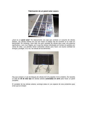
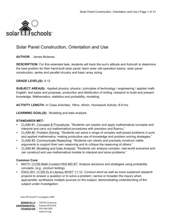
Washroom CubicleFitting InstructionsStep 1 MEASURING UPMeasure and mark off a vertical line on the back wall for thepositions of the partitions. Then mark on the wall thepositions to fix the 3 brackets.Existing WallStep 2 FITTING BRACKETSFix 3-No channel brackets as required for each partition onthe vertical line drawn on the wall. Brackets should be fitted100mm from top & bottom of partition and 1-No bracket inthe centre of the partition.InternalIndicator BoltStep 3 FITTING PARTITION SUPPORTAttach the support leg to the partition 100mm from the frontedge and adjust to the correct height. Ensure the partition isaligned correctly and fix the support to floor.ChannelBracketsStep 4 FITTING PARTITIONSEnsure the partition is level and fix brackets to the partitionusing the T-nuts provided.Step 5 FITTING FASCIA (PILASTERS)EndPilasterMark off the positions of the 3-No brackets on the fascia.Fix the channel brackets to the fascias 100mm from top &bottom of fascia with 1-No bracket in the middle of thefascia, then fix the fascia to the partition with T-nutsprovided. Imperial & Mercury Cubicles use 'L' brackets atthe end fascias.HeadrailDoorMidPilasterMid PartitionExternalIndicator BoltStep 6 FITTING HEADRAILWith the partitions and fascias permanently fixed, theheadrail must be cut to length, fitting end cap if required,then placed in position over the tops of the fascia's bridgingthe door gap.Fix the headrail permanently by attaching to the top of thefascias.EndPilasterDoor HingeStep 7 FITTING THE DOOR, HINGES AND LOCKASSEMBLY.Attach the hinges to the fascias and door, all as perspecified cubicle system, ensuring the door is hunghorizontal and level. Then attach the indicator bolt to thedoor as per specified fitting instructions. Engage the lockand mark off on the fascia the point to attach the keep.Unlock the indicator bolt and attached the keep using thefixings provided.Each of Rearo Laminates toilet cubicle system has specific /bespoke fitting instructions (supplied separately)For further instructions or technical assistance please contact Rearo on 0141 440 0800Support LegMounted on partitionEnd Partition
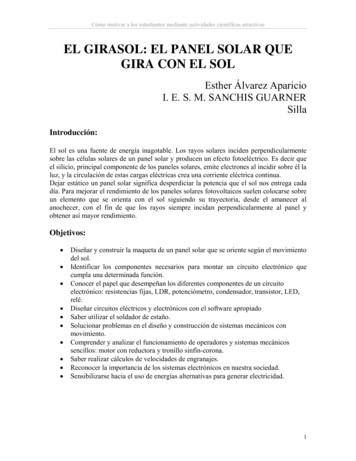
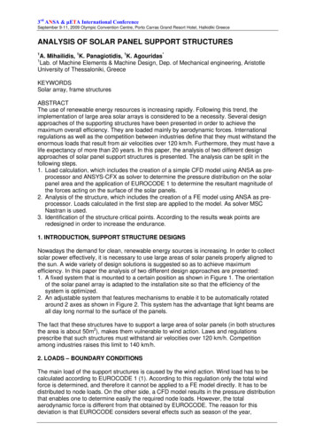
VANITY UNIT INSTALLATIONRapidFit vanity units are designed to be asversatile as possible, to allow standardcomponents to be used in all types of roomarrangements.It is assumed that all timber framing is provided bythe installer and constructed to suit the on sitedimensions. Treated timber should be used for thefirst fix and any cut outs made to the suppliedpanels, that would be exposed to moisture, mustbe suitably sealed. Sanitaryware and plumingitems are not supplied with these units.FITTING BETWEEN WALLSFor fitting Decor End Gable Panel or Semi Recessed Sinks - see page 2Shadow Gap material is supplied as three 150 x2800 x 18mm lengths. This material should be cuton site to the required site dimensions andscrewed on all inner edges to the timber framing,to ensure all fixings are hidden behind AccessPanels (as per diagram B).C40mmDecor End Panelrequires -40mmConstruct timber framing to suit the requiredVanity Unit dimensions A. Please ensure framingis built to a sufficient height to allow for skirting(normally 100mm) and Access Panels plus anadditional 20mm above the Access Panel to allowclearance for the Gravity Fixing Clips. A suggestedoverall framing height of 780mm is recommended.If Vanity Unit is corner sited, the framing needs tobe left 40mm short of Vanity Top - see Optional*Decor End Panel instruction (page 2).Framing for the Shadow Gap should be set back60mm from the depth of the Vanity Top to ensurethat, when the Access Panels are installed, anyexcess water dripping off the downstand will droponto the floor and not onto the Access Panel F.BAPosition screws insidearea to be covered byaccess panel. Paneladhesive can also beused in addition toscrew fixings.780mmLift-on Lift-offGravity Clips350mm500mm780mm150mm540mm100mmFRAMEDAccess Panel(s) are fixed by means of Lift-on Liftoff plastic Gravity Clips, the location of these clipson the panels and Shadow Gap will ultimately bedetermined by overall site dimensions. However,the Access Panel is manufactured 100mm shorterin length than the Vanity Top, to leave a suggestedvertical Shadow Gap of 50mm (as per diagram C).SHADOW GAPACCESS PANELE600mmF580mm40mmVanity Top overhangs40mm from frameat frontFix screws fromunder side of frameFix the Vanity Top to the framing by screwingthrough the framing on to the underneath of thetop. Please remember the top is 20mm thick, becareful to avoid screws breaking through the topsurface. (as per diagram E).Vanity Top align withside edge of framewhen fitting between wallsor overlap by 40mmif using Decor End PanelVanity Top mustover-hang AccessHatchShadow GapAccess Hatch540mm20mm20mmLIFT-ON LIFT-OFF GRAVITY CLIPSVANITY TOPIllustrations not to scaleREV 1 - 2017
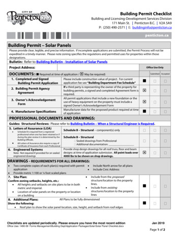
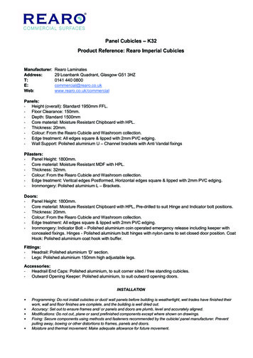
FITTING CORNER SITED UNITS Complete the End FrameOPTIONAL* DECOR END PANELAn additional pack is available for corner-sitedarrangements. In such a circumstance, theframing should be left 40mm short of the overallvanity length, and the Shadow Gap side edgeshould project 18mm past the frame. This is toallow the Decor End Gable Panel to master (tuckin behind) the Shadow Gap.G Top frame less 40mm to allow vanity topoverhangLarger Gable Panel is supplied at 560mm deep toallow scribe to wall. The panel should then befixed by screwing from the inside, if accessible,alternatively glue on the panel. If screws need tobe used from the outside, position above 600mmto avoid the screw heads showing (as per diagramG).Screw onlyabove 600mm650mmPanels are all manufactured from I8mm MoistureResistant Melamine Faced Chipboard (MR-MFC)and all visible edges are edged with a 2.0mmcolour matched PVC. The Vanity Top ismanufactured from Moisture Resistant MDF facedwith High Pressure Laminate. It is essential thatwhen site dimensions require panels to be cutdown on site that any edges, which may beexposed to moisture, are sealed with a suitablesealant. Similarly, all basin and plumbing holes andcut outs should be sealed to avoid prolongedcontact of the core to moisture. Alternatively the Shadow Gap can be fittedprojecting 18mm past the end frame to allowthe Décor End Gable Panel to master behindthe Shadow Gap. The exposed core of theShadow Gap can then be covered by gluing onthe additional PVC edging strip supplied withthe Décor End Kit.600mmThe small 580 x 180 x I8mm MDF return panel isthen glued to the underside of the Vanity Top (asper diagram H).The loose laminate is then glued (contactadhesive) to the exposed blocked end and shouldbe trimmed around the top and downstand toleave an attractive neat finish (as per diagram H). Panel supplied 560mm wide to allow for scribeto wall, should be fixed flush to front coveringShadow Gap edge.Vanity Top overhangsframe by 40mm whenfitting Decor End PanelShadow Gap extendspast frame by 20mm560mm20mmscribeDECOR END GABLE PANELHIRemove front edge of frameAdd middle strutto framePosition Upstandover Vanity TopGlue top and sideof trim to undersideof vanity topGlue laminate to trimAfter glueing, trim laminateto curved of vanity topCare and Maintenance:All panels should be cleaned with a damp clothand non-abrasive mild detergents.Please note: panels are manufactured for use in commercialwashrooms. However, they are not designed for prolongedcontact with water. Panels should not be submerged in orbe exposed to long term contact with water. Rapidfit panelsshould not be used in shower, sauna or steam rooms.DECOR END VANITY PANEL,LAMINATE & UPSTANDPOSSIBLE FRAMING WHEN USINGSEMI-RECESSED SINKS
IPS INSTALLATION GUIDEPrior to beginning your project, please check all materials are as per order and check drawings to suit required layout. Ifthere are any discrepancies, please contact Rearo’s Commercial Department to discuss (0141-440-0800).PREPARATIONSTEP 2: APPLICATION OFSTEP 3: INSTALLATION OFSHADOW GAPIPSAssess area for installation of IPS, noting any gradient on thefloor or walls, allowing this to be considered during installationTools required:3Using a spirit level, align and mark the required position of thetimber frame.- Screw Gun/ drill- Hand saw- IPS panels- Shadow Gap lengths- Lift on/ off clips (pack of 4 per panel)- Push on/ off clips (if required)- S/wood Timber- Spirit Level/ Laser Measure- Tape Measure- Suction Handle- PPE (if required)2STEP 1: FRAMING1Fig 3.14Keku clip detailFig 3Fig 2Fig 1 Install two outer shadow gaps [1&2] first, ensuring theyare plumb and level. If IPS has a return end rememberto extend face shadow gap by 20mm past theframework. This will ensure no visible join to the face ofthe panel. Refer to figure 2.1 Install sections 3 and 4 ensuring they are square andlevel Please note, when installing all s/gap strips, fix thestrips to the inside edge of the area. This way the fixingswill be hidden once the IPS panels are fitted. Install further mid s/gaps if required We recommend additional timbers where cubiclepartitions meet the framing. Refer to figure 2.2Fit part A of ke ku clips to inner edges of shadow gaps,align the bottom IPS panels in correct position ensuringit is level and mark the reverse to allow part b of the keku clips to be fitted. Screw and fit clips. Clip on the paneland ensure that it is level, adjust if necessary. See figure3.1Repeat above two processes until all IPS panels areinstalledWhen installing compact grade IPS panels, please notethe different type of screw fixings within the ke ku clipbags. This is to ensure the screw doesn’t burst the faceSTEP 4: COMPLETIONCut and install perimeter timber frame to the requiredlayout. Additional vertical timbers may be requiredwhere multiple runs of IPS are situated side by side.Please refer to Rearo’s project specific IPS layoutswhere applicable.Remove protective film from panels and shadow gapand to finish clean as per standard instruction (O&M)Fig 2.1Fig 2.1Fig 2.2
FURTHER INFORMATIONFor more information regarding Buhne or to book an appointment with Business Development Manager,Robert Bennett, please contact: E: robert.bennett@rearo.co.uk or alternatively M: 07919015647Rearo, Loanbank House, Loanbank Quadrant, Govan, Glasgow, G51 3HZTel: 0141 440 0800 Fax: 0141 445 3342 www.rearo.co.uk sales@rearo.co.uk
High Pressure Laminates (HPL)COSHH DATA SHEETManufacturer:Address:T:E:Web:Rearo Laminates29 Loanbank Quadrant, Glasgow G51 3HZ0141 440 al1. Product DescriptionHigh Pressure Laminate (HPL) Toilet Cubicles / IPS / Vanity Units by Rearo Laminates are a decorative Commercial Washroomsolution which can be used within all types of environments except from – locations where panels are in direct contact with waterand exposed to high levels of moisture (i.e Swimming Pools).2. Material SpecificationAll panels are manufactured using 0.7mm – 1.2mm High Pressure Laminate bonded to an 18mm MR Chipboard / 18mm MDFsubstrate with all exposed edges to be lipped in 2mm PVC edging.3. Area of UseFor interior use in dry commercial surface areas. Not suitable for use in wet areas.4. Hazards IdentificationHarmful by inhalation (dust / formaldehyde). Effects of skin contact are not fully known and may vary.5. Information on IngredientsSurface papers 9.9%; Melamine Formaldehyde Resin (CAS No. 9003-08-1) 9.9%; Kraft Papers 57.7%; Phenol FormaldehydeResin (CAS No. 9003-35-4) 22.5%.6. First Aid MeasureAfter inhalation:Remove from exposure. If discomfort persists, seek medical attention.After Skin Contact:Wash off with soap and water.After Eye Contact:Irrigate with water. If discomfort persists, obtain medical attention.After Swallowing:Wash out mouth with water.7. Accidental Release MeasuresSweep or vacuum wood dust for recovery or disposal, avoid generation of dusty conditions. Provide good ventilation.8. Handling and StorageWear heavy duty cut resistant gloves when handling laminate. Protect eyes with safety glasses. Ensure good ventilation andextraction systems to control dust levels when machining laminate. Care should be taken in high winds as laminates have sharprazor edges which can cause injury when propelled by the wind. Store laminates in a dry place away from sources of excessiveheat and on flat surfaces such as wooden pallets and cover the top laminate to protect from accidental damage. Stacked laminatesare liable to slip and split if hit with any force.9. Physical and Chemical PropertiesPanels manufactured in large sizes up to 3660 x 1525mm and may have one or two decorative surfaces. Density: 560 – 720KG/m3Release Date: 10/09/19R/HPL/SDS/19 Version 1Quality Management – Rearo LaminatesPage. 1
High Pressure Laminates (HPL)10. Exposure Controls / Personal ProtectionIn the workplace where laminates are machined and cut, adequate exhaust ventilation should be provided to remove dust andfumes. Workplace exposure limits of inhalable dust are required to be below 10mg/Nm3 in accordance with COSHH Regulations2002. Ensure good housekeeping is practiced to prevent accumulations of fugitive emissions and spills of dust which cancontribute to the risk of explosions.Respirator:Approved respirator under dusty conditions recommended.Ventilation:Local Exhaust: Due to explosive potential of wood dust when suspended in air, precautions shouldbe taken to prevent sparks or other ignition sources in ventilation equipment. Use of totallyenclosed motors is recommended.Gloves:Recommended to reduce skin contact, except where moving machinery parts expose fingers tohazards.Eyes:Safety glasses or goggles recommended.11. Stability and ReactivityThermal decomposition produces irrigating and toxic gasses including CO, aldehydes and organic acids. Avoid oxidising agentsand drying oils. Keep away from sources of ignition.12. Toxicological InformationQuantitative data on the toxicity of this product are not available. Chronic effects of skin contact with wood dust are not fully knownand may vary.13. Ecological InformationQuantitative data on the ecological impact of this product are not available. Adverse effects on the environment cannot beexcluded but unlikely when handled, stored, and disposed of appropriately.14. Disposal ConsiderationsThe supplier can recycle the product. Recycling is the preferred route. If recycling is not possible, the material should be sent forenergy recovery. Landfill is not advised but can be used as a last resort. It is however, the user’s responsibility to ensure wasteis disposed of in accordance with all the valid laws.15. Transport InformationHigh Pressure Laminate panels are not subject to transport legislation. Laminates should be securely strapped together to avoidslipping during transit. Edge protectors should be used to protect the laminate edges from strapping damage.16. Regulatory InformationWithin the UK, the use of this material must be assessed under the Control of Substances Hazardous to Health (COSHH)regulations.17. Additional InformationRearo Laminates manufacture under conditions controlled by management systems accredited to ISO 9001:2015, BS OHSAS18001:2007 and BS ISO 14001:2015 For further information, please view the Wood Panel Industry Federation (WPIF)website: www.wpif.org.uk for section 6 of the Panel Guide on Health & Safety.Provisional Note:This Safety Data Sheet has been carefully drawn up to the best of our knowledge. We accept no liability for any mistakes, errors instandards or printing errors. In addition, technical modifications can result from the continuous further development, as well as fromchanges in standards and documents originating from statutory bodies. The content of this document should therefore not be consideredas instruction for use or as legally binding.Release Date: 10/09/19R/HPL/SDS/19 Version 1Quality Management – Rearo LaminatesPage. 2
provided. Imperial & Mercury Cubicles use 'L' brackets at the end fascias. Step 6 FITTING HEADRAIL With the partitions and fascias permanently fixed, the headrail must be cut to length, fitting end cap if required, then placed in position over the tops of the fascia's bridging the door gap.