Transcription
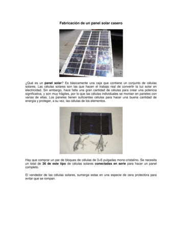
3rd ANSA & μETA International ConferenceSeptember 9-11, 2009 Olympic Convention Centre, Porto Carras Grand Resort Hotel, Halkidiki GreeceANALYSIS OF SOLAR PANEL SUPPORT STRUCTURES1A. Mihailidis, 1K. Panagiotidis, 1K. Agouridas*Lab. of Machine Elements & Machine Design, Dep. of Mechanical engineering, AristotleUniversity of Thessaloniki, Greece1KEYWORDSSolar array, frame structuresABSTRACTThe use of renewable energy resources is increasing rapidly. Following this trend, theimplementation of large area solar arrays is considered to be a necessity. Several designapproaches of the supporting structures have been presented in order to achieve themaximum overall efficiency. They are loaded mainly by aerodynamic forces. Internationalregulations as well as the competition between industries define that they must withstand theenormous loads that result from air velocities over 120 km/h. Furthermore, they must have alife expectancy of more than 20 years. In this paper, the analysis of two different designapproaches of solar panel support structures is presented. The analysis can be split in thefollowing steps.1. Load calculation, which includes the creation of a simple CFD model using ANSA as preprocessor and ANSYS-CFX as solver to determine the pressure distribution on the solarpanel area and the application of EUROCODE 1 to determine the resultant magnitude ofthe forces acting on the surface of the solar panels.2. Analysis of the structure, which includes the creation of a FE model using ANSA as preprocessor. Loads calculated in the first step are applied to the model. As solver MSCNastran is used.3. Identification of the structure critical points. According to the results weak points areredesigned in order to increase the endurance.1. INTRODUCTION, SUPPORT STRUCTURE DESIGNSNowadays the demand for clean, renewable energy sources is increasing. In order to collectsolar power effectively, it is necessary to use large areas of solar panels properly aligned tothe sun. A wide variety of design solutions is suggested so as to achieve maximumefficiency. In this paper the analysis of two different design approaches are presented:1. A fixed system that is mounted to a certain position as shown in Figure 1. The orientationof the solar panel array is adapted to the installation site so that the efficiency of thesystem is optimized.2. An adjustable system that features mechanisms to enable it to be automatically rotatedaround 2 axes as shown in Figure 2. This system has the advantage that light beams areall day long normal to the surface of the panels.The fact that these structures have to support a large area of solar panels (in both structuresthe area is about 50m2), makes them vulnerable to wind action. Laws and regulationsprescribe that such structures must withstand air velocities over 120 km/h. Competitionamong industries raises this limit to 140 km/h.2. LOADS – BOUNDARY CONDITIONSThe main load of the support structures is caused by the wind action. Wind load has to becalculated according to EUROCODE 1 (1). According to this regulation only the total windforce is determined, and therefore it cannot be applied to a FE model directly. It has to bedistributed to node loads. On the other side, a CFD model results in the pressure distributionthat enables one to determine easily the required node loads. However, the totalaerodynamic force is different from that obtained by EUROCODE. The reason for thisdeviation is that EUROCODE considers several effects such as season of the year,
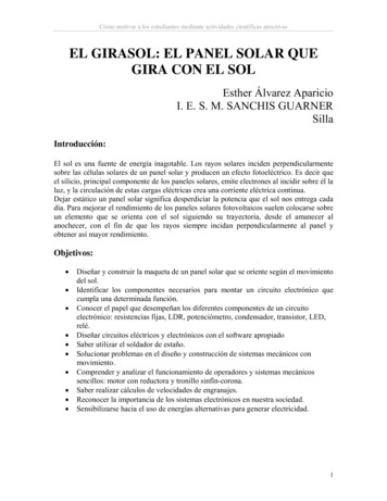
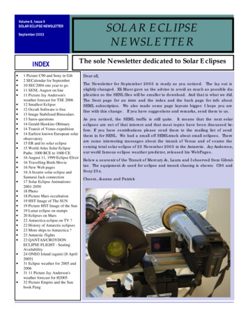
3rd ANSA & μETA International ConferenceSeptember 9-11, 2009 Olympic Convention Centre, Porto Carras Grand Resort Hotel, Halkidiki Greeceinstallation site, required service life, and so on, whereas most CFD models do not.Consequently both EUROCODE and CFD model must be used.Figure 1 – Design A: Fixed support structure design (EXEL MAKMETAL)Figure 2 – Design B: Adjustable support structure design (IRIS - PTOLEMEO)
3rd ANSA & μETA International ConferenceSeptember 9-11, 2009 Olympic Convention Centre, Porto Carras Grand Resort Hotel, Halkidiki GreeceLoad calculationWind direction is stochastic and therefore it is necessary to compute the pressure distributionfor a variety of wind directions, because it is usually very difficult to estimate which one is themost critical. In the current analysis the following wind directions are considered 0, 15, 165and 180 degrees. Figure 3 shows the CFD model and the boundary conditions for winddirection angle 0 degrees.Figure 3 – Fluid model, boundary conditions:1 Purple: Ground and plate2 Green: Opening where the relative pressure is 03 Blue: Given velocity with vector normal to the control volume surfaceThe aerodynamic loads are caused mainly by the solar panel array whose thickness is verysmall regarding its other dimensions. Therefore, it can be modelled as a thin plate consistingof shell elements in a control volume. The dimensions of the control volume are chosen largecompared to the dimensions of the plate. The model was solved using the ANSYS-CFX.Typical results are shown in Figures 4 and 5.Figure 4 – CFX Results: Air Streamlines
3rd ANSA & μETA International ConferenceSeptember 9-11, 2009 Olympic Convention Centre, Porto Carras Grand Resort Hotel, Halkidiki GreeceFigure 5 – CFX Results: Pressure distribution on the front and the back of the plateFrom these results the pressure distribution is obtained. Following, the resultant force andthe node loads can be determined.The resultant force results from the summation of the loads acting on each node.FCFX (FCFXbi FCFXfi )ni 1where:FCFXFCFXbiFCFXfinResultant force obtained from CFD modelForce on node i of the back side of the plateForce on node i of the front side of the plateNumber of nodesAs mentioned earlier the total force according to EUROCODE FEu differs from that obtainedby the CFD model. A scaling factor C can then be calculated.C FEuFCFXThe actually applied forces on the nodes are:Fnode C (FCFXbi FCFXfi )The procedure to import forces to the static model is the following:1. Export forces from ANSYS-CFX2. Export the geometry of the plate including the mesh from ANSA (2). The mesh must beretained so that the position and the number of the nodes remain the same3. Process of the forces by adding the force at the back and at the front node of the platescaled as mentioned above.4. Compose the NASTRAN load file5. Import the NASTRAN load file into the static FE model.3. STRUCTURE MODELLINGSince both structures designs consist only of thin-walled parts the 3-d solid parts importedfrom the CAD file must be first translated to surfaces as shown in Figure 6.Triangular and rectangular shell elements (CTRIAS and CTETRAS) (3) are used to modelthe resulting surface.
3rd ANSA & μETA International ConferenceSeptember 9-11, 2009 Olympic Convention Centre, Porto Carras Grand Resort Hotel, Halkidiki GreeceFigure 6 –Solid parts translated to surfacesFigure 7 – Shell meshFigure 8 shows the modelling bolted connections. RB2 elements are used to constrain theholes with the centre node and a CBAR element to model the body of the bolt. Since boltedconnections cannot support rotational loads, the torsional moment of inertia of the CBAR isset to zero.Figure 8 – Typical bolted connectionThe space frame of Design B consists of nodes and tubes. The nodes are modeled as shellelements and tubes as CBAR elements shown in Figure 9.
3rd ANSA & μETA International ConferenceSeptember 9-11, 2009 Olympic Convention Centre, Porto Carras Grand Resort Hotel, Halkidiki GreeceFigure 9 – Space frameCritical welds are modeled according to the Hot Spot Stress analysis (4) as shown in Figure10. This analysis requires that the stresses at certain positions are known, in order toextrapolate the results and obtain the Hot Spot stress at the welding.Figure 10 – Mesh used for Hot Spot Stress analysisIn modelling design A self-weight can be neglected, since it is supported by many rodsinserted in the ground. However the elastic properties of the ground have to be taken intoaccount. Depending on the installation site they must be determined by geotechnicalanalysis.Typical elastic properties are given in Figure 11.Vertical stiffnessHorizontal stiffnessTorsional stiffnessFigure 11 - Constrains of the base of design A7000 kN/m875 kN/m120 kNm/rad
3rd ANSA & μETA International ConferenceSeptember 9-11, 2009 Olympic Convention Centre, Porto Carras Grand Resort Hotel, Halkidiki GreeceIn design B the solar panels are attached to a space frame. It is connected by two hinges toan auxiliary frame. In this way it can be rotated around the horizontal axis. The completesupport structure rest on three rollers in a circular guide. In this way it can be rotated aroundthe vertical axis. Calculations were carried out for several angles for both horizontal andvertical axes. Moreover, the weight cannot be neglected in this design.Constrained rotational degree offreedom (Driving motor is attachedhere)Constrained transnational degrees of freedomFigure 12 – Constrains design B
3rd ANSA & μETA International ConferenceSeptember 9-11, 2009 Olympic Convention Centre, Porto Carras Grand Resort Hotel, Halkidiki GreeceFigure 13 – Final models ready to be solved4. RESULTSBoth models were solved using MSC Nastran. The solution types chosen initially were 101 –Linear Static and 106 – Non Linear Static taking into account large deformations andassuming linear elastic material behaviour. The comparison showed that the non-Linearsolution resulted in only insignificantly better accuracy but required considerably morecomputing time. Therefore, the Linear Static solution was chosen.The assumption of a linear elastic material behaviour is justified by the fact that the allowablemaximum Von-Mises stress is set far below the yield stress, because the structure mustwithstand the highly dynamic loads that actually occur.The following Figures 14 – 18 show some problems of the initial designs and how they wereresolved.Figure 14 shows the initial design of the support of a longitudinal frame member. Since it isfixed, the resulting stress field includes impermissible high values. In the improved designshown on the right of the Figure 14, the maximum stress is significantly reduced, by fixing thelongitudinal member to a U – formed attachment by a single pin.Figure 14 – Frame member supportThe maximum stress in the transverse frame member was significantly reduced by a finertriangulation near the end points as shown in Figure 15.Figure 15 – Triangulation of the transverse frame member
3rd ANSA & μETA International ConferenceSeptember 9-11, 2009 Olympic Convention Centre, Porto Carras Grand Resort Hotel, Halkidiki GreeceFigure 16 shows the reinforcements that were necessary to increase the load caring capacityof the auxiliary frame design.Figure 16 – Reinforcements of the auxiliary frameFigure 17 shows that the maximum stress be could significantly reduced by adding properlydesigned reinforcements.Figure 17 – Reinforcements of weldingsThe space frame of the design B consists, as mentioned above, from nodes and tubes.Tubes can only be loaded by tensile or compressive forces. In the later case Von-Misesstress as yield criterion is not enough for this part of the structure and buckling calculation isalso necessary.Figure 18 shows the forces used for buckling calculation of the tubes.
3rd ANSA & μETA International ConferenceSeptember 9-11, 2009 Olympic Convention Centre, Porto Carras Grand Resort Hotel, Halkidiki GreeceFigure 18 – 1d Element forces used for buckling calculationThe following figures 19 and 20 show the deformation and the stress field of the final designsof both structures.Figure 19 – Deformation and stress field of design AFigure 20 – Deformation and stress field of design B5. CONCLUSIONSEven fixed solar array support structures have sofisticated design, that needs to be analyzedand often improved in order to withstand the wind load. The same applies of course toadjustable designs to an even greater extend. The analysis has to be carried out for manywind directions. Therefore, it is very important to employ productive software tools. Thedesigns presented in this paper were analyzed using ANSYS – CFX, ANSA, MSC NASTRANand META (5) in a very efficient way. Further, it was possible to omit the time-consumingnon-linear solutions, because comparative calculations showed that the accurancy gainobtained by them is insignificand.Figures 21 and 22 show the installed solar arrays.
3rd ANSA & μETA International ConferenceSeptember 9-11, 2009 Olympic Convention Centre, Porto Carras Grand Resort Hotel, Halkidiki GreeceFigure 21 – Design AFigure 22 – Design BREFERENCES(1)Eurocode 1: Actions on structures - General actions - Part 1-4:Wind actions(2)ANSA version 12.1.5 User’s Guide, BETA CAE Systems S.A., July 2008(3)MSC.Nastran 2005 r3,Quick Reference Guide(4)International Institute of Welding, Recommendations for fatigue design of weldedjoints and components, June 2005(5)μETA Postprocessor, version 6.2.0. User’s Guide, BETA CAE Systems S.A., June2008
of the solar panel array is adapted to the installation site so that the efficiency of the system is optimized. 2. An adjustable system that features mechanisms to enable it to be automatically rotated around 2 axes as shown in Figure 2. This system has the advantage that light beams are all day long normal to the surface of the panels. The fact that these structures have to support a large .