Transcription
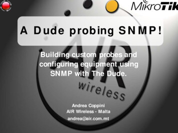
Dude, Where’s My Card? RFID Positioning That Works withMultipath and Non-Line of SightJue Wang and Dina KatabiMassachusetts Institute of Technology{jue w,dk}@mit.eduABSTRACTthe object is within radio range, which can be tens of meters [6].Many applications however would benefit from knowing the exactlocation of an RFID-tagged object. For example, in pharmacies, onewould want to periodically check that sensitive medications are oncertain shelves in a particular storage cabinet. Similarly, if you loseyour credit card, instead of simply learning it is in the room as youprobably already have guessed, you would like to know its exactlocation, e.g., whether it is under the couch, in the drawer, in thepocket of your coat, etc. Exact positioning information is also indispensable for some emerging RFID applications like automatedcustomer checkout: pilot programs of RFID-automated checkoutrevealed that “a shopper could end up paying for the groceries of theperson behind her”, because today’s systems confuse which basketthe RFID-tagged goods belong to [4].Fine-grained RFID localization has recently received much attention [32, 30, 20, 21, 29]. The two key approaches in this domainare based on received signal strength, i.e., RSSI, and the angle ofarrival, i.e., AoA. Some researchers augment these methods by considering multiple frequencies, or multiple receiving antennas [32,8, 41]. However, underlying both methods is an assumption thatthe signal is mainly propagating along a direct line-of-sight (LOS)path, which is unlikely in most practical RFID setups [42, 18]. Signals bounce off various reflectors in the environment, and multiplereflected copies combine at a wireless receiver, which underminespositioning metrics such as RSSI and AoA [43, 32]. This multipathphenomenon is inevitable in practice and is exacerbated in non-lineof-sight (NLOS) scenarios. Indeed, multipath is the natural mode ofoperation for UHF RFIDs, which were originally introduced to replace barcodes in non-line-of-sight settings [42].This paper introduces PinIt, the first fine-grained RFID positioning system that works in the absence of a line-of-sight path and thepresence of rich multipath. In line with common practice in locatingRFIDs [30, 28, 36], PinIt employs reference tags, whose positionsare known a priori. To locate a misplaced object, both the desiredtag attached to it and a set of reference tags are queried, and thenearest reference tags are identified. The challenge however is toidentify the nearest tags in a manner robust to multipath and NLOS.Unlike past approaches [32, 36, 29], which consider multipathas detrimental, PinIt exploits a tag’s multipath profile to locate it.Specifically, signals of nearby tags propagate along closer pathswhen being reflected off each surface. Hence, if we can obtain adescription of all the paths along which a tag’s signal propagates-i.e., its multipath profile - neighboring tags can be identified.To illustrate PinIt’s approach, Fig. 1 shows a toy example withthree tags, where the blue and green tags are separated by 10 cm,whereas the blue and red tags are separated by 60 cm. As the figureshows, signals from a pair of spatially separated tags, like the blueand red tags, may arrive along exactly the same path from one perspective, but tend to have significantly different paths from a secondperspective. In contrast, signals from nearby tags, like the blue andgreen tags, will always arrive along close paths. Hence, one needsto consider the full multipath profile; one path alone, like the pathRFIDs are emerging as a vital component of the Internet ofThings. In 2012, billions of RFIDs have been deployed to locateequipment, track drugs, tag retail goods, etc. Current RFID systems, however, can only identify whether a tagged object is withinradio range (which could be up to tens of meters), but cannot pinpoint its exact location. Past proposals for addressing this limitation rely on a line-of-sight model and hence perform poorly whenfaced with multipath effects or non-line-of-sight, which are typicalin real-world deployments.This paper introduces the first fine-grained RFID positioning system that is robust to multipath and non-line-of-sight scenarios. Unlike past work, which considers multipath as detrimental, our design exploits multipath to accurately locate RFIDs. The intuitionunderlying our design is that nearby RFIDs experience a similarmultipath environment (e.g., reflectors in the environment) and thusexhibit similar multipath profiles. We capture and extract these multipath profiles by using a synthetic aperture radar (SAR) createdvia antenna motion. We then adapt dynamic time warping (DTW)techniques to pinpoint a tag’s location. We built a prototype of ourdesign using USRP software radios. Results from a deployment of200 commercial RFIDs in our university library demonstrate thatthe new design can locate misplaced books with a median accuracyof 11 cm.Categories and Subject Descriptors C.2.2 [ComputerSystems Organization]: Computer-Communications NetworksKeywords RFID, Localization, SAR, DTW1.I NTRODUCTIONHow many times have you lost your car keys, driver’s license, orcredit card, and gone through an excruciating search to find the lostobject? Locating misplaced objects is also a major problem in pharmacies, libraries, retail stores, and warehouses, where clients andstaff move objects around and misplace them. Many industries arelooking to address this problem and improve productivity with thedeployment of RFIDs in the Ultra-High-Frequency band [16, 17,7, 38]. For example, the department of veteran affairs has recentlysigned a 500M contract to deploy RFIDs in their hospitals andhealth centers, highlighting their motivation as “Our driving factor was the frustrations in finding the right equipment at the righttime” [7]. Current RFID systems, however, identify only whetherPermission to make digital or hard copies of all or part of this work for personal orclassroom use is granted without fee provided that copies are not made or distributedfor profit or commercial advantage and that copies bear this notice and the full citationon the first page. Copyrights for components of this work owned by others than theauthor(s) must be honored. Abstracting with credit is permitted. To copy otherwise, orrepublish, to post on servers or to redistribute to lists, requires prior specific permissionand/or a fee. Request permissions frompermissions@acm.org.SIGCOMM’13, August 12–16, 2013, Hong Kong, China.Copyright is held by the owner/author(s). Publication rights licensed to ACM.Copyright 2013 ACM 978-1-4503-2056-6/13/08 . 15.00.51
Left wallfrom Perspective 1, can be misleading. To see this more clearly, wecan put an antenna array at the location marked as PinIt’s receiverin Fig. 1, and use its beamsteering capability to separate the signal power received along different paths. Fig. 2 shows the obtainedmultipath profiles of the three tags from a simulation using standard antenna array equations [33]. It is clear from this figure thatlooking at the dominant path alone –i.e., the strongest lobe – wouldwrongly indicate that the blue and red tags are close, while lookingat the other path allows us to realize that they are far apart. Thus,a robust positioning scheme needs to compare the whole multipathprofiles, by quantifying how the paths get shifted or warped acrosstwo profiles.So how can we automatically quantify the shifts across the multipath profiles of two tags? To do so, we need to align the paths thatshare the same perspectives. In contrast to the illustrative example,however, real-world deployments have many potential paths, whichmay shift differently depending on the orientation of the reflectorswith respect to the tags. Further, different RFID tags typically havedifferent antenna gains, causing the power along a path to be scaledup or down independently of the location [19]. In designing a technique that finds the nearest neighbor despite these variations, weare inspired by the word matching problem in speech recognition.Even if the same person says the same word twice, she may intonate and speed up differently causing the same word to be stretchedand scaled differently across clips. The speech recognition community matches such warped time signals using a technique calledDynamic Time Warping (DTW) [37], which we adopt for our problem. As opposed to warping a time series however, PinIt warps thespatial multipath profile to identify and quantify the similarity between neighboring tags. We present the design in §5, and demonstrate in §8 that the synergy between the multipath effect and DTWenables accurate positioning.Finally, while one could obtain the multipath profiles using anantenna array, good beamsteering performance would require manyantenna elements in the array, which is difficult and costly in practice [24]. Instead, PinIt emulates the antenna array with a singlemoving omni-directional antenna that slides back and forth. As itmoves, at each point in time, the antenna emulates a different antenna element in an antenna array. PinIt collects the signals the antenna receives as it moves and combines these signals to acquirethe multipath profiles in post-processing. This design owes its origin to synthetic aperture radar (SAR) imaging, where one antennais mounted on a flying aircraft or satellite to emulate an antennaarray [15].Right wallRef tagDesired tagRef tagnon line of sightPerspective 1Perspective 2PinIt’s receiverFigure 1—Intuition underlying PinIt’s use of multipath in mapping tags: The figure shows a misplaced tag (in blue) and two reference tags (in red and green); the green tag is spatially closer tothe blue tag. This physical proximity can be determined only if oneconsiders the directions of both paths. Viewing the reflected pathsoff the left wall alone will mislead one to think that the desired tagis closer to the red reference tag.0.20.20.150.150.22 shift1 shift12 shift0.151 shift0.10.10.10.050.050.050-0.2-0.100.1(a) Desired Tag0.20-0.2-0.100.10.20-0.2-0.100.10.2(b) Nearest Neighbor (c) Further Away TagFigure 2—Multipath profiles of tags in Fig. 1. In LOS experiments in a typical office lounge setup, PinIt’s performance holds and achieves 4 and 2.4 better accuracy thanthe RSSI and AoA based schemes.Contributions: This paper makes the following contributions: It presents the first RFID positioning system that exploits multipath as a fingerprint of a tag’s spatial location. As a result, thedesign delivers centimeter-scale resolution even in rich multipathand non-line-of-sight environments. It is also the first to demonstrate the capability of dynamic timewarping (DTW) to identify spatial similarity between the multipath profiles of nearby wireless devices, and to successfully useit to locate RFIDs. While our design and results are presentedin the context of RFIDs, the basic idea can be extended to otherwireless systems. It presents a low-cost solution for extracting multipath profilesby using a moving antenna that emulates an antenna array. It demonstrates a working system and evaluates it in a real-worldlarge-scale deployment.Summary of Results: We built a prototype of PinIt using USRPsoftware radios and evaluated it with a deployment of 200 commercial UHF RFIDs in our university library (Fig. 9). The tagsare placed on 12 racks with a total of 60 shelves and separated by15 cm. In every experiment, we tag a book and move it to a randomshelf. We compare PinIt’s performance in locating the book withstate-of-the-art RSSI and AoA based schemes, described in [30]and [32]. PinIt and the compared schemes all use the same set ofreference tags. Our experiments lead to the following findings:2.BACKGROUNDUltra-High-Frequency (UHF) RFIDs communicate using backscatter. A device called the reader transmits a high power RF signal.Nearby RFID tags reply to the reader’s query by reflecting the highpower RF signal using ON-OFF keying. The tags transmit a ‘1’ bitby changing the impedance on their antennas to reflect the reader’ssignal and a ‘0’ bit by remaining in their initial silent state [14].Two points about UHF RFID communication are particularly relevant to the positioning problem. There is no carrier frequency offset between the reader and theRFID tags, because the tags do not generate their own RF signalbut rather reflect the reader’s signal [14]. Thus, the reader canperform coherent detection, fully recovering the complex channel values of the tags. These channels are available to positioningsystems and are used by many past proposals [32, 8, 20, 29] aswell as ours. The communication range of UHF RFIDs today is from a fewmeters up to tens of meters (157 feet) [6]. RFID manufacturers Averaged across 100 different locations of the desired book,PinIt’s median error distance is 11.2 cm, 6 lower than theAoA-based scheme and 10 lower than the RSSI-based scheme.In terms of reliability, the 90th percentile error distances of theAoA and RSSI based schemes are 1.5 m and 2.3 m respectively,whereas PinIt’s 90th percentile is 16 cm. Given this performance,PinIt can address common complaints about unreliable RFID positioning in densely packed environments [3, 5].52
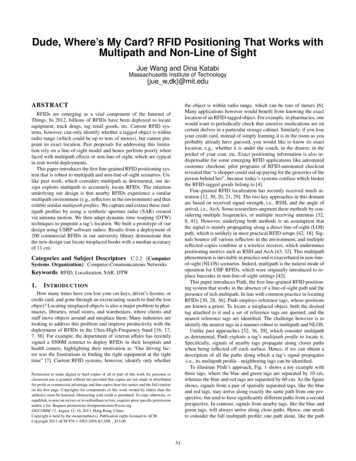
Left wallcompete to increase the range [6], and hence it is expected to continue growing over the coming years. Providing accurate positioninformation while keeping the range large will be a necessary andvaluable feature for RFID systems.Ref tagBeam StrengthRef tagRef tagNLOS3.0.3Right wallDesiredtagDesired tagRef tag0.20.1P IN I T OVERVIEWPinIt is a fine-grained UHF RFID localization system that canprovide a resolution on the order of a few to tens of centimeters,much smaller than the read range of UHF RFIDs.Following a common practice in RFID localization, PinIt leverages the ultra-low cost of UHF tags (5-10 cents each) to deploy a setof reference tags in the environment, e.g., reference tags in a librarycan be placed on the shelves of each rack. PinIt’s infrastructure alsoincludes a database which stores the IDs and 3-D positions of thereference tags. Further, PinIt works under the assumption that theobjects to be located are tagged with RFIDs, e.g., every book in alibrary can have a tag adhered to its spine. The association betweeneach object and its RFID is registered in PinIt’s database.To locate an object, at a high level PinIt goes through the following steps:0050100Spatial Angle (degree)Antenna Array(a) Multipath environment150(b) Multipath profilesFigure 3—Illustration of multipath profiles: (b) shows the threetags’ multipath profiles captured by the antenna array in (a). Thepeaks on the left correspond to the reflected paths off the left wall,and the peaks on the right correspond to the reflected paths off theright wall. The spatial angle positions of the peaks reveal that thedesired tag is closer to the green tag than the red one.when the beam direction is steered to around 140 , the reflectedpaths off the right wall are observed alone. Fig. 3(b) successfullycaptures the fact that the desired tag (blue) is spatially closer tothe green tag: positions of both peaks in the green and blue tags’curves are close to each other, whereas the red tag’s peak on theright has a 12 shift from the blue tag’s. This example demonstratesthe following observation: if two tags are close to each other inspace, the whole set of paths in their profiles should closely match.In other words, they should appear to be close overall from variousperspectives as revealed by their multipath profiles.Now we formally define an RFID’s multipath profile as a vector B(θ), where each element is the power of the RFID’s signalreceived in the beam at a direction θ [0 , 180 ]. Next we startby explaining how to compute B(θ) in a simplified scenario – ifwe were allowed a uniform linear antenna array. Then in §4.2, wepresent PinIt’s acquisition of B(θ) using a single moving antenna. PinIt queries the RFID tag attached to the object (i.e., desiredtag), as well as the reference tags. PinIt acquires a multipath profile of each queried tag based on itsreplies, using the technique in §4. By comparing and matching the desired tag’s multipath profilewith the reference tags’ as described in §5, PinIt identifies thenearest neighbors of the desired tag. Finally, based on the positions of these nearest neighbors, it estimates the desired tag’s position, locating the object.In large-scale deployments like libraries and pharmacies, therecan be a large number of reference tags. It is difficult and timeconsuming to query them all. In §6, we describe PinIt’s hierarchicalprotocol to pinpoint the position of the desired tag by graduallyzooming in to sub-regions.The next few sections elaborate on the above steps, providing thetechnical details.4.1Multipath Profile Acquisition Using Antenna ArrayAn array with K uniformly spaced antenna components is shownin Fig. 4. In order to obtain a narrow beam in the θ direction (i.e.,steer the beam to the direction identified by θ), the array projects thereceived signals at all of its antennas on the θ direction. This projection is done by multiplying the received signal at each antennaby a complex number (i.e., weight) in post-processing. Then the received signals are linearly combined with these complex weights,which aligns their phases [33]. Such an operation focuses the beamin the θ direction while minimizing signals in other directions, creating a spatial filter. Below, we establish the standard mathematicalformulation of linear array beamsteering.Let sk be the tag’s signal observed by the array’s kth antenna,k 0, ., K 1. w(k, θ) is the complex weight assigned to sk whensteering the beam to θ. λ is the wavelength. D is the length of theDis the position of the kth antenna. Then the powerarray. xk k K 1received in a beam in the θ direction is computed as:4.ACQUIRING A TAG ’ S M ULTIPATH P ROFILEAn RFID’s multipath profile is a collection of distinguishablepaths along which the tag’s signal travels to reach PinIt’s receiver.In this section, we focus on how to differentiate various paths andacquire such a profile for each tag.Copies of a signal arriving along different paths can be distinguished based on their different delays, like in radar systems. Suchan approach however would require ultra-wideband communication, which low-cost RFIDs do not support. Alternatively, multiple paths can be distinguished based on their directions, which isthe approach PinIt takes. In order to separate copies of the tag’ssignal arriving from different directions, we need to measure thepower coming from each direction alone. It is well-known that alarge phased antenna array can achieve this goal by forming a verynarrow beam and steering it around [40]. When steering its beamto a certain direction, the array essentially filters out power comingfrom all other directions, i.e., filtering out other paths.To visually understand this idea, let us again consider the simplesetup shown in Fig. 3(a) (same as in §1). Fig. 3(b) shows the powerreceived by an antenna array as a function of its steering angle. Thethree tags are not replying at the same time, i.e., their signals do notoverlap, so these curves are acquired individually. There are twopeaks in each tag’s power curve, corresponding to the two reflectedpaths of its signal. When the array steers its beam to around 40 ,it exclusively receives the tags’ signals reflected off the left wall;B(θ) K 1Xw(k, θ) · sk 2(1)k 02πw(k, θ) e j λ xk cos θ(2)w(k, θ), the weight assigned to antenna k when steering to θ, has aphase proportional to the distance between antenna k and the originprojected along θ, as Fig. 4 shows. We refer the reader to [33] forthe analysis and proof of this standard steering mechanism. At ahigh level, the weights in Eq. 2 project the received signals to θ bycompensating their phases according to the antennas’ positions.Steering its beam across 180 , the uniform linear array can acquire the multipa
software radios and evaluated it with a deployment of 200 com-mercial UHF RFIDs in our university library (Fig. 9). The tags are placed on 12 racks with a total of 60 shelves and separated by 15 cm. In every experiment, we tag a book and move it to a random shelf.


![[Concurso]Configuracion de The DUDE como Network](/img/10/concursoconfiguracion-de-the-dude-como-network-managment-system-comunidad-ryohnosuke-com.jpg)