Transcription
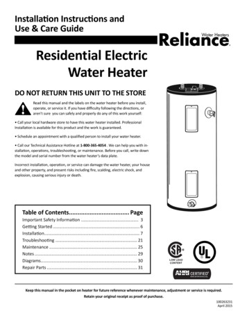
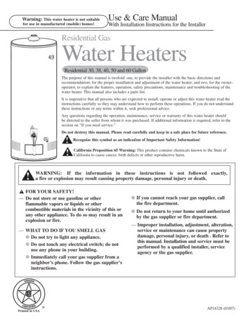
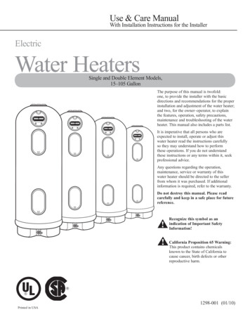
Use & Care ManualWith Installation Instructions for the InstallerElectricWater HeatersSingle and Double Element Models,15–105 GallonThe purpose of this manual is twofold:one, to provide the installer with the basicdirections and recommendations for the properinstallation and adjustment of the water heater;and two, for the owner–operator, to explainthe features, operation, safety precautions,maintenance and troubleshooting of the waterheater. This manual also includes a parts list. It is imperative that all persons who areexpected to install, operate or adjust thiswater heater read the instructions carefullyso they may understand how to performthese operations. If you do not understandthese instructions or any terms within it, seekprofessional advice.Any questions regarding the operation,maintenance, service or warranty of thiswater heater should be directed to the sellerfrom whom it was purchased. If additionalinformation is required, refer to the warranty.Do not destroy this manual. Please readcarefully and keep in a safe place for futurereference.!! Recognize this symbol as anindication of Important SafetyInformation! alifornia Proposition 65 Warning:CThis product contains chemicalsknown to the State of California tocause cancer, birth defects or otherreproductive harm. Printed in USA1298-001 (01/10)
Safety InformationSafety Precautions. . . . . . . 3, 4FOR YOUR RECORDSWrite the model, serial numbers, and installation details on theback cover of the manual.This information is located on the rating plate (silver label) on theunit.Staple sales slip or cancelled check here.Installation InstructionsLocation. . . . . . . . . . . . . . . . . . 5Proof of the original purchase date is needed to obtainservice under the warranty.Water Connections . . . . . . . . . 8Electrical Connections. . . . . 10Wiring Diagram. . . . . . . . . . 11READ THIS MANUALOperating InstructionsInside you will find many helpful hints on how to use and maintainyour water heater properly. Just a little preventive care on your partcan save you a great deal of time and money over the life of yourwater heater.Safety Controls . . . . . . . . . . 14Water Temperature . . . . . . . . 14You’ll find many answers to common problems in the Before YouCall For Service section. If you review our chart of TroubleshootingTips first, you may not need to call for service at all.READ THE SAFETY INFORMATIONCare and CleaningDraining. . . . . . . . . . . . . . . . 16Your safety and the safety of others are very important. Thereare many important safety messages in this manual and on yourappliance. Always read and obey all safety messages.Maintenance. . . . . . . . . . . . . 16!Extended Shut-Down. . . . . 16Troubleshooting TipsBefore You CallFor Service. . . . . . . . . . . . . . 17This is the safety alert symbol. Recognize this symbolas an indication of Important Safety Information!This symbol alerts you to potential hazards that cankill or hurt you and others.All safety messages will follow the safety alert symbol andeither the word “DANGER”, “WARNING”, “CAUTION” or“NOTICE”.These words mean:DANGERAn imminently hazardous situationthat will result in death or seriousinjury.A potentially hazardous situation thatcould result in death or serious injuryand/or damage to property.Replacement Parts. . . . . . 19, 20A potentially hazardous situation thatmay result in minor or moderateinjury.Element Replacement. . . . . 21Notice:!!Customer ServiceParts List. . . . . . . . . . . . . . . . 18Warranty. . . . . . . . . . . . . . . . . 222!WARNINGCAUTIONAttention is called to observe aspecified procedure or maintaina specific condition.
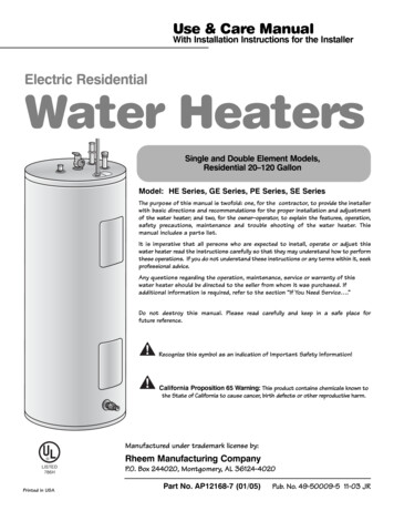
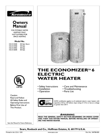
IMPORTANT SAFETY INFORMATION.READ ALL INSTRUCTIONS BEFORE USING.DANGER!water temperature settingSafety and energy conservation are factors to be considered when selecting the watertemperature setting of water heater’s thermostat. Water temperatures above 125 F (51 C)can cause severe burns or death from scalding. Be sure to read and follow the warningsoutlined on the label pictured below. This label is also located on the water heater nearthe thermostat access panel.Time/Temperature Relationship in Scalds!DANGERTemperatureTime To Produce a Serious Burn120 F (49 C)125 F (51 C)130 F (54 C)135 F (57 C)140 F (60 C)145 F (63 C)150 F (66 C)155 F (68 C)More than 5 minutes1½ to 2 minutesAbout 30 secondsAbout 10 secondsLess than 5 secondsLess than 3 secondsAbout 1½ secondsAbout 1 secondTable courtesy of Shriners Burn InstituteTESENOTICE: Mixing valves are available for reducing pointof use water temperature by mixing hot and cold waterin branch water lines. Contact a licensed plumber or thelocal plumbing authority for further information.Reset buttonRChildren, disabled and elderly areat highest risk of being scalded.See instruction manual beforesetting temperature at waterheater.Feel water before bathing orshowering.Temperature limiting valves areavailable, see manual.The temperature of the water in the heater isregulated by the adjustable surface mountedthermostat(s) located behind the jacket accesspanel(s). Dual element heaters have two thermostats.To comply with safety regulations the thermostat(s)were set at 120 F before the water heater wasshipped from the factory. Canadian models are setto 140 F (60 C).ESEWater temperature over 125 F cancause severe burns instantly ordeath from scalds.! DANGER: Households with small children, disabled,or elderly persons may require a 120 F (49 C) or lowerthermostat setting to prevent contact with “HOT” water.RBURNThe chart shown above may be used as a guidein determining the proper water temperature for yourhome.THOTThermostat dialpointer150 F(66 C)Thermostatprotectivecover90 F(32 C)125 F (52 C)TURN OFFPOWERBEFORESERVICINGThe illustration at the leftshows the temperatureadjustment dial usedfor setting the watertemperature.Refer to the OperatingInstructions in thismanual for detailedinstructions in how toadjust the thermostat(s).! DANGER: Hotter water increases the potential forHot Water SCALDS.3
IMPORTANT SAFETY INFORMATION.READ ALL INSTRUCTIONS BEFORE USING.WARNING!For your safety, the information in this manual must be followed to minimize the risk offire or explosion, electric shock, or to prevent property damage, personal injury, or loss oflife.Be sure to read and understand the entire Use and Care Manual before attemptingto install or operate this water heater. It may save you time and cost. Pay particularattention to the Safety Instructions. Failure to follow these warnings could result inserious bodily injury or death. Should you have problems understanding the instructionsin this manual, or have any questions, STOP, and get help from a qualified servicetechnician, or the local electric utility.FOR INSTALLATIONS IN THE STATE OF CALIFORNIACalifornia Law requires that residential water heaters must be braced, anchored orstrapped to resist falling or horizontal displacement due to earthquake motions. Forresidential water heaters up to 52 gallon capacity, a brochure with generic earthquakebracing instructions can be obtained from: Office of the State Architect, 1102 Q Street,Suite 5100, Sacramento, CA 95811 or you may call 916-445-8100 or ask a water heaterdealer.However, applicable local codes shall govern installation. For residential water heatersof a capacity greater than 52 gallons, consult the local building jurisdiction for acceptablebracing procedures.SAFETY PRECAUTIONSHave the installer show you the location of the circuit breaker and how to shut it off ifnecessary. Turn off the circuit breaker if the water heater has been subjected to overheating,fire, flood, physical damage or if the ECO (Emergency Cut Off) on the thermostat fails to shutoff.of your water heater unless it is specifically Read this manual entirely before installingrecommended in this manual. All otheror operating the water heater.servicing should be referred to a qualified Use this appliance only for its intendedtechnician.purpose as described in this Use and Care All replacement parts used on thisManual.product must be manufacturer authorized Be sure your appliance is properly installedcomponents.in accordance with local codes and theprovided installation instructions. Do not attempt to repair or replace any partRead and follow this Safety Informationcarefully.SAVE THESE INSTRUCTIONS4
Installing the water heater.Local Installation RegulationsThis water heater must be installed inaccordance with these instructions, localcodes, utility codes, utility companyrequirements or, in the absence of localcodes, the latest edition of the NationalElectrical Code. It is available from somelocal libraries or can be purchased fromthe National Fire Protection Association,Batterymarch Park, Quincy, MA 02269 asbooklet ANSI/NFPA 70.If the water heater is to be installed in arestaurant, or other location where NSFInternational listing is required, it mustbe weather sealed to the floor, a raisedbase, or on a shelf so that seepage cannotaccumulate under it; or elevated to provideat least (6) inches of clearance from thefloor.In order to meet NSF Internationalrequirements for Standard 5, the baseof the water heater must be sealed tothe floor to prevent seepage underneath.Apply a 3/8" bead of RTV Siliconecompletely around the floor edge of thebase of the tank.The location chosen for the water heater must take into consideration the following:LocationNOTICE: DO NOT usefittings on top of the unit ashandles or lift points.Locate the water heater in a clean dry areaas near as practical to the area of greatestheated water demand. Long un-insulatedhot water lines can waste energy andwater.Place the water heater in such a mannerthat the thermostat and element accesspanels can be removed to permit inspectionand servicing such as removal of elementsor checking controls.The water heater and water lines shouldbe protected from freezing 51051UnitCapacity(Imperial Gallons)1317253342637188Do not install the water heater in outdoor,unprotected areas or near any otherappliances where high temperatures arepresent, such as wood burning stoves,boilers, or furnaces. High temperaturescan warp or otherwise damage the nonmetallic construction of this water heater.Make certain the floor underneaththe water heater is strong enough tosufficiently support the weight of thewater heater once it is filled with water.Dimensions (Inches)Height 1 Diameter35 5/834 1/25365 1/266 3/447 1/462 5/870 1/470 3/421 5/823 1/221 5/821 5/823 1/228 1/428 1/428 1/430 1/4Shipping ApproximateWeightFull 7481348431521,028 Height includes factory installed Temperature and Pressure Relief Valve.5
Installing the water heater.Thermal ExpansionDetermine if a check valve exists in the inlet waterline. Check with your local water utility. It may havebeen installed in the cold water line as a separateback flow preventer, or it may be part of a pressurereducing valve, water meter or water softener. Acheck valve located in the cold water inlet line cancause what is referred to as a “closed water system”.A cold water inlet line with no check valve or backflow prevention device is referred to as an “open”water system.As water is heated, it expands in volume and createsan increase in the pressure within the water system.This action is referred to as “thermal expansion”.In an “open” water system, expanding water whichexceeds the capacity of the water heater flowsback into the city main where the pressure is easilydissipated.A “closed water system”, however, prevents theexpanding water from flowing back into the mainsupply line, and the result of “thermal expansion”can create a rapid and dangerous pressure increasein the water heater and system piping. This rapidpressure increase can quickly reach the safety settingof the relief valve, causing it to operate during eachheating cycle. Thermal expansion, and the resultingrapid and repeated expansion and contraction ofcomponents in the water heater and piping systemcan cause premature failure of the relief valve, andpossibly the heater itself. Replacing the relief valvewill not correct the problem!The suggested method of controlling thermalexpansion is to install an expansion tank in thecold water line between the water heater and thecheck valve (refer to the illustration on page 9). Theexpansion tank is designed with an air cushion builtin that compresses as the system pressure increases,thereby relieving the over pressure condition andeliminating the repeated operation of the relief valve.Other methods of controlling thermal expansion arealso available. Contact your installing contractor,water supplier or plumbing inspector for additionalinformation regarding this subject.Inspect Water HeaterInspect the water heater for possible damage. Check the markings on the rating plate of the water heater tobe certain the power supply corresponds to the water heater requirements.6
Temperature and Pressure Relief ValveA new combination temperature and pressure relief valve, complying with the Standard for ReliefValves and Automatic Gas Shut-Off Devices for Hot Water Supply Systems, ANSI Z21.22, is suppliedand must be installed in the opening provided and marked for the purpose on the water heater. Novalve of any type should be installed between the relief valve and the tank. Local codes shall govern theinstallation of relief valves.! WARNING: The pressurerating of the relief valve mustnot exceed 150 PSI, (1034KPA), the maximum workingpressure of the water heater asmarked on the rating plate.The BTUH rating of the relief valve mustnot be less than the input rating of thewater heater as indicated on the ratinglabel located on the front of the heater(1 watt 3.412 BTUH).Connect the outlet of the relief valveto a suitable open drain so that thedischarge water cannot contact liveelectrical parts or persons and to eliminatepotential water damage.Piping used should be of a type approvedfor hot water distribution. The dischargeline must be no smaller than the outlet ofthe valve and must pitch downward fromthe valve to allow complete drainage (bygravity) of the relief valve and dischargeline. The end of the discharge line shouldnot be threaded or concealed and shouldbe protected from freezing. No valve ofany type, restriction or reducer couplingshould be installed in the discharge line.Vacuum Relief ValveNOTICE: Do NOT removeor tamper with the vacuumrelief valve for any reason.Doing so will void themanufacturer’s warranty.The vacuum relief valve, which must beused when installing the water heater, isfactory installed.The cold water inlet has a vacuum reliefvalve connected to it. Certain conditionsin the field may produce a vacuum or negative pressure condition inside the waterheater’s tank. This negative pressure cancause the tank to fail. The vacuum reliefvalve provides a means to eliminate thenegative pressure or vacuum by admittingair into the tank to equalize the pressure.It is not recommended to pull a vacuum onthe unit.If a vacuum is pulled on the unit, referto the "To Fill the Water Heater" sectionto ensure the unit is full of water beforeoperating.7
Installing the water heater.Drain PanNOTICE: Auxiliarycatch pan MUSTconform to local codes.NOTICE: Water heatermust be centered indrain pan.The water heater should not belocated in an area where leakage ofthe tank or connections will result indamage to the area adjacent to it or tolower floors of the structure. Wheresuch areas cannot be avoided, it isrecommended that a suitable catchpan, adequately drained, be installedunder the water heater.Under no circumstance will themanufacturer be held liable for anywater damage in connection withthis water heater.Catch pan kits are available fromthe store where the water heaterwas purchased, or any water heaterdistributor.B Max 2″BA Diameter ofwater heaterplus 2″ min.ATo open drain, this line should be at least 3/4″ ID andpitched for proper drainage.Water Supply ConnectionsNOTICE: Do notattempt to turn anyfitting connected to thewater heater union hexnuts that are tightened.Doing so will damagethe water heater andvoid the manufacturer’swarranty.! WARNING: The tank mustbe full of water before heateris turned on. The water heaterwarranty does not coverdamage or failure resultingfrom operation with an emptyor partially empty tank.8Refer to the illustration on right forsuggested typical installation. Theinstallation of unions or flexiblecopper connectors is recommendedon the hot and cold water connectionsso that the water heater may beeasily disconnected for servicing ifnecessary. The HOT and COLD waterconnections are clearly marked andare 3/4″ NPT on all models. Install ashut-off valve in the cold water linenear the water heater.The cold water connection, hot waterconnection, and the temperatureand pressure relief valve may betemporarily disconnected from the unitto ease installation by loosening theunion hex nuts connecting the fittingsto the water heater. The connection ofthese parts to the unit use seal rings toform a water tight connection. Re-usethe rubber seal rings that are providedwith the heater when re-installingTo Fill the Water HeaterMake certain the drain valve is completelyclosed.Open the shut-off valve in the cold watersupply line.the components. Do NOT use pipesealant on this joint. Do NOT torquethe union hex nuts to over 35 ft-lbswhen reinstalling the components.Failure to properly reconnect thefittings provided with the water heaterwill void the manufacturer’s warranty.SOLDER WITH CARE!!! Ifsweat connections are used, do NOTapply heat directly to any componentdirectly connected to the waterheater. This includes the cold waterconnection, hot water connection,temperature and pressure relief valveand the drain valve. Assembliesshould be built to a minimum lengthof 12” before attaching to the waterheater to avoid damaging the unit.WARNING: Failure to follow theinstructions provided in this manualmay permanently damage the unit andvoid the manufacturer’s warranty.!Open each hot water faucet slowly toallow the air to vent from the waterheater and piping.A steady flow of water from the hot waterfaucet(s) indicates a full water heater.
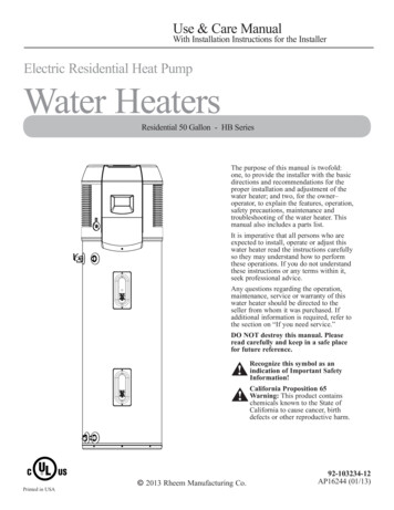
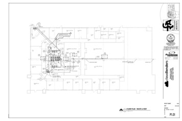
Typical InstallationTemperature & PressureRelief ValvePre-solder 12" minimumstub pipes before installingto unit.Support the relief valve drain pipeusing metal strapping or wirefastened to the structure overheadCold Inlet Shut OffHot Water OutletHeat Trap 6"MinimumSeal Ring(Inside nut)Hex Union Nut(Relief Valve)Top of Water Heater JunctionBoxThermal ExpansionTank (if required)See thermalexpansion sectionon page 6. Union(The addition of a union atthis point will help in thereplacement of the T & P ReliefValve should the need arise.)Drain Pipe -(3/4" minimum)No threads permittedon end of Drain Pipe.Drain Valve6” Maximum distance fromdrain pipe to suitable opendrain.Drain Pan9
Installing the water heater.Electrical Connections! CAUTION: The presenceof water in the piping andwater heater does not providesufficient conduction for aground. Non-metallic piping,dielectric unions, flexibleconnectors etc. can cause thewater heater to be electricallyisolated.A separate branch circuit with copperconductors, over current protective deviceand suitable disconnecting means must beprovided by a qualified electrician.All wiring must conform to local codesor latest edition of National ElectricalCode ANSI/NFPA 70.Canadian models must conform to localcodes or latest edition of CanadianElectrical Code.The water heater is completely wired tothe junction box inside jacket at the topfront of the water heater. An opening for1/2″ or 3/4″ electrical fitting is providedfor field wiring connections.The branch circuit wiring should includeeither: etallic conduit or metallicMsheathed cable approved for use as agrounding conductor and installedwith fittings approved for thepurpose. on-metallic sheathed
installation and adjustment of the water heater; and two, for the owner–operator, to explain the features, operation, safety precautions, maintenance and troubleshooting of the water heater. This manual also includes a parts list. It is imperative that all pe