Transcription
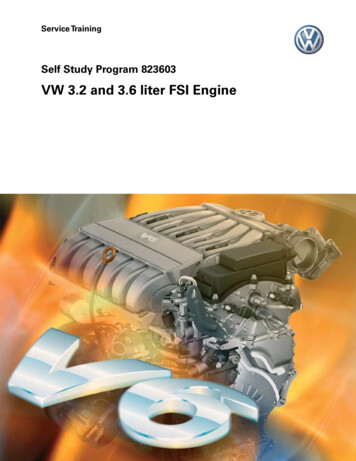
Service TrainingSelf-Study Program 822703Volkswagen 4.2L V8 FSI Engine
Volkswagen Group of America, Inc.Volkswagen AcademyPrinted in U.S.A.Printed 5/2008Course Number 822703 2008 Volkswagen Group of America, Inc.All rights reserved. All information contained inthis manual is based on the latest informationavailable at the time of printing and is subject tothe copyright and other intellectual property rightsof Volkswagen Group of America, Inc., its affiliatedcompanies and its licensors. All rights are reservedto make changes at any time without notice.No part of this document may be reproduced,stored in a retrieval system, or transmitted in anyform or by any means, electronic, mechanical,photocopying, recording or otherwise, nor may thesematerials be modified or reposted to other siteswithout the prior expressed written permission ofthe publisher.All requests for permission to copy and redistributeinformation should be referred to Volkswagen Groupof America, Inc.Always check Technical Bulletins and the latestelectronic repair information for information that maysupersede any information included in this booklet.Trademarks: All brand names and product namesused in this manual are trade names, service marks,trademarks, or registered trademarks; and are theproperty of their respective owners.
ContentsIntroduction . 2Engine Mechanical . 4Engine Management . 20Functional Diagram . 32Service . 36Knowledge Assessment . 37NoteThis Self-Study Program covers information onthe Volkswagen 4.2L V8 FSI Engine.This Self-Study Program is not a Repair Manual.This information will not be updated.Important!For testing, adjustment and repairprocedures, always refer to the latestelectronic service information.i
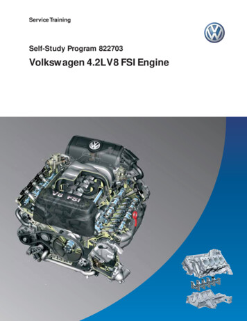
IntroductionTechnical FeaturesThe 4.2 Liter V8 4V FSI engine is the most recent example of the Fuel Straight Injection engines fromVolkswagen. It is the successor to the 4.2 Liter V8 5V engine and is used in the Touareg.The 2.0 Liter turbocharged FSI was the first engine introduced by VW with direct injection technology.Following its success, the 3.6 Liter V6 FSI and 4.2 Liter V8 4V FSI were introduced.– Bosch Motronic MED 9.1.1– Fuel Straight Injection (FSI)– Electronic Throttle (Electronic Pedal Control)– Two hot film mass airflow sensors– Electronically regulated cooling system– Adjustment of the variable intake manifold andintake manifold flap change-over by means of anelectric motor– Continuous inlet and exhaust camshaft timingadjustment– Two-piece cylinder block– Chain drives for camshafts and ancillary drivesmounted on the flywheel side of the engine– Spur gear drive for ancillary units– Secondary air injection system4.2L V8 FSI EngineS388 0032
IntroductionTechnical DataTorque lb ft (Nm)Power hp (kW)368 lb ft (500 Nm)402 hp (300 kW)332 lb ft (450 Nm)362 hp (270 kW)295 lb ft (400 Nm)322 hp (240 kW)258 lb ft (350 Nm)282 hp (210 kW)221 lb ft (300 Nm)241 hp (180 kW)184 lb ft (250 Nm)201 hp (150 kW)147 lb ft (200 Nm)160 hp (120 kW)111 lb ft (150 Nm)120 hp (90 kW)74 lb ft (100 Nm)80 hp (60 kW)37 lb ft (50 Nm)40 hp (30 kW)0001000 2000 3000 4000 5000 6000 7000 8000rpmS388 004Engine CodeBARType8 cylinders with 90 V angleDisplacement in254 cubic in (4163 cc)Bore in3.32 in (84.5 mm)Stroke in3.65 in (92.8 mm)Valves per Cylinder4Compression Ratio12.5 : 1Maximum Output350 hp (257 kW) at 6800 rpmMaximum Torque325 lb ft (440 Nm) at 3500 rpmEngine ManagementBosch Motronic MED 9.1.1FuelPremium plus unleaded RON 98 or premium unleaded RON 95Exhaust Gas Treatment4 catalytic converters, 4 O2 sensors, secondary air systemEmissions StandardLEV II3
Engine MechanicalChain DriveIn chain drive D, the crankshaft drives the drive chainsprocket for ancillary drives. This is used to drive thespur gear for the ancillary units.In the 4.2l V8 4V FSI engine, the camshafts andancillary units are driven by a total of four rollerchains on two levels. The chain drive is maintenancefree and reduces the over-all length of the engine.The crankshaft drives the two drive gears for thecamshaft timing chains via chain drive A. In turn,these two drive gears drive the camshaft adjustersfor the exhaust and intake camshafts via chain drivesB and C.The chains are tensioned by hydraulic springtensioners.Chain Drive AChain Drive BChain Drive CS388 005Chain Drive D4
Engine MechanicalAncillary Unit DriveThe ancillary units (engine coolant pump, powersteering pump and A/C compressor) are driven bythe crankshaft via chain drive D, a spur gear drive, agear module and four intermediate shafts.The gear module is used to adapt the rotationalspeed and therefore the delivery rate of the enginecoolant and oil pumps.Air Conditioner CompressorCoolant PumpS388 006Oil PumpGear ModulePower Steering Pump5
Engine MechanicalIntake SystemAs in the 4.2 Liter V8 5V engine used previously inthe Touareg, the fresh air intake system is designedwith two branches, therefore reducing pressurelosses.Both intake tracts are brought together upstream ofa common throttle valve module. Each intake track isequipped with a mass airflow sensor.4.2L V8 FSI Intake SystemThrottle Valve ModuleVariable Inlet ManifoldMass Air Flow(MAF) SensorG70Mass Air Flow(MAF) Sensor2 G246Intake Manifold FlapsS388 007Intake ManifoldThe two-stage variable intake manifold ismanufactured from die-cast magnesium.It houses the change-over flaps to vary the length ofthe intake runners as well as the flaps that changethe airflow path near the intake valves.Change-Over FlapS388 008Intake Manifold Flaps6
Engine MechanicalVariable Intake ManifoldSwitching between the long and short intakemanifold runners is determined by a performancemap of the Engine Control Module.– In the lower engine speed range, the long intakemanifold runners are used (torque position)– In the upper engine speed range, the short intakemanifold runners are used (output position)The change-over flaps are actuated by an electricmotor on command from the Engine ControlModule.The change-over flaps have sealing lips to ensurethat the long intake manifold remains leak-tight inthe torque position.S388 009Variable IntakeManifold RunnerMotor V183Intake Manifold RunnerPosition Sensor G336Selector Shaft withChange-Over FlapsIntake ManifoldFlapsIntake Manifold Flap Change-OverThe intake manifold flaps are installed in the twointake manifold lower sections. They are actuated,depending on load and engine speed, by an intakemanifold flap motor and two linkage systems.– At low load and engine speed, they are actuatedand close off the lower section of the intake ports.This results in cylindrical-shaped air flow into thecylinder.– At high load and engine speed, they are notactuated, and lie flush against the surface of theintake port in order to avoid flow losses.Due to emission-relevant reasons, the positionsof the intake manifold flaps are monitored by twointake manifold flap potentiometers.S388 010SeparatingPlateIntake FlapMotor V157Intake Manifold RunnerPosition Sensor 2 G5127
Engine MechanicalCylinder BlockCrankshaft DriveThe cylinder block is manufactured from analuminum-silicon alloy by means of low-pressuregravity die casting. It is characterized by highstrength, very low cylinder warming and goodthermal dissipation.The crankshaft is manufactured from high-qualitytempered steel, and is supported by five bearings.To obtain the narrowest cylinder webs possible,cylinder liners have been omitted.Forged pistons are used for reasons of strength. Thepiston crowns have been adapted to the combustionprocess involved in FSI technology, and support thecircular flow of air in the cylinder. The piston skirtsare coated with Ferrostan, which contains iron. Thisprevents direct contact between the pistons and thecylinder walls, reducing wear.The large ends of the connecting rods are crackedduring manufacture. This ensures a tight, precise fitof the cap after the bearing has been installed.Final cylinder bore surface machining is carried out ina three-stage honing and exposure process. Duringthis process, the aluminum is separated from thesurface and the silicon is exposed in the form ofextremely small and particularly hard particles. Thesefinally form the wear-resistant contact surface for thepistons and the piston rings.The ladder frame is manufactured from an aluminumsilicon alloy by means of die casting. Cast-in bearingcaps manufactured from cast iron with nodulargraphite reinforce the ladder frame and absorb themajority of the flow of force. Due to their thermalexpansion, which is lower than that of aluminum athigh temperatures, they limit main bearing clearance.CrackedConnecting RodPiston SkirtThe ladder frame design with bearing caps offershigh longitudinal and transverse stiffness.S388 012Cylinder BlockPiston CrownCrankshaftCast-InBearing CapLadder FrameS388 0118
Engine MechanicalCylinder HeadsCamshaft Adjustment SystemThe 4-valve cylinder heads are manufactured froman aluminum alloy. This material provides very goodthermal conductivity and high strength.The gas exchange processes in the combustionchamber has a significant influence on output,torque and exhaust gas emissions. The camshaftadjustment system allows these gas exchangeprocesses to be adapted to the engine’srequirements.– The separating plates for intake manifold flapchange-over are installed in the intake ports– The injectors are fitted on the intake side in thecylinder head– The high-pressure fuel pumps are driven by dualcams on the intake camshaftsCamshaft adjustment is carried out continuouslyby vane adjusters, and has a maximum of 42 . Theposition of the camshafts are detected by means offour Hall senders.– The cylinder head cover is made of plastic andcontains a labyrinth oil separatorWhen the engine is not running, the vane adjustersare locked using a spring-loaded locking pin.– The camshafts are fully-assembled (the camshaftlobes are mated to the camshaft by a hydroforming process) and are driven by chain– The exhaust valves are filled with sodium. Thisreduces the temperature at the valve by 212 F(100 C)CylinderHeadCoverThe intake camshafts are set to the “retarded”position and the exhaust camshafts to the“advanced” position. To achieve this, a return springis installed in the exhaust camshaft vane adjusters.CrankcaseVentilationSystemIntake AdjusterHallSenderS388 014High-Pressure FuelPump with FuelMetering ValveS388 013Fully AssembledCamshaftExhaust Adjuster withReturn Spring9
Engine MechanicalOil SupplyDuring development of the oil supply system,emphasis was placed on achieving the lowestpossible oil flow while providing sufficientlubrication.As a result, the camshaft adjusters and variousfriction bearings were optimized. This engine’s oilflow of 53 qt (50 l) per minute at 7000 rpm at atemperature of 248 F (120 C) is very low.The advantage is that the oil remains in the oil sumpfor a longer period of time, and that better waterand hydrocarbon (uncombusted fuel) degasificationis possible. Additionally, a smaller oil pump can beused. This results in reducing the necessary drivepower and therefore, lowering fuel consumption.A baffle plate in the area of the intake connectionensures that no oil, which has been worked into afoam by the oil pump, is drawn into the oil system.The oil is cooled by an oil-water heat exchanger.CylinderBank 1Chain TensionerOil Filter ModuleCylinderBank 2HydraulicCamshaftAdjustmentOil PressureControl ValveOil Cooler(Coolant)Oil Pump(Gear)Oil SumpUpperSectionS388 017Baffle Plate10Oil SumpLowerSection
Engine MechanicalOil PumpOil Filter ModuleThe oil pump is located inside the oil sump uppersection and is bolted to the ladder frame. Oil intakeis first through a base filter located on the suctionside of the pump. All engine lubrication points aresupplied from the pressure side of the oil circuit.The oil filter module is designed as a full-flow filter.It is located in the inner V of the engine and the filterelement can be easily replaced without special tools.CapPressureOil SideReturn fromthe EngineFilter ElementConsisting ofPolymer MatS388 019Base FilterSuction SideS388 020To theEngineCircuitFrom theOil PumpPressure Side11
Engine MechanicalCrankcase Breather and Ventilation SystemCrankcase Breather SystemCrankcase Ventilation SystemThe crankcase breather system is used to flush freshair through the crankcase. As a result, water vaporand low-boiling hydrocarbons are removed from thecrankcase and diverted back into the engine intakeair to be burned.Because of the crankcase ventilation system, theuncombusted hydrocarbons (blow-by gases) arereturned to the combustion process and do notescape into the outside air.The air is removed downstream of the air filter, andis guided into the inner V of the cylinder block by anon-return valve. A restrictor downstream of the nonreturn valve ensures that only the correct quantity offresh air is supplied to the crankcase.To minimize the oil contained in the blow-by gases,they are separated by a labyrinth oil separator in thecylinder head cover and a three-stage cyclonic microoil separator.In the cylinder head cover, the gas encountersimpact plates, where the larger oil droplets areseparated. The gases are then channeled by hoses tothe micro oil separator. Here, the smaller oil dropletsare separated off, preventing intake valve coking.The induction point downstream of the throttle valvemodule is integrated into the engine cooling circuit toprevent it from freezing.Cooling CircuitConnection forHeatingCrankcaseBreatherSystemVent LineS388 023Non-Return Valve(Crankcase BreatherSystem)Micro OilSeparator12PressureLimiting Valve
Engine MechanicalThree-Stage Cyclonic Micro Oil SeparatorThe quantity of uncombusted hydrocarbons and oil vapor is dependent on the engine load and speed. The oilmixed with unburned hydrocarbons is separated by a three-stage cyclonic micro oil separator.Because cyclonic oil separators only perform well in a low volumetric flow range, one, two or three cyclones arereleased in parallel depending on the quantity of gas.Low Engine Load/Speed — Low Gas FlowAt low engine load and speed, the gas flow is low.The gas flows past the control plunger into the firstcyclonic oil separator. Here, the oil still present inthe gas is pressed outwards by centrifugal force,adheres to the wall and drips into the oil collectionchamber.The oil collection chamber contains an oil drain valve,which is closed by the pressure in the crankcasewhen the engine is running. When the engine isswitched off, the valve opens and the collectedoil flows into the oil sump through a hose locatedbelow the level of the oil. The pressure controlvalve ensures a constant pressure level and goodcrankcase ventilation.From alveOil CollectionChamberTo theInductionPointDownstreamof theThrottleValveModuleS388 024Oil DrainValveIncreasing Engine Load/Speed — Increasing GasFlowControl PlungerShiftedAs the engine load and speed increases, so to doesthe flow of the blow-by gases. The higher the flow,the greater the force which acts on the controlplunger. The control plunger force overcomes thespring force and releases the access ducts to furthercyclones.S388 02613
Engine MechanicalBypass Valve Opens — Very High Gas FlowThe bypass valve ensures that the pressure in thecrankcase does not become excessive.BypassValveOpenGases FlowPast theCyclonesIf the pressure in the crankcase increases rapidly, forexample due to a jammed control plunger or pistonring flutter (may occur at high engine speeds andlow load), the cyclones are no longer able to copewith this pressure increase. The pressure continuesto rise and now opens the bypass valve. Part of theblow-by gases now flow past the cyclone and areguided to the intake manifold directly through thepressure control valve.S388 05014
Engine MechanicalEngine Cooling CircuitThe cooling system is designed as a longitudinalcooling system. The coolant flows in on the intakeside, through the cylinder head gasket and into thehead, where it flows out through the timing chaincover. Cylinder web cooling has been improved bydrilling coolant ducts with cross-sections into thewebs. Forced flow through these bores is ensuredwith the aid of specifically sealed water ducts.In addition, the engine is equipped with anelectronically controlled cooling system.– In the partial load range which is not critical withregards to engine knock, the coolant temperatureis regulated to 221 F (105 C). In the lower partialload range, the thermodynamic advantagesand reduced friction result in a fuel saving ofapproximately 1.5%.– In the full load range, the coolant temperature isregulated to 194 F (90 C) by the map-controlledengine cooling system thermostat. This createscooler combustion chambers and better cylindercharging with reduced knock tendency.Heating SystemHeat ExchangerRecirculationPump V55Engine Coolant Temperature(ECT) Sensor G62Expansion TankOil CoolerCoolant PumpMap ControlledEngine CoolingThermostat F265Engine CoolantTemperature (ECT) Sensor(on Radiator) G83AlternatorRadiatorS388 01615
Engine MechanicalFuel System– The fuel pressure of up to 102 psi (7 bar) in thelow-pressure fuel system is generated by anelectric transfer fuel pump, which is actuated bythe engine control module through Fuel PumpControl Module J538.The fuel system is a requirement-controlled fuelsystem. This means that both the electric transferfuel pump and the two high-pressure fuel pumpsonly deliver the amount of fuel required by theengine at that particular moment. As a result, theelectrical and mechanical power requirements arereduced and fuel consumption is lowered.– The fuel pressure of 363 psi (25 bar) to 1523psi (105 bar) in the high-pressure fuel system isgenerated by two mechanical high-pressure fuelpumps, each of which is driven via a dual cam bythe intake camshafts.The fuel system is sub-divided into a low-pressureand a high-pressure fuel system.To minimize fuel pressure pulsations, both highpressure fuel pumps deliver fuel into a commonfuel line to the fuel rails. In addition, the highpressure delivery has been designed so thatpressure impulses of the pumps are offset at thecommon rail.Cylinder Fuel Injectors1 through 4 N30-N33Fuel PressureSensor G247Fuel MeteringValve N290FuelRailFuel MeteringValve 2 N402PressureLimitingValve1740 psi(120 bar)Cylinder Fuel Injectors5 through 8 N83-N86Low FuelPressureSensor G410Fuel FilterIntegratedinto TankLeakage LineFuel Tank16S388 027
Engine MechanicalExhaust SystemThe exhaust system is a twin-branch design. Thismeans that each cylinder head has a separateexhaust tract.The exhaust manifolds are insulated sheet metalmanifolds with a gas-tight inner shell. This airgap insulation enables a compact design and fastheating. Additional heat shields are no longernecessary. The exhaust manifolds are secured to thecylinder heads using clamping flanges.The starter and main catalytic converter substratematerial is comprised of ceramic.Both exhaust tracts end in the front silencer. There,the sound waves overlap and noise emissionsdecrease. Two exhaust pipes lead from the frontsilencer to the rear silencer. Both exhaust pipes arerouted separately in the interior of the rear silencer.The exhaust gas flows into the outside air via twotailpipes.Two broadband oxygen sensors are installeddownstream of the exhaust manifolds and twooxygen sensors downstream of the pre-catalyticconverters.ExhaustManifoldwith Air-GapInsulationHeated OxygenSensor (HO2S)2 G108Heated OxygenSensor (HO2S) G39Oxygen Sensor (O2S) Behind Three WayCatalytic Converter (TWC) G13
Service Training Self-Study Program 822703 Volkswagen 4.2L V8 FSI Engine. Volkswagen Group of America, Inc. Volkswagen Academy Printed in U.S.A. Printed 5/2008 Course Number 822703 . Volkswagen. It is the successor