Transcription
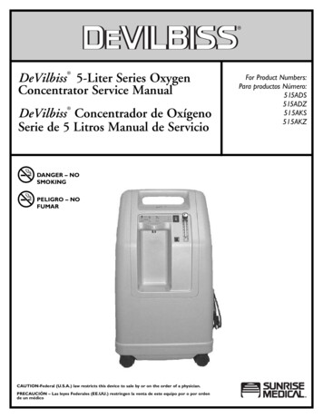
Service TrainingSelf-Study Program 824803The Volkswagen 2.0 LiterChain-Driven TSI Engine
Volkswagen Group of America, Inc.Volkswagen AcademyPrinted in U.S.A.Printed 5/2008Course Number 824803 2008 Volkswagen Group of America, Inc.All rights reserved. All information contained inthis manual is based on the latest informationavailable at the time of printing and is subject tothe copyright and other intellectual property rightsof Volkswagen Group of America, Inc., its affiliatedcompanies and its licensors. All rights are reservedto make changes at any time without notice.No part of this document may be reproduced,stored in a retrieval system, or transmitted in anyform or by any means, electronic, mechanical,photocopying, recording or otherwise, nor may thesematerials be modified or reposted to other siteswithout the prior expressed written permission ofthe publisher.All requests for permission to copy and redistributeinformation should be referred to Volkswagen Groupof America, Inc.Always check Technical Bulletins and the latestelectronic repair information for information that maysupersede any information included in this booklet.Trademarks: All brand names and product namesused in this manual are trade names, service marks,trademarks, or registered trademarks; and are theproperty of their respective owners.
ContentsIntroduction . 1Engine Mechanicals. 3Lubrication System . 20Crankcase Ventilation System . 25Cooling System . 27Air Intake System . 30Fuel System. 36Exhaust System . 43Engine Management System . 44Service . 48Knowledge Assessment . 51NoteThis Self-Study Program covers information onthe Volkswagen 2.0 Liter Chain-Driven TSI Engine.This Self-Study Program is not a Repair Manual.This information will not be updated.Important!For testing, adjustment and repairprocedures, always refer to the latestelectronic service information.i
Page intentionally left blank
IntroductionTechnical DescriptionFour Cylinder, Four Valve, TSI TurbochargedGasoline EngineEngine BlockEngine Management– Cast iron crankcase– MED 17.5 engine control module– Balancer shafts in crankcase– Hot-film air mass flow with integral temperaturesensor– Forged steel crankshaft– Sump-mounted oil pump — chain-driven bycrankshaft– Timing gear chain — front end of engine– Throttle valve with contactless sensor– Map-controlled ignition with cylinder-selective,digital knock control– Balancer — chain-driven at front end of engine– Single-spark ignition coilsCylinder HeadTurbocharging– 4-valve cylinder head– Integral exhaust turbocharger– 1 INA intake camshaft adjuster– Charge-air coolerIntake Manifold– Electrical wastegate valve– Tumble flapFuel Supply– Demand controlled on low and high-pressure ends– Multi-port high-pressure injector– Boost pressure control with overpressureExhaust– Single-chamber exhaust system with closecoupled pre-catalystCombustion Process– Fuel straight injection1
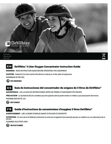
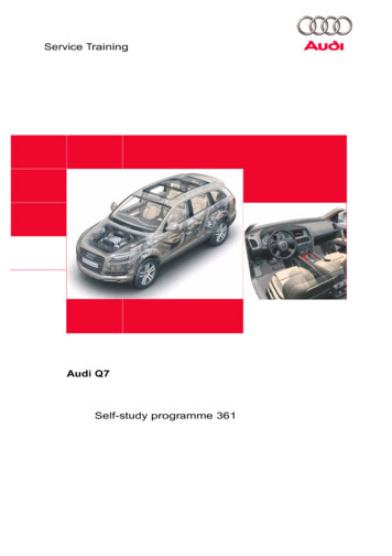
Introduction2.0L Chain-Driven TSI Engine201 (150)265 (360)243 (330)220 (300)161 (120)200 (270)177 (240)121 (90)155 (210)133 (180)80 (60)110 (150)88 (120)67 (90)40 (30)44 (60)22 (30)0001000200030004000500060007000Engine speed in RPMSpecificationsEngine CodeType of EngineDisplacement121 cu in (1984 cm3)Maximum Power200 hp (147 kW) at 5100 - 6000 rpmMaximum Torque206 lb ft (280 Nm) at 1700 - 5000 rpmNumber of Valves Per Cylinder4Bore3.2 in (82.5 mm)Stroke3.7 in (92.8 mm)Compression RatioFiring OrderEngine WeightEngine ManagementFuel GradeExhaust Emission Standard2CCTA - CBFAInline 4-Cylinder TSI Engine9.6 : 11-3-4-2317 lb (144 kg)Bosch MED 17.595/91 RONULEV (CCTA) - SULEV (CBFA)
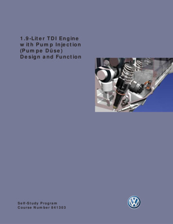
Engine MechanicalsCylinder BlockThe cylinder block has a closed-deck configurationand is made of cast iron. It houses the five-bearingcrankshaft assembly and the two balancer shafts.The undersides of the pistons are cooled by engineoil supplied by spray jets mounted on the cylinderblock.The housing for mounting the chain drives isintegrated in the block. The cylinder liners arefinished in a three-stage fluid jet honing process.The cylinder block is sealed on the transmission sideby a sealing flange and gasket.3
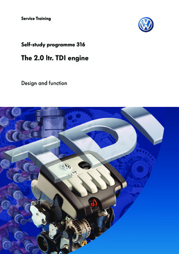
Engine MechanicalsOil PanThe oil pan consists of two sections.The upper section is made of an aluminum alloy(AlSi12Cu) and reinforces the crankcase through abedplate effect. It also houses the oil pump.The upper section is bolted to the crankcase andsealed with a liquid sealant.The bottom section is made of sheet steel (deepdrawn, punched, and catalytically coated). It housesOil Level Sensor G12 and the drain plug.The bottom section is bolted to the upper sectionand sealed with a liquid sealant.The oil pan has an integral honeycomb insert madeof polyamide to prevent oil churning when thevehicle is driven aggressively.Aluminum Alloy OilPan Top SectionPolyamideHoneycombInsertStamped Steel Oil PanBottom Section4
Engine MechanicalsCrankshaftThe five main bearing crankshaft is made of forgedsteel and induction hardened. Optimal balancing isachieved by using eight counterweights.The crankshaft main bearings are a two componenttype. Axial play of the crankshaft is controlled bythrust washers at the middle support bearing.To additionally reinforce the crankshaft assembly,three inner main bearing caps are cross-bolted to thecylinder block.Bronze bushings are press-fit into the smalltrapezoidal upper end of the connecting rods.Trapezoidal Connecting Rod (Small End)Material:36MnVS4Length:5.82 in (148 mm)Big-End Bearing:1.88 in (47.8 mm)Small-End Bearing:0.82 in (21 mm)The lower end of the connecting rods are cracked toensure a precision fit and reduce movement of thebearing cap under load.The upper and lower bearing shells of the connectingrod are not identical in composition. The upperbearing shell is a two-component compositebearing while the lower shell is a three-componentcomposite bearing.PistonWrist PinWrist PinRetaining ClipBronze ConnectingRod BushingTrapezoidalShaped Small Endof Connecting RodConnectingRod UpperBearing ShellMain Bearing CapConnectingRod CapCross-Bolted MainBearing Caps and Bolts5
Engine MechanicalsGears are coded forassembly — they can onlybe installed one wayVibration DamperChain SprocketCenter BoltSpur Gear DriveThe chain drive sprocket is mounted to thecrankshaft face and driven by a spur gear forged inthe crankshaft. The other end of the chain sprocketalso has a spur gear surface which drives thevibration damper. This method of joining allows hightorque to be transmitted to the chain sprocket andvibration damper while keeping the diameter of thecomponents small. This allows better sealing by theradial shaft seal at the vibration damper hub. Specialtools are required during disassembly/assembly ofthese components to prevent damage to the gears.6On the transmission side of the engine, a dualmass flywheel or torque converter (depending ontransmission) is mounted to the crankshaft witheight bolts.
Engine MechanicalsPistonsThe pistons are specially designed for the TSI enginewith a cast-in ring land for the upper piston ring.Coated skirts are used to help reduce frictionallosses. The upper piston ring is rectangular, thesecond piston ring is a taper-faced ring, and the oilscraper ring is a beveled ring with expander.The 31CrMoV wrist pins are held in place by snaprings. The bottom side of the pistons are cooled byengine oil from spray jets mounted on the cylinderblock.7
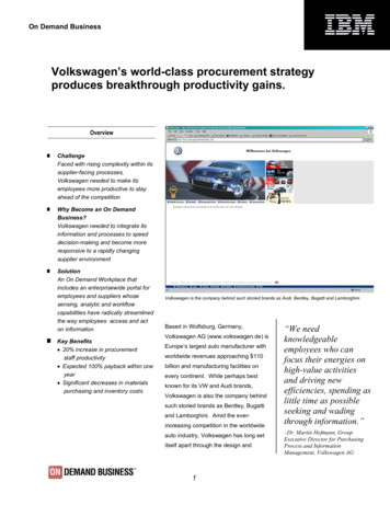
Engine MechanicalsCylinder HeadLMKNJOPIHGQFREDCSTBA8
Engine MechanicalsThe 4-valve cylinder head is cast from aluminumalloy. Intake and exhaust valves are actuated by rollercam followers supported by hydraulic valve lifters.The cylinder head cover adds support by acting as aladder frame and does not have to be disassembledto remove the cylinder head.The intake and exhaust camshafts are chain-driven.The diagonal opening and sealing face simplifiesdrive chain installation.The variable timing of the intake camshaft isaccomplished through the INA camshaft adjustmentsystem (page 11).Features– Crossflow cylinder head made of ASi10Mg– Single valve spring made of steel– Three-layer metal head gasket.– Roller cam followers running in needle bearings,hydraulic valve clearance adjustment– Intake ports divided by baffle plate– Cylinder head cover made of AlSi9Cu3 withintegrated ladder frame, bolted to cylinder headand sealed with liquid sealant– Intake valve: solid-stem valve, chrome-plated withreinforced seat– Exhaust valve: sodium filled hollow-stem valve,chrome-plated and tempered with reinforced seat– Hydro-formed, assembled intake camshaft withvariable valve timing, dwell angle 190 , valve lift10.7 mm– Hydro-formed, assembled exhaust camshaft withpress-fit drive gear, dwell angle 180 , valve lift8 mm– INA Camshaft Adjuster, timing range 60 crankangle, basic position is locked in “retard” (enginenot running)LegendACheck valveKCylinder head coverBSealing end capLCylinder head cover screwCExhaust valveMScrew plugDIntake valveNSealing end capEValve stem sealOHydraulic valve clearance adjusterFValve springPRoller cam followerGValve spring retainerQDowel pinHValve keeperRCylinder head bolt with washerIExhaust camshaftSExhaust manifold locating pinJIntake camshaft with INA adjusterTExhaust manifold stud9
Engine MechanicalsBearing BridgeA die-cast aluminum bearing bridge mounted at thefront of the cylinder head has the following tasks:– Supporting the camshafts– Supplying pressurized oil to camshaft bearings– Supplying pressurized oil to the camshaft adjuster– Controlling axial movement of camshafts– Mounting point for Camshaft Adjustment Valve 1N205Die-Cast AluminumBearing Bridge10The bearing bridge also serves to connect the two oilgalleries of the cylinder head. A check valve and filterscreen are integrated in the pressurized oil duct tothe INA camshaft adjuster.
Engine MechanicalsINA Camshaft Adjustment SystemThe 2.0L TSI engine uses a hydraulic vane celladjuster on the intake camshaft to affect valvetiming. Only the intake camshaft has variablyadjusted timing on this engine. Oil pressure for thistask is provided by the engine oil pump.The variable camshaft adjuster provides anadjustment range of 60 crank angle. The camshaftis locked in the retard position at engine shut-off.This function is performed by a spring-loaded lockingpin. The camshaft is released when the engine oilpressure exceeds 7.25 psi (0.5 bar).The rotor of the vane cell adjuster is welded to theintake camshaft. The 4/3-way central valve requiredfor adjuster control is integrated in the camshaft.Intake camshaft timing is map-controlled by theengine control module. The goals are to improveengine power, enhance running smoothness, andreduce emissions (through internal exhaust gasrecirculation).FunctionPressurized oil flows to the central valve via thecamshaft bearing through bores in the camshaft.From here, depending on adjustment requirements,the oil flows through additional bores in the camshaftto one of the chambers in the adjuster.StatorCover4/3-WayCentral ValveVane with SpringLow-FrictionBearingCamshaftAdjustmentValve 1 N205Locking PinArmatureLocking SpringShaft with BallRotorWindingCoil ElementCamshaft with Boresfor Hydraulic Control11
Engine MechanicalsValve TimingJ623G70G28N205J271G40G17LegendG17Engine Coolant Temperature SensorJ271Motronic ECM Power Supply RelayG40Camshaft Position SensorJ623Motronic Engine Control ModuleG28Engine Speed SensorN205Camshaft Adjustment Valve 1G70Mass Air Flow SensorThe valve is activated electrically via CamshaftAdjustment Valve 1 N205.When activated by a PWM signal, the solenoidproduces a variable magnetic field. Depending onthe strength of the magnetic field, the shaft withball is shifted towards the camshaft axis of rotation.This, in turn, displaces the 4/3-way central valve andallows the oil to flow to the corresponding chamber.12The new design has many advantages. It providesa very high adjustment rate capability even inunfavorable conditions such as cold starts or high oiltemperatures during engine idling.
Engine MechanicalsChain DriveAll three chains of the 2.0L engine are driven directlyby the chain sprocket mounted to the crankshaft.The chains are arranged in three planes (levels).– 1st Plane - Balance Shaft Drive– 2nd Plane - Camshaft Drive– 3rd Plane - Oil Pump DriveGear chains (as opposed to roller chains) are used inall three planes. They are 1/4 inch gear chains whosetension is controlled by four tension plates and fiveguide plates.Gear chains are more wear resistant and produceless noise than roller chains. The amount of spacerequired for a given power transmission capacity isless than that of a timing belt or roller chain.Gear chains are highly flexible in applicationbecause their width can be adapted for any powerrequirement by selecting the number of platesaccordingly. They have an efficiency of approximately99%.Intake Camshaftwith INA AdjusterOil PumpDriveBalance ShaftDrive Gear13
Engine Mechanicals1st Plane — Balance Shaft DriveTwo cylinder block housed balance shafts are usedto counteract unwanted vibration at engine speedsabove 4000 rpm from being transmitted to the carbody.The balance shafts run at twice the engine speed inopposite direction from one another. The directionof the second shaft is reversed by an idler gear. Thehorizontally staggered arrangement of the balanceshafts also helps reduce vibration.Chain lubrication is provided by oil returning from thecylinder head. Oil is collected and distributed to thechain by a separate lubrication channel.Mounting the balance shafts in the cylinder block hasthe following advantages:– The cylinder block provides higher rigidity– Oil foaming is eliminated by moving the rotatingparts away from the oil sumpThe balance shafts are made from spheroidalgraphite cast iron and run in three bearings.Balance ShaftsGuide RailHydraulic ChainTensionerIdler GearTensioning RailSlide RailChain Sprocket14
Engine MechanicalsBalance Shaft LayoutThe balance shaft is mounted in a plastic pipe. Thisprevents oil returning from the cylinder head fromchurning and foaming from direct contact with thebalance shaft.The oil return channel from the cylinder head islocated on the exhaust side of the cylinder block.Return oil flows through the balance shaft housing.Oil Return Channelfrom Cylinder HeadPlastic PipeOil Return LineIdler GearHelical BalanceShaft Drive Gear15
Engine Mechanicals2nd Plane — Camshaft DriveThe camshafts are driven by a chain positioned onthe second level. Tensioning is accomplished by ahydraulic tensioner. The tensioner can be accessedthrough a service opening. This allows the timingchain to be detached after removing the cylinderhead without having to remove the engine timingcover.Chain Tensionerwith Rig PinSlide Rail,Timing GearChain Sprocket, INAIntake Camshaft AdjusterChain Sprocket,Exhaust CamshaftCollar Bolt,Tensioning RailsGuide Rail,Timing GearTensioning Rail,Timing GearBalance Shaft Gear,Exhaust Side of EngineBalance Shaft Gear,Intake Side of EngineHydraulic Tensioner,Camshaft Chain DriveTensioning RailBalance ShaftChain TensionerSlide RailCollar Bolt,Tensioning RailChain SprocketTensioning Rail,Oil PumpChain, Oil PumpChain Sprocket,Oil Pump16
Engine Mechanicals3rd Plane — Oil Pump DriveThe chain drive for the oil pump is located in the thirdplane. A polyamide slide rail is used in this drive tolocate and tension the chain. The tension is producedby a mechanical spring.A hydraulically damped system is not needed dueto the low dynamic load. The chain is lubricated byreturn oil or by the oil in the oil pan.Drive SprocketAttached toCrankshaft forOil PumpSlide RailOil FilterScreenOil PumpPressureRegulating ValveTensioning Spring17
Engine MechanicalsEach drive chain has a special dark link. The darklinks are only on one side of the drive chain facingout from the engine block. For the adjustment of thecamshaft drive, the markings on the chain sprocketsmust align with the dark links of the chain.However, to bring the camshaft drive gears intoalignment with TDC by rotating the crankshaftrequires approximately 166 revolutions of thecrankshaft. Therefore, during repairs when the drivechains must be removed, it is acceptable that thetechnician use the dark links as a guide and make hisown markings on the sprockets.Please refer to the appropriate repair information forcomplete details.18
Engine MechanicalsAlternator/AC Compressor DriveA subframe supports both the alternator and airconditioning compressor. They are driven by apoly-vee belt which is tensioned by a adedBelt TensionerAir ConditionerCompressor19
Lubrication SystemLubrication System 232425262728ScreenOil pump, chain-drivenCold start valvePressure regulating valveCheck valve, integrated into oil pumpWater-oil heat exchangerCheck valve, integrated into oil pumpOil cleanerOil drain valveOil Pressure Switch F1Spray jets with integrated valvesOil screenChain tensionerChain tensionerGear lubricationCoarse oil mist separatorNon-return valve, integrated into cylinder headOil screenFlow restrictorLubrication of high-pressure fuel pump camFine oil mist separatorOil screenCheck valve, integrated into bearing bridgeMulti-directional regulating valve for camshaft adjusterCamshaft Adjustment Valve 1 N205Oil Level Thermal Sensor G266Vacuum pumpTurbochargerA242325A22Bearing Bridge76178109Subframe16Oil Separator15522643120Oil Pan
Lubrication System21AAAAB BB BB BB B27A18 19Vacuum PumpB BB BB BB BAAAAA Camshaft bearingB Support elementC Balance shaft bearingD Connecting rodE Main bearingCylinder HeadLow-Pressure Circuit1413CD28C12DCD12EE1112CDHigh-Pressure CircuitE1112CE11E11CCylinder Crankcase21
Lubrication SystemOil PumpThe external gear oil pump is housed in the oil pantop section and is chain-driven by the crankshaft.Excessively high oil pressures can occur at high oilviscosity levels during cold starting.The oil pressure is controlled inside the pump bya control spring and piston. The system is alsoprotected against overpressure by a spring loadedvalve ball (cold start valve).CoverDriveShaftBushingSteel BallCompression SpringEnd CapPistonCompression SpringStop22External OilPump GearsHousingChainSprocket
Lubrication SystemOil Filter and CoolerThe oil filter and oil cooler bracket are integrated in asubframe. It also houses the oil pressure switch andthe tensioner for the belt drive.The oil filter cartridge is accessible from above foreasy servicing. To prevent oil spillage when changingthe filter, a breech pin opens as the filter is removed.This allows the oil to flow back into the oil pan.Oil FilterOil CoolerOil FilterModule Bracket23
Lubrication SystemOil FilterCartridgeNon-ReturnValveOil Flowto EngineBreech PinOil SealsReturn Line to Oil PanClosed in this PositionNon-ReturnValve ClosedSleeve Integratedinto Oil FilterBreech Pin ResettingRange Allowing DirectReturn To Oil PanDirect Returnto Oil Pan24Oil Feed fromOil CoolerOil Cooler
Crankcase Ventilation SystemSystem OverviewA primary oil separator is installed on the cylinderblock just below the engine coolant pump. A baffleplate in the oil pan upper section prevents engineoil from being drawn out of the sump at
This Self-Study Program covers information on the Volkswagen 2.0 Liter Chain-Driven TSI Engine. This Self-Study Program is not a Repair Manual. This information will not be updated. For testing, adjustment and repair procedures, always refer to the latest e