Transcription
Service TrainingSelf Study Program 823603VW 3.2 and 3.6 liter FSI Engine
Volkswagen of America, Inc.Volkswagen AcademyPrinted in U.S.A.Printed 10/2006Course Number 823603 2006 Volkswagen of America, Inc.All rights reserved. All information contained in this manual isbased on the latest information available at the time of printingand is subject to the copyright and other intellectual propertyrights of Volkswagen of America, Inc., its affiliated companiesand its licensors. All rights are reserved to make changes atany time without notice. No part of this document may bereproduced, stored in a retrieval system, or transmitted in anyform or by any means, electronic, mechanical, photocopying,recording or otherwise, nor may these materials be modifiedor reposted to other sites without the prior expressed writtenpermission of the publisher.All requests for permission to copy and redistributeinformation should be referred to Volkswagen of America,Inc.Always check Technical Bulletins and the latest electronicrepair information for information that may supersede anyinformation included in this booklet.Trademarks: All brand names and product names used inthis manual are trade names, service marks, trademarks,or registered trademarks; and are the property of theirrespective owners.
ContentsOverview . . . . . . . . . . . . . . . . . . . . . . . . . . . . . . . . . . . . . . . . . . . . . . . . . . . 1Basics. . . . . . . . . . . . . . . . . . . . . . . . . . . . . . . . . . . . . . . . . . . . . . . . . . . . . . 4Engine Mechanics. . . . . . . . . . . . . . . . . . . . . . . . . . . . . . . . . . . . . . . . . . . 15Engine Management. . . . . . . . . . . . . . . . . . . . . . . . . . . . . . . . . . . . . . . . . 40Operating Diagrams . . . . . . . . . . . . . . . . . . . . . . . . . . . . . . . . . . . . . . . . . 59Service. . . . . . . . . . . . . . . . . . . . . . . . . . . . . . . . . . . . . . . . . . . . . . . . . . . . 65Knowledge Assessment. . . . . . . . . . . . . . . . . . . . . . . . . . . . . . . . . . . . . . 67NoteThis Self-Study Program provides informationregarding the design and function of newmodels.This Self-Study Program is not a Repair Manual.Important!This information will not be updated.For maintenance and repair procedures,always refer to the latest electronicservice information.iii
Page intentionally left blank
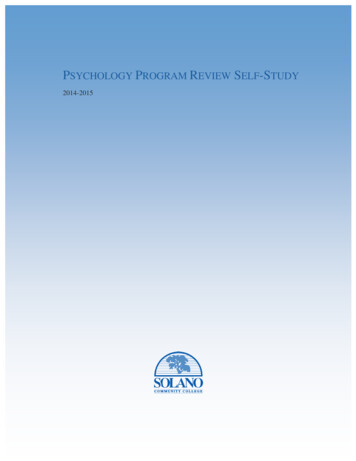
OverviewThe 3.2L and the 3.6L V6 FSI engines belong tothe VR family of engines. Their reduced V-angle,compared with a traditional V-engine, gives them anextremely compact and space-saving design.The VR engines have a long history at Volkswagen.The VR success began in 1992 with the start ofproduction of the 2.8L VR6 engine. In 2002, theVR6 was converted to four-valve technology. In 2003the capacity of the VR6 was increased to 3.2 liters,resulting in a power increase of up to 250 hp. Then,in 2006, the capacity was increased to 3.6 liters,resulting in a power increase of up to 280 hp.OverviewThis self-study program is designed for use in theVolkswagen Group, and therefore does not addressthe application of the engine in a specific vehicle.If reference is made to a particular vehicle, this isintended only as an example, to describe design,operation or to help better understand this manual.The VR engines are highly suitable for a broad rangeof applications due to their compact design.S360 371
OverviewS360 203The new 3.2L and 3.6L V6 FSI engines are thenewest representatives of the VR engine series.Special Features of both Engines: Compact size FSI direct gasoline injectionThe displacement was increased to 3.2 liters or3.6 liters, combined with the switch to the FSItechnology. This yields a noticeable increase in powerand torque compared with the previous engines.The 3.6L engine has a maximum rated power of280 hp (206 kW) and produces a maximum torque of265 lb.fts (360 Nm). Four-valve technology with roller rocker arms Internal exhaust gas recirculation Single-piece variable-length intake manifold madeof plastic Cast iron crankcase Chain drive located on the transmission side withintegral drive for the high-pressure fuel pump Continuously variable intake and exhaustcamshaftsThe use of FSI direct fuel injection technology makesit possible to meet current Low Emission Vehicle(LEV2) emission standards.
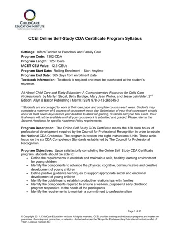
OverviewTechnical Data for the 3.2L V6 EngineConstructionDisplacement6 cylinders VR Engine193.3 cu.in (3168 cm3)Bore3.4 in (86 mm)Stroke3.58 in (90.9 mm)V Angle10.6 Valves per cylinder4Compression ratio12:1Max Output250 hp (184 kW) @ 6250 rpmMax Torque243 lbs.ft (330 Nm) @ 27503750 rpmEngine managementMotronic MED 9.1Exhaust emissioncontrolThree-way catalytic converterswith O2 sensorEmission standardLEV2Torque-power ower in hpTorque in lb.ftTechnical Data for the 3.6L V6 FSI EngineConstructionDisplacement6 cylinders VR Engine219.5 cu.in (3597 cm3)Bore3.5 in (89 mm)Stroke3.8 in (96.4 mm)V Angle10.6 Valves per cylinder4S360 116Torque-power Curve250250200225Compression ratio12:1Max Output280 hp (206 kW) @ 6200 rpm200Max Torque265 lbs.ft (360 Nm) @ 25005000 rpm175Engine managementMotronic MED 9.1Exhaust emissioncontrolThree-way catalytic converterswith O2 sensorEmission standardLEV21501001505012520004000Power in hpTorque in lb.ft6000S360 115
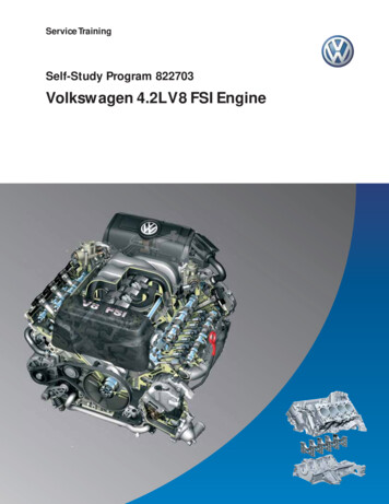
BasicsBasicsThe Variable Intake ManifoldThe variable intake manifold design increases lowrpm torque and high rpm power by taking advantageof the self-charging or “ram effect” that exists atsome engine speeds.By “tuning” the intake manifold air duct length,engineers can produce this ram effect for a given rpmrange. A manifold that has two different lengths of airducts can produce the ram effect over a broader rpmrange.Instead of using high velocity air flow in a longnarrow manifold duct to ram more air into an engineat low rpm and then opening a short, large diameterduct for high rpm, the 3.2 and 3.6-liter V6 enginestake advantage of the pressure wave created bythe pressure differential that exists between thecombustion chamber and the intake manifold.All air enters the intake manifold plenum and torqueport, then is drawn down the long intake ducts tothe cylinders.The 3.2 and 3.6-liter V6 engines use two lengths ofair ducts but not in the same way as the dual pathmanifolds used on other engines.Intake Manifold PlenumTorque PortChange-Over BarrelPerformance PortS360 370Vacuum Motor
BasicsA second plenum called the performance port,which is attached to a set of short manifold ducts,joins the long intake ducts near the cylinder head. Aperformance port valve, similar in design to a throttlevalve, separates the performance port from the shortducts.Note that the performance port does not have anypassage to the intake manifold other than throughthe performance port valve. It does not have accessto the torque port and does not admit any more airPerformance Port Valve OpenTorque Portinto the cylinders than what is already drawn downthe long intake ducts.At engine speeds below 900 rpm the performanceport is open for idling. The performance port valve isactuated. At engine speeds between 900 rpm and4100 rpm, the performance port is closed and theengine produces its maximum low end torque (theperformance port valve is not actuated).At engine speeds above 4100 rpm the performanceport is open (the performance port valve is actuated).Performance Port Valve ClosedPerformance PortS360 353Performance Port Valve OpenS360 352Torque PortPerformance PortS360 354Performance Port Valve CloseS360 351
BasicsPerformance Port Valve ActuationIntake manifold change-over is engine speeddependent. The Motronic Engine Control ModuleJ220 activates the Intake Manifold Change-OverValve N156, which supplies vacuum to the vacuumsolenoid that operates the performance port valve.A vacuum reservoir with non-return valve is usedto store a vacuum supply for the performance valveoperation. This is necessary as manifold vacuummay be insufficient to actuate the vacuum solenoidat high engine speeds.Performance Port Valve (Open)To Performance PortVacuum SolenoidFrom Torque PortTo Intake ValveSignal from MotronicEngine ControlModule J220Intake ManifoldChange-Over ValveN156Non-Return ValveTo Fuel Pressure RegulatorS360 355Vacuum Reservoir
BasicsPrinciples of Variable ResonanceIntake Manifold OperationAfter combustion has taken place in a cylinder,there is a pressure differential between the cylindercombustion chamber and the intake manifold. Whenthe intake valves open, an intake wave forms in theintake manifold. This low pressure wave moves fromthe intake valve ports toward the torque port at thespeed of sound.Performance Port Valve ClosedTorque PortPerformance PortIntake Valve ClosingS360 356The open end of the intake duct at the torque porthas the same effect on the intake wave as a solidwall has on a ball. The wave is reflected back towardthe intake valve ports in the form of a high pressurewave.Reflection PointPerformance Port Valve ClosedIntake Valve ClosingS360 357
BasicsAt an optimal intake manifold length, the maximumpressure reaches the intake valve ports shortlybefore the valves close. By this time the pistonhas started back up the cylinder, compressing theair/fuel mixture.The pressure wave forces more air into the cylinderagainst this rising compression pressure, filling thecylinder with more air/ fuel mixture than would bepossible from just the piston moving downward onthe intake stroke alone. This adds to what is calledself-charging or “ram effect.”Performance Port Valve ClosedIntake Valve ClosingS360 358Pressure WavePerformance Port Valve ClosedAs engine speed increases, the high pressure wavewill have less time to reach the inlet port. Becausethe pressure wave is only able to move at thespeed of sound, it will reach the intake valve portstoo late. The valves will already be closed, and the“ram effect” cannot take place. This problem can besolved by shortening the intake manifold.Intake Valve ClosedS360 359Pressure Wave Closed
BasicsIn the 3.2 and 3.6-liter V6 engines, the performanceport valve turns to the performance position atengine speeds below 900 rpm and above 4100 rpm.This opens up the path to the performance port. Theperformance port is designed so that the intake andpressure waves will have a shorter path back to theintake valve ports.Performance Port Filled with AirPerformance Port Valve OpenIntake Valve ClosedS360 360Performance Port Valve OpenThe performance port is filled with air when theintake valve ports are closed.Intake Valve OpenS360 361Reflection Point for Performance PortWhen the intake valves open, the intake wavemoves up both manifold intake ducts toward thetorque port and the performance port at the samespeed.Because the distance it must travel is shorter, theintake wave reaches the open end of the intake ductat the performance port before it reaches the openend of the intake duct at the torque port.Performance PortValve OpenReflection Pointfor Torque PortS360 362
BasicsThe performance port pressure wave is reflectedback toward the intake valve ports, and that air isforced into the combustion chamber before theintake valves close.Performance Port Valve OpenInput Valve Closingbut Still OpenS360 363Pressure Wave for PerformancePort Charges the Cylinder with AirPressure Wave Fills Performance PortThe pressure wave arriving too late from the torqueport is reflected by the closed intake valves andpushes its air charge up the intake duct, filling theperformance port in preparation for the next cycle.Performance Port Valve OpenIntake Valve ClosedS360 36410
BasicsThe Air Mass Meter withReverse Flow RecognitionAir Mass MeterTo guarantee optimal mixture composition andlower fuel consumption, the engine managementsystem needs to know exactly how much air theengine intakes. The air mass meter supplies thisinformation.The opening and closing actions of the valves causethe air mass inside the intake manifold to flow inreverse. The hot-film air mass meter with reverseflow recognition detects reverse flow of the air massand makes allowance for this in the signal it sendsto the engine control unit. Thus, the air mass ismetered very accurately.Reverse FlowIntake ManifoldS360 365DesignMeasurement of theIntake AirThe electronic circuit and the sensor element of theair mass meter are accommodated in a compactplastic housing.Located at the lower end of the housing is ametering duct into which the sensor elementprojects. The metering duct extracts a partial flowfrom the air stream inside the intake manifold andguides this partial flow past the sensor element. Thesensor element measures the intake and reverse airmass flows in the partial air flow. The resulting signalfor the air mass measurement is processed in theelectronic circuit and sent to the engine control unit.195 0 94Cut-out Mass Airflow SensorS360 178SensorElementHeating ResistorTemperature SensorS360 179Intake Air Flow11
BasicsFunctional PrincipleTwo temperature sensors (T1 and T2) and a heatingelement are mounted on the sensor.Returning AirTemperature Sensor 2SensorElementThe sensors and heating element are attached to aglass membrane. Glass is used because of its poorthermal conductivity. This prevents heat which theheating element radiates from reaching the sensorsthrough the glass membrane. This can result inmeasurement errors.Heating ResistorS360 179bTemperature Sensor 1Intake Air FlowTemperature SensorThe heating element warms up the air above theglass membrane. The two sensors register the sameair temperature, since the heat radiates uniformlywithout air flow and the sensors are equidistant fromthe heating element.T1T1T2T2S360 366195 0 4212
BasicsInduced Air Mass RecognitionIn the intake cycle, an air stream is ducted from T1to T2 via the sensor element. The air cools sensorT1 down and warms up when it passes over theheating element, with the result that sensor T2 doesnot cool down as much as T1.The temperature of T1 is then lower than that of T2.This temperature difference sends a signal to theelectronic circuit that air induction has occurred.T1T1T2T2S360 367195 0 43Reverse Air Mass FlowRecognitionIf the air flows over the sensor element in theopposite direction, T2 will be cooled down morethan T1. From this, the electric circuit recognizesreverse flow of the air mass. It subtracts the reverseair mass flow from the intake air mass and signalsthe result to the engine control unit.The engine control unit then obtains an electricalsignal: it indicates the actual induced air mass andis able to meter the injected fuel quantity moreaccurately.T1T2T2S360 368195 0 4413
Notes14
Engine MechanicsEngine MechanicsThe Cylinder BlockS360 004The cylinder block has been significantly redesignedcompared with the 3.2L manifold injection engine.Further innovations compared with the 3.2L manifoldinjection engine include:The goal was to obtain a displacement of 3.6 literswithout changing the exterior dimensions of theengine. This was achieved by changing the V-angleand the offset. Oil pump integral with the cylinder blockBoth FSI engines, the 3.2L and the 3.6L, have thenew cylinder block. It is made of cast iron withlamellar graphite. Better oil return from the cylinder block to the oilpan Improved cylinder block rigidity, while reducingweight at the same time Volume of coolant in the cylinder block reduced by0.7 liter, allowing the coolant to heat up faster.15
Engine MechanicsV angle10.6 Cylinder Longitudinal AxisS360 003Crankshaft Center AxisOffset22 mmThe V-angleOffsetThe V-angle of the cylinder block is 10.6 .By reducing the V-angle, the cylinder longitudinalaxis moves outward relative to the bottom of thecrankshaft.By changing the V-angle from 15 to 10.6 , it waspossible to provide the necessary cylinder wallthickness without changing the dimensions of theengine.The distance between the cylinder longitudinal axisand the crankshaft center axis is the Offset.The Offset is increased from 12.5 mm to 22 mmcompared with the manifold injection engine.16
Engine MechanicsRunning-in CoatingPiston RecessS360 001The CrankshaftIt is made of cast iron and has 7 bearings, as in the3.2L manifold injection engine.The PistonsThe Connecting RodsThe pistons are recessed and are made of aluminumalloy. In order to improve their break-in properties,they have a graphite coating.The connecting rods are not cast but milled. Theconnecting rod eye is of a trapezoidal design. Theconnecting rod bearings are molybdenum coated.This provides good running-in properties and highload capacityThe pistons are different for the cylinder bank 1 andthe cylinder bank 2. They differ in the arrangementof the valve pockets and the combustion chamberrecess.The location and design of the piston recessgenerates a swirling motion of the injected fuel andmixes it with the intake air.17
Engine MechanicsThe Cylinder HeadInjectors 1, 3, 5S360 006Injectors 2, 4, 6S360 011High-Pressure Fuel Pump LocationS360 007The cylinder head is made of an aluminum-siliconcopper alloy and is identical for both engines. It is anew design as a result of the direct fuel injection.The cylinder head has been lengthened toaccommodate the chain drive and to strengthen thehigh-pressure fuel pump mounting location.The fuel injectors for both cylinder banks are locatedon the intake side of the cylinder head.Fuel injectors of two different lengthsare required because of the two differentpositions for the fuel injectors.18The fuel injector bores for cylinders 1, 3 and 5 arelocated above the intake manifold flange. The fuelinjectors for cylinders 2, 4 and 6 are installed belowthe intake manifold flange.As a result of this layout, the fuel injectors forcylinders 1, 3 and 5 pass through the cylinder headintake manifold.In order to compensate for the effect of the fuelinjectors on the airflow characteristics in the intakemanifold, the valve spacing for all cylinders has beenincreased from 34.5 mm to 36.5 mm. This reducesthe change in airflow direction resulting from the fuelinjectors when filling the cylinders.
Engine MechanicsCamshaft AdjustmentVane Type Adjuster for Intake CamshaftVane Type Adjuster for Exhaust CamshaftS360 012N205 Camshaft Adjustment Valve 1N318 Camshaft Adjustment Valve 1 (Exhaust)By adjusting the camshafts, power and torque canbe increased, fuel consumption can be improvedand emissions reduced, depending on the loadcharacteristics of the engine.Maximum adjustment of the camshafts:The camshafts are adjusted by two vane typeadjusters. Both camshafts can be adjustedcontinuously in the direction of early valve openingand late valve opening.Both camshaft adjusters are adjusted by two valveswith the assistance of the engine oil pressure.To adjust the camshafts, the Engine Control Module(ECM) actuates the solenoids: Intake camshaft 52 from the crankshaft angle and Exhaust camshaft 42 from the crankshaft angle.Adjusting both camshafts enables a maximum valveoverlap of 42 crankshaft angle. The valve overlapallows for internal exhaust gas recirculation. N205 Camshaft Adjustment Valve 1 and N318 Camshaft Adjustment Valve 1 (exhaust).19
Engine MechanicsInternal Exhaust GasRecirculationInlet Manifold VacuumExhaust ValveIntake ValveIntake Valve opensExhaust Valve closesValve OverlapCycle 4Cycle 1Cycle 3Cycle 2S360 124Internal exhaust gas recirculation counteracts theformation of nitrous oxides (NOx).Just as with external exhaust gas recirculation, thereduced formation of NOx is based on loweringcombustion temperature by introducing combustiongases.The presence of combustion gases in the freshfuel-air mixture produces a slight oxygen deficit.Combustion is not as hot as with an excess ofoxygen.Nitrous oxides are formed in greater concentrationsunder relatively high combustion temperatures.By reducing combustion temperature in the engineand with the lack of oxygen, the formation of NOx isreduced.20OperationDuring the exhaust stroke, the intake
This self-study program is designed for use in the Volkswagen Group, and therefore does not address the application of the engine in a specific vehicle. If reference is made to a particular vehicle, this is intended only as an example, to describe design, operation or