Transcription
Installation ManualIND9D57/Dyn-570Dynamic Weighing System
IND9D57/Dyn-570Dynamic Weighing SystemEssential Services for Dependable Performance of Your IND9D57/Dyn-570 Dynamic WeighingSystemCongratulations on choosing the quality and precision of METTLER TOLEDO. Proper use of yournew equipment according to this Manual and regular calibration and maintenance by our factorytrained service team ensures dependable and accurate operation, protecting your investment.Contact us about a service agreement tailored to your needs and budget. Further information isavailable at www.mt.com/service.There are several important ways to ensure you maximize the performance of your investment:1.Register your product: We invite you to register your product atwww.mt.com/productregistration so we can contact you about enhancements, updates andimportant notifications concerning your product.2.Contact METTLER TOLEDO for service: The value of a measurement is proportional to itsaccuracy – an out of specification scale can diminish quality, reduce profits and increaseliability. Timely service from METTLER TOLEDO will ensure accuracy and optimize uptime andequipment life.a. Installation, Configuration, Integration and Training: Our service representatives are factorytrained, weighing equipment experts. We make certain that your weighing equipment isready for production in a cost effective and timely fashion and that personnel are trained forsuccess.b. Initial Calibration Documentation: The installation environment and applicationrequirements are unique for every industrial scale so performance must be tested andcertified. Our calibration services and certificates document accuracy to ensure productionquality and provide a quality system record of performance.c. Periodic Calibration Maintenance: A Calibration Service Agreement provides on-goingconfidence in your weighing process and documentation of compliance with requirements.We offer a variety of service plans that are scheduled to meet your needs and designed tofit your budget.d. GWP Verification: A risk-based approach for managing weighing equipment allows forcontrol and improvement of the entire measuring process, which ensures reproducibleproduct quality and minimizes process costs. GWP (Good Weighing Practice), the sciencebased standard for efficient life-cycle management of weighing equipment, gives clearanswers about how to specify, calibrate and ensure accuracy of weighing equipment,independent of make or brand.
METTLER TOLEDO 2018No part of this manual may be reproduced or transmitted in any form or by any means, electronic ormechanical, including photocopying and recording, for any purpose without the express writtenpermission of METTLER TOLEDO.U.S. Government Restricted Rights: This documentation is furnished with Restricted Rights.Copyright 2018 METTLER TOLEDO. This documentation contains proprietary information of METTLERTOLEDO. It may not be copied in whole or in part without the express written consent of METTLERTOLEDO.METTLER TOLEDO reserves the right to make refinements or changes to the product or manualwithout notice.COPYRIGHT METTLER TOLEDO is a registered trademark of Mettler-Toledo, LLC. All other brand or productnames are trademarks or registered trademarks of their respective companies.METTLER TOLEDO RESERVES THE RIGHT TO MAKE REFINEMENTS OR CHANGESWITHOUT NOTICE.FCC NoticeThis device complies with Part 15 of the FCC Rules and the Radio Interference Requirements of theCanadian Department of Communications. Operation is subject to the following conditions: (1) thisdevice may not cause harmful interference, and (2) this device must accept any interferencereceived, including interference that may cause undesired operation.This equipment has been tested and found to comply with the limits for a Class A digital device,pursuant to Part 15 of FCC Rules. These limits are designed to provide reasonable protection againstharmful interference when the equipment is operated in a commercial environment. This equipmentgenerates, uses, and can radiate radio frequency energy and, if not installed and used inaccordance with the instruction manual, may cause harmful interference to radio communications.Operation of this equipment in a residential area is likely to cause harmful interference in which casethe user will be required to correct the interference at his or her expense.Declaration of Conformity is available ce.html/compliance/ .
Warnings and Cautions READ this manual BEFORE operating or servicing this equipment and FOLLOW theseinstructions carefully. SAVE this manual for future reference.WARNINGTHE IND570 IS NOT DESIGNED FOR USE IN HAZARDOUS (EXPLOSIVE) AREAS.CAUTIONBEFORE CONNECTING/DISCONNECTING ANY INTERNAL ELECTRONIC COMPONENTS ORINTERCONNECTING WIRING BETWEEN ELECTRONIC EQUIPMENT ALWAYS REMOVE POWERAND WAIT AT LEAST THIRTY (30) SECONDS BEFORE ANY CONNECTIONS ORDISCONNECTIONS ARE MADE. FAILURE TO OBSERVE THESE PRECAUTIONS COULD RESULTIN DAMAGE TO OR DESTRUCTION OF THE EQUIPMENT AND/OR BODILY HARM.NOTICEOBSERVE PRECAUTIONS FOR HANDLING ELECTROSTATIC SENSITIVE DEVICES.Disposal of Electrical and Electronic EquipmentIn conformance with the European Directive 2002/96/EC on Waste Electrical and ElectronicEquipment (WEEE) this device may not be disposed of in domestic waste. This also appliesto countries outside the EU, per their specific requirements.Please dispose of this product in accordance with local regulations at the collecting pointspecified for electrical and electronic equipment.If you have any questions, please contact the responsible authority or the distributor fromwhich you purchased this device.Should this device be passed on to other parties (for private or professional use), thecontent of this regulation must also be related.Thank you for your contribution to environmental protection.
Contents30416342 02 12/20181Introduction . 1-11.1.Overview: IND9D57 Versions . 1-11.2.2BModel Identification . 1-21.3.3BInternal Components . 1-31.4.4BSoftware Features . 1-31.4.1.Dyn-570 Features . ed inputs for photo-eyes . 1-3Additional filtering capabilities . 1-4Enhanced ID processing . 1-4Enhanced Transaction Recording . 1-4Checkweighing . 1-41.4.2.IND570 Features Unavailable or Changed in Dyn-570 . 1-41.4.2.1.1.4.2.2.Scale Capacity & Increment . 1-4Tare functions changed . 1-42.Installation . 2-12.1.Special Software Requirements . 2-12.1.1.Firmware Version . 2-12.2.Installation Notes . 2-12.2.1.Installation Method . 2-12.2.1.1.2.2.1.2.Loading via USB . 2-1Loading via FTP or Serial File Transfer. 2-22.3.Mounting the Packaged Enclosure . 2-22.4.Installing Cables and Connectors . 2-22.4.1.2.4.2.2.4.3.Provided Cable Glands . 2-2Wiring Connections for Instrument Power . 2-2Wiring Connections for Digital I/O Options . 2-32.4.3.1.2.4.3.2.2.4.3.3.24 VDC Inputs and Outputs . 2-3Line Voltage Outputs . 2-3ARM100 Connections . 2-32.5.Closing the Enclosure . 2-3METTLER TOLEDO IND9D57/Dyn-570 Dynamic Weighing System Installation Manual1
1Introduction1.1.Overview: IND9D57 VersionsThe IND570dyn and IND9D57 terminals are specialized application solutions used for in-motionweighing of conveyor-born packages. They can be used with up to four 350 Ω load cells, and arecompatible with the METTLER TOLEDO 9477 weighing conveyor. The IND570dyn is a stand-aloneunit; when packaged with a variety of I/O options, it is known as the IND9D57. Both types areequipped with Dyn-570 software, which can be specified in either ExpressWeigh orExpressCheck form.The basic ExpressWeigh firmware provides accurate in-motion package weighing with ID andadditional data input. ExpressCheck (advanced firmware) includes an enhanced version ofExpressWeigh, and adds the ability to perform three-zone over/under checkweighing, usingcomparisons with a Target Table.Detailed information on the basic features, functions, operation and configuration of the baseIND570 terminal may be found in the IND570 User’s Guide, available for download fromwww.mt.com/IND570. This manual includes information on those features specific to theIND570dyn and IND9D57.30416342 02 12/2018METTLER TOLEDO IND9D57/Dyn-570 Dynamic Weighing System Installation Manual1-1
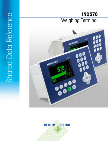
Introduction1.2.Model IdentificationThe model number and serial number are located on the data plate on the back of the terminal.Refer to Figure 1-1 to verify the IND9D57 that was ordered.Figure 1-1: IND9D57 Model Identification Numbers1-2METTLER TOLEDO IND9D57/Dyn-570 Dynamic Weighing System Installation Manual30416342 02 12/2018
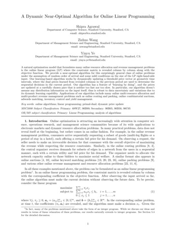
1.3.Internal ComponentsFigure 1-3 indicates the layout of the main components inside a typical IND9D57 enclosure.[Optionalblocks]0 volts ground reference24 VDC for I/OPhoto-Eye Inputs24VDC power supply forARM100, photo-eyes, orother 24V peripheralsAC distributionNeutralFuse for instrument powerFigure 1-2: IND9D57 Internal Layout1.4.Software FeaturesThe sections below summarize the main functional differences between the base model IND570and the Dyn-570 application.1.4.1.Dyn-570 Features1.4.1.1.Dedicated inputs for photo-eyes30416342 02 12/2018 Automated triggering of weighment Adjustable threshold settings to prevent unintentional triggering of photo eyes Ability to accurately weigh packages in motion, even if more than one package is on the scaleat one time. (Timing requirements still apply)METTLER TOLEDO IND9D57/Dyn-570 Dynamic Weighing System Installation Manual1-3
ble buffering and deferred transmission of weighment data, triggered by down-streamphoto-eyeAdditional filtering capabilities Tunable notch filter –eliminates natural resonances from conveyor equipment AutoTune feature – calculates weighing filtering parameters based on worst-case packagesample Dynamic Adjust feature – compensates for high-speed conveyor operation. Calculates offsetsbased on sample weighments of the longest and shortest package sizesEnhanced ID processing Two independent input sources to store barcode and dimensional data with the transactionrecord IDs can be added to the printed or stored transaction recordEnhanced Transaction Recording 100,000-record transaction table, including package data captured during weighment Easy export via FTP for off-line analysis and archivingCheckweighing 500 stored targets Adjustable reject output delay and duration timer for each target ID1.4.2.IND570 Features Unavailable or Changed in Dyn-5701.4.2.1.Scale Capacity & IncrementNote that multiple range and multi-interval operation are not supported in Dyn-570.1.4.2.2.Tare functions changedThe tare table, keyboard and pushbutton tare are not available while the Dyn application is running.However, a tare may be entered on the keypad, or a pushbutton tare performed, from the homescreen while the Dyn-570 application is not running. If a tare is set, Dyn-570 will use that tare forall transactions until the application is stopped and the tare cleared. When operating with a tare, theNet symbol “N” will be displayed above the weight unit on the terminal display.Auto-tare cannot be used in Dyn mode.1-4METTLER TOLEDO IND9D57/Dyn-570 Dynamic Weighing System Installation Manual30416342 02 12/2018
2.Installation2.1.Special Software Requirements2.1.1.Firmware VersionThe Dyn-570 application was created using TaskExpert . To run a TaskExpert application, theIND570 must have version 2.00.0036 firmware or higher installed.2.2.Installation NotesIf a complete IND570dyn terminal is ordered, all files required to run the Dyn application will beloaded during production and this chapter can be skipped. If the Dyn-570 application is ordered asa separate kit, the Dyn-570 application files must be loaded to the terminal before the applicationcan run.The required files are available for download at www.mt.com/IND570.2.2.1.Installation MethodThe following procedure outlines installation of the Dyn-570 application files.2.2.1.1.Loading via USB1. Make certain that the USB port has been enabled for both read and write functions in setup atCommunication Access/Security USB.2. Transfer the files downloaded from www.mt.com/IND570 to a USB flash drive in a TaskExpertfolder with the following path. The folders must be named exactly as shown:(USB drive) \ IND570 \ (SN of terminal) \ TaskExpert3. Insert the USB flash drive into the IND570 USB port.4. Enter setup and navigate to Maintenance Run Restore from USB.5. Select TaskExpert from the Restore selection box.6. Press the START softkeyto begin the loading process.7. When all files have been loaded, a message will be shown indicating a successful restore.8. Exit setup and remove the USB flash drive.9. The application is now ready for programming.30416342 02 12/2018METTLER TOLEDO IND9D57/Dyn-570 Dynamic Weighing System Installation Manual2-1
Installation2.2.1.2.Loading via FTP or Serial File TransferThe application files can also be loaded via FTP through the optional Ethernet port, or by serial filetransfer through the COM1 serial port. Refer to Appendix C, Communication, in the IND570 User'sGuide for details on transferring files to the IND570 via FTP or serial file transfer.2.3.Mounting the Packaged EnclosureThe IND9D57 is designed to mount on a flat surface, either vertically or horizontally. The hardwareto mount the terminal to its mounting surface is not included with the terminal and must besupplied locally. Ensure that the mounting hardware is capable of supporting the weight of theterminal which is approximately 40 lb (18 kg).Use the enclosure assembly as a template to mark the position of the mounting holes on themounting surface. Once the hole positions are established, drill holes in the mounting surface thatare suitable for the type of mounting hardware involved in the application. Then, using the locallysupplied mounting hardware, secure the enclosure to the mounting surface.2.4.Installing Cables and Connectors2.4.1.Provided Cable GlandsFigure 2-1 shows a typical arrangement of cable glands for a packaged IND570dyn, and theintended purpose of each.Home RunCablePhoto-EyeCableUSB orEthernet*AC PowerI/O CableFigure 2-1: IND570dyn Cable Glands* Note that the split grommet needed for the USB or Ethernet cable gland will be included with thedocumentation package shipped with the unit.2.4.2.Wiring Connections for Instrument PowerAll IND9D57 configurations come with provisions to provide power to the IND570 terminal and the24 VDC power supply. Wire terminals for the unit’s power power will always be labeled L, N andGND. 2-2L is for line, live or hotMETTLER TOLEDO IND9D57/Dyn-570 Dynamic Weighing System Installation Manual30416342 02 12/2018
N is for neutral GND is for the equipment grounding conductor or the protective earth (PE) connectionFor best system performance, instrument power must be connected to a clean, dedicated AC branchcircuit. Avoid running power lines in a conduit that also carries lines to “noisy” AC equipment suchas motors, welders and solenoids.L is fused with a 3.15 A, 250 VAC slow blow fuse. Once L has been fused, the label is changed to1A to denote that the circuit is protected.For best performance, do not add any other AC loads to the Instrument Power.2.4.3.Wiring Connections for Digital I/O Options2.4.3.1.24 VDC Inputs and OutputsThe unit is supplied with 4 wire terminals allowing for the attachment of the input photoeyes. Thesewire terminals are labeled 24V, 0V, I-1, and I-2. The 24V and 0V connections allow for providing24 VDC power to the photoeyes, and the I-1and I-2 connections are the input signal lines.For units that have the ExpressCheck or Dynamic Advanced software, a wire terminal is provided toconnect the output for a reject mechanism. This wire terminal will always be labeled REJ.2.4.3.2.Line Voltage OutputsAs with units using 24 VDC outputs, units using line voltage outputs that also have theExpressCheck or Dynamic Advanced software will be provided with a wire terminal labeled REJ forconnecting the output to control a reject mechanism.2.4.3.3.ARM100 ConnectionsWhen an optional ARM100 is ordered with the unit, the I/O points will connect directly at theARM100 terminals. Refer to the ARM100 Technical Manual for further details.2.5.Closing the EnclosureTo ensure that the IND9D57 provides continuous protection against the ingress of moisture anddust, be sure the following steps are taken:1. Ensure cord grips are appropriate for the outer diameter of the cable used. If there is too muchgap, replace the cord grip with an appropriate grip range.2. If a cord grip is not being used, be sure to install a plug to prevent debris from entering theenclosure.3. When adding cable entrances, avoid placing them in the top surface of the enclosure.Whenever possible, the bottom of the enclosure is the preferred location for cable entrances.Sides are the next best choice.4. Be sure that the quarter-turn latch is completely engaged when the enclosure door is closed.Watch for field-installed cabling getting caught in the door gasket. This can cause damage to30416342 02 12/2018METTLER TOLEDO IND9D57/Dyn-570 Dynamic Weighing System Installation Manual2-3
Installationthe wire and will also produce gaps in the seal that allow moisture and debris into theenclosure.2-4METTLER TOLEDO IND9D57/Dyn-570 Dynamic Weighing System Installation Manual30416342 02 12/2018
Manual de instalaciónIND9D57/Dyn-570Sistema de pesaje dinámico
IND9D57/Dyn-570Sistema
30416342 02 12/2018 METTLER TOLEDO IND9D57/Dyn-570 Dynamic Weighing System Installation Manual 1-3 1.3. Internal Components Figure 1-3 indicates the layout of the main components inside a typic

![API Ballot: [Ballot ID] – API 510 & API 570, Deferrals, Rev05](/img/5/api510andapi570deferralsrev5.jpg)